
Related Manuals for AXIOMTEK GMB850


Summary of Contents for AXIOMTEK GMB850
- Page 1 SDM500L GMB850 Mini-ITX gaming board ® Intel Smart Display Module (SDM-L) with Intel® Core™ Whiskey Lake U Processor...
-
Page 2: Disclaimers
Axiomtek does not make any commitment to update the information in this manual. Axiomtek reserves the right to change or revise this document and/or product at any time without notice. No part of this document may be reproduced, stored in a retrieval system, or transmitted, in any form or by any means, electronic, mechanical, photocopying, recording, or otherwise, without the prior written permission of Axiomtek Co., Ltd. - Page 3 ◼ When handling modules and components, wear an anti-static wrist strap, available from most electronic component stores. Trademarks Acknowledgments Axiomtek is a trademark of Axiomtek Co., Ltd. ® Windows is a trademark of Microsoft Corporation. AMI is a trademark of American Megatrend Inc.
-
Page 4: Table Of Contents
Table of Contents Disclaimers ..........................ii ESD Precautions ........................iii Chapter 1 Introduction ..........1 Features ........................1 Specifications ......................2 Utilities Supported ...................... 3 Chapter 2 Module and Pin Assignments ....4 Board IO ........................4 I/O Layout ........................5 Jumper Settings...................... -
Page 5: Chapter 1 Introduction
Chapter 1 Introduction The GMB850 is a new Mini-ITX gaming board which features the Intel® Core™ Alder Lake-S processor. It delivers high performance and supports a diverse range of multiple I/Os such as Gigabyte Ethernet port, USB 3.2 ports and Display port. Also, it comes with GLI verified optional TrustedBoot. -
Page 6: Specifications
GMB850 user’s manual Specifications ⚫ ⚫ LGA1700 socket supports 12th/13th Gen. Alder Lake-S/Raptor Lake-S Intel® Core™ i9/i7/i5/i3/Pentium® /Celeron® Processor Alder Lake-S processor @ 65W/35W TDP. ⚫ BIOS ⚫ American Megatrends Inc. BIOS. Optional TrustedBoot (Secure BIOS). ⚫ Socket type. Removeable BIOS chip ⚫... -
Page 7: Utilities Supported
GMB850 user’s manual Utilities Supported ⚫ Please download all the necessary driver from website or contact with sales for help. All specifications and images are subject to change without notice. Note Introduction... -
Page 8: Module And Pin Assignments
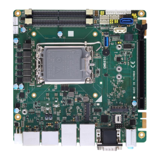
GMB850 user’s manual Chapter 2 Module and Pin Assignments Board IO Top View Module and Pin Assignments... -
Page 9: I/O Layout
GMB850 user’s manual I/O Layout Module and Pin Assignments... -
Page 10: Jumper Settings
The following illustrations show how to set up a jumper. Properly configure jumper settings on the GMB850 to meet your application purpose. Below you can find a summary table of jumpers and their default onboard settings. -
Page 11: Clear Cmos (Sw1)
GMB850 user’s manual 2.3.2 Clear CMOS (SW1) To restore BIOS optimal defaults, press the Clear CMOS button. Button Description Setting Clear CMOS button Clear CMOS 2.3.3 Golden finger and M.2 B key PCI-E Function select (JP2) Golden finger x1 and M.2 B key x2 configurable as below:... -
Page 12: Com3 & Com4: Function Select (Jps1)
GMB850 user’s manual 2.3.5 COM3 & COM4: Function select (JPS1) COM3 could be defined as RS232 or ccTalk COM4 could be defined as RS232 or ccTalk. Function Setting COM5 RS232 (Default) 1-3 close COM5 ccTalk 3-5 close COM6 RS232 (Default) -
Page 13: Connectors
GMB850 user’s manual Connectors Signals go to the other parts of the system through connectors. Loose or improper connection might cause problems. Please make sure all connectors are properly and firmly connected. Here is a table summarizing the connectors on the hardware. - Page 14 GMB850 user’s manual Description Item Label FAN connector FAN1,2 SODIMM DDR5 slot SODIM1,2 CN3,5 Internal USB2.0 CN13 C.C talk signal power select CCTK1,2 C.C talk header COM port3~5 SATAP1 SATA power Case open Front panel ATX/AT mode JSDOM1 SATA DOM power select...
-
Page 15: Com1 & Com2
GMB850 user’s manual 2.4.1 COM1 & COM2 COM1 : RS232/422/485 mode selected Connector: D-Sub 9 connector (TOP side) Signal Signal * RS-232/422/485 mode selected by BIOS COM2: Provide full RS232 Connector: D-Sub 9 connector (Button side) Signal Signal Module and Pin Assignments... -
Page 16: Com3/4/5
GMB850 user’s manual 2.4.2 COM3/4/5 CN4: COM3/COM4/COM5 Connector: 2x4 Box header, Pitch=2.0mm Signal Signal COM3_TX COM3_RX COM4_TX COM4_RX COM5_TX COM5_RX * The CN4 is header with COM3/COM4/COM5 serial ports. COM3 with Simple-232 / CCTalk1 select by JPS1(RS232 default) COM4 with Simple-232 / CCTalk2 select by JPS1(RS232 default) -
Page 17: Cctalk
GMB850 user’s manual 2.4.3 ccTalk CCTK1: ccTalk1 Connector: 1x4 Box header, Pitch=2.54mm Signal Signal +12V ccTalk/DATA * ccTalk1 signal is share with COM3 Please refer CN13 jumper for function setting. CCTK2: ccTalk2 Connector: 1x4 Box header, Pitch=2.54mm Signal Signal ccTalk/DATA * ccTalk2 signal is shared with COM4 Please refer to CN13 jumper for function setting. -
Page 18: Audio Output
GMB850 user’s manual 2.4.4 Audio output USPK1: Audio SPDIF output Connector: 1x4 header, Pitch=2.54mm Signal Signal SPDIF_OUT 2.4.5 Front Panel CN1: Front Panel Connector: 4x2 Pin header, Pitch=2.0mm Signal Signal Power_button- Power_LED_+ SATA_LED_N HDD_LED_+ Reset button 2.4.6 Digital I/O CN2: Digital I/O Connector: 2x5 Box header, Pitch=2.0mm... -
Page 19: Internal Usbhd Header
GMB850 user’s manual 2.4.7 Internal USBHD header USBHD1: USB 2.0 header Connector: 2x5 Box header, Pitch=2.0mm Signal Signal USB4_D- USB5_D- USB4_D+ USB5_D+ GND, ground GND, ground GND, ground GND, ground USBHD2: USB 2.0 header Connector: 2x5 Box header, Pitch=2.0mm Signal... -
Page 20: Sata Power
GMB850 user’s manual 2.4.8 SATA power SATAP1: 2-pin SATA power Connector: 1x2 header, Pitch=1.25mm Signal Signal GND, ground Note: Max input current 5V/0.5A SATAP2: 2-pin SATA power Connector: 1x2 header, Pitch=1.25mm Signal Signal GND, ground Note: Max input current 5V/0.5A... -
Page 21: Fan Connector
GMB850 user’s manual 2.4.9 Fan connector Fan1: 4-pin system Fan connector Connector: 1x4 wafer, Pitch=2.54mm Signal GND, ground FAN_OUT FAN_IN FAN_PWMO Fan2: 4-pin CPU Fan connector Connector: 1x4 wafer, Pitch=2.54mm Signal GND, ground FAN_OUT FAN_IN FAN_PWMO Module and Pin Assignments... -
Page 22: Power Input
GMB850 user’s manual 2.4.10 Power input VIN2: 4-pin DC power input Connector: 2x2, P4 4-pin ATX12V Signal Signal * With PCIe graphic card, the PCIe slot supports standard PCIe x16 graphic card @ 75W TDP. 2.4.11 Case open (Chassis Intrusion) CO1: 2-pin Case open (Chassis Intrusion) Connector: 1x2 box header, Pitch=2.00mm... -
Page 23: Ami Bios Setup Utility
GMB850 user’s manual Chapter 3 AMI BIOS Setup Utility The AMI UEFI BIOS provides users with a built-in setup program to modify basic system configuration. All configured parameters are stored in a flash chip to save the setup information whenever the power is turned off. This chapter provides users with detailed description about how to set up basic system configuration through the AMI BIOS setup utility. - Page 24 GMB850 user’s manual Hot Keys Description → Left/Right The Left and Right <Arrow> keys allow you to select a setup screen. The Up and Down <Arrow> keys allow you to select a setup screen or sub- Up/Down screen. The Plus and Minus <Arrow> keys allow you to change the field value of a +−...
-
Page 25: Appendix A Watchdog Timer
GMB850 user’s manual Appendix A Watchdog Timer A.1 About Watchdog Timer Software stability is a major issue in most application. Some embedded systems are not watched by human for 24 hours. It is usually too slow to wait for someone to reboot when computer hangs. - Page 26 GMB850 user’s manual Note: If N=00h, the time base is set to second. M = time value 00h: Time-out Disable 01h: Time-out occurs after 1 second 02h: Time-out occurs after 2 seconds 03h: Time-out occurs after 3 seconds FFh: Time-out occurs after 255 seconds If N=08h, the time base is set to minute.
Need help?
Do you have a question about the GMB850 and is the answer not in the manual?
Questions and answers