Table of Contents
Advertisement
Quick Links
Advertisement
Table of Contents

Subscribe to Our Youtube Channel
Related Manuals for AXIOMTEK GMB142 Series


Summary of Contents for AXIOMTEK GMB142 Series
- Page 1 GMB142 Series Gaming Mini-ITX Motherboard User’s Manual...
- Page 2 Axiomtek does not make any commitment to update the information in this manual. Axiomtek reserves the right to change or revise this document and/or product at any time without notice. No part of this document may be reproduced, stored in a retrieval system, or transmitted, in any form or by any means, electronic, mechanical, photocopying, recording, or otherwise, without the prior written permission of Axiomtek Co., Ltd.
-
Page 3: Safety Precautions
Safety Precautions Before getting started, please read the following important safety precautions. The GMB142 does not come equipped with an operating system. An operating system must be loaded first before installing any software into the computer. Be sure to ground yourself to prevent static charge when installing the internal components. -
Page 4: General Cleaning Tips
General Cleaning Tips You may need the following precautions before you begin to clean the computer. When you clean any single part or component for the computer, please read and understand the details below fully. When you need to clean the device, please rub it with a piece of dry cloth. Be cautious of the tiny removable components when you use a vacuum cleaner to absorb the dirt on the floor. - Page 5 Trademarks Acknowledgments Axiomtek is a trademark of Axiomtek Co., Ltd. ® Windows is a trademark of Microsoft Corporation. AMI is a trademark of American Megatrend Inc. IBM, PC/AT, PS/2, VGA are trademarks of International Business Machines Corporation. AMD is trademark of AMD Corporation, Inc.
-
Page 6: Table Of Contents
Table of Contents Safety Precautions ..................iii General Cleaning Tips .................. iv Section 1 Introduction ..........1 General Description ................1 System Specifications ................ 2 1.2.1 System ..................2 1.2.2 IO ....................3 1.2.3 Display ..................4 1.2.4 Software ................... 4 Utilities Supported ................ -
Page 7: Introduction
GMB142 User’s Manual Section 1 Introduction This chapter contains general information and detailed specifications of the GMB142. The Chapter 1 includes the following sections: ⚫ General Description ⚫ System Specification ⚫ Dimensions ⚫ I/O Outlets ⚫ Packing List ⚫ Model List General Description ⚫... -
Page 8: 1.2 System Specifications
(R2544/ R2514/ R2314 series support PCIe X8 signal and R2312 supports PCIe X4 signal) 1 x Full-size Mini-PCIe socket. Support PCI-Express X1 and USB signal ◼ Two Gold finger interface to support Axiomtek gaming I/O module ◼ AMD R2000 series SoC had function/signal limitation for onboard PCIe X16 slot. NOTE: Please re-check with sales if you intend to plug PCIe card on GMB142. - Page 9 Storage Temperature ⚫ -40°C ~ +85°C ◼ Security ⚫ Onboard TCG 2.0 compliant TPM ◼ Axiomtek TrustedBoot (Security boot) for optional. ◼ 1.2.2 ⚫ 1 x internal vertical connector ◼ External: 2 x USB3.0 , 2 x USB 2.0 ◼...
-
Page 10: Display
GMB142 User’s Manual Others ⚫ 1 x 4-pin CPU Fan connector ◼ 1 x 3-pin system Fan connector ◼ 1 x 8-pin front panel ◼ 1.2.3 Display Graphic ⚫ AMD Ryzen™ Embedded R2000 Series APU build-In Vega GPU with up to 8CUs ◼... -
Page 11: Function Block
GMB142 with CPU Fan x 1 ⚫ DDR4 SO-DIMM memory (optional) ⚫ SATAIII or CFast card Storage (optional) ⚫ Cable kits (optional) ⚫ If you cannot find this package or any items are missing, please contact Axiomtek distributors immediately. Introduction... - Page 12 GMB142 User’s Manual This page is intentionally left blank. Introduction...
-
Page 13: Board Layout And Pin-Outs
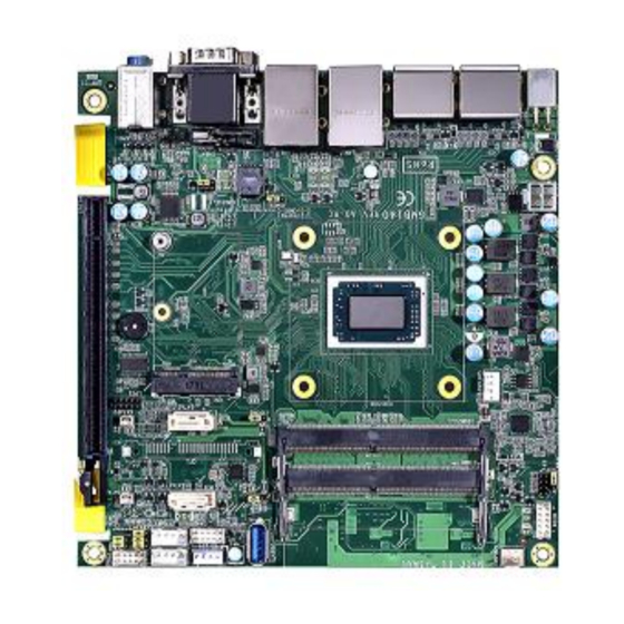
GMB142 User’s Manual Section 2 Board Layout and Pin-outs Board Dimensions The following diagrams show you dimensions and outlines of the GMB142. Board Layout and Pin-outs... -
Page 14: I/O Outlets
GMB142 User’s Manual I/O Outlets The following figures show you I/O outlets on front view of the GMB142 R2544/ R2514/ R2314 Model: LAN1 LAN2 COM1 Audio USB3.0 USB2.0 COM2 R2312 Model: LAN1 LAN2 COM1 Audio USB3.0 USB2.0 COM2 Board Layout and Pin-outs... - Page 15 GMB142 User’s Manual Top View I/O View R2544/ R2514/ R2314 Model: R2312 Model: Board Layout and Pin-outs...
-
Page 16: Jumper / Switch Settings
GMB142 User’s Manual Jumper / Switch Settings The jumper is a small component consisting of a jumper clip and jumper pins. Install jumper clip on 2 jumper pins to close, and remove jumper clip from 2 jumper pins to open. The following illustration shows how to set up the jumper. -
Page 17: Connectors
GMB142 User’s Manual Connectors Description interface Item Label Full RS232/422/485 D-Sub 9-pin COM1 Full RS232 D-Sub 9-pin COM2 COM3 ~ COM6 Simple COM or 5V TTL 2x10-pin box header CCTK1 ccTalk compatible with COM4 1x4-pin box header CCTK2 ccTalk compatible with COM5 1x4-pin box header VIN1/VIN3 DC 12V power input... -
Page 18: Serial Port Connector (Com1, Com2)
GMB142 User’s Manual 2.3.1 Serial Port Connector (COM1, COM2) COM1: RS232/422/485 mode selected Connector: D-Sub 9 connector (TOP one) Signal Signal * RS-232/422485 mode selected by BIOS COM2: Provide full RS232 Connector: D-Sub 9 connector (Button one) Signal Signal NA/5V/12V * Pin-9 defines selected by jumper. -
Page 19: Com3, Com4, Com5, Com6
GMB142 User’s Manual 2.3.2 COM3, COM4, COM5, COM6 COM3, COM4, COM5, COM6 provides simple RS-232. COM3 support Simple COM or TTL-5V COM4 support Simple COM or CCTalk1. COM5 support Simple COM or CCTalk2. COM6 support Simple COM and share signal with PCIe golden finger or TTL3V *For mode selected, please refer to Jumper Setting. -
Page 20: Cctalk Connector ( Cctk1, Cctk2 )
GMB142 User’s Manual 2.3.3 ccTalk connector ( CCTK1, CCTK2 ) ccTalk1: Connector: 1x4 wafer, Pitch: 2.5mm Signal Signal +12V Data Mating connector: JST XHP-4 ccTalk2: Connector: 1x4 wafer, Pitch: 2.5mm Signal Signal +12V Data Mating connector: JST XHP-4 Board Layout and Pin-outs... -
Page 21: Power Connector
GMB142 User’s Manual 2.3.4 Power connector VINI1 and VIN2: DC 12V input Connector: 2x2, p4 4-pin 12V connector Signal Signal +12V +12V * Without PCIe graphic card, you can choose either internal (VIN1) or external (VIN2) 4-pin power connector for power input. -
Page 22: Internal Audio Pin Header
GMB142 User’s Manual 2.3.6 Internal Audio pin header SPK1: 6W + 6W, 2-ch audio output Box header: 1x4 Pin, Pitch=2.54mm Signal Signal SPK2: S/PDIF Box header: 1x4 Pin, Pitch=2.54mm Signal Signal S/PDIF_out Board Layout and Pin-outs... -
Page 23: Dio1: 8-Bit Gpio
GMB142 User’s Manual 2.3.7 DIO1: 8-bit GPIO Box header: 2x5 Pin, Pitch=2.00mm Signal Signal Mating connector: Board Layout and Pin-outs... -
Page 24: Fp1: Front Panel Header
GMB142 User’s Manual 2.3.8 FP1: Front Panel Header Connector: 2x4 wafer, Pitch: 2.0mm Signal Signal Power button Power_LED+ HDD_LED- HDD_LED+ Reset 2.3.9 SATAP3: SATA power Connector:1x4 wafer, Pitch: 2.54mm Signal Signal +12V Note: Max support current 12V/1A , 5V/2A Board Layout and Pin-outs... -
Page 25: Satap1 & P2: Sata Power
GMB142 User’s Manual 2.3.10 SATAP1 & P2: SATA power Connector:1x2 wafer, Pitch: 1.25mm Signal Signal Note: Max support current 5V/1A Jumper Definition Jumper Setting 1-2 : SATA1/2 Built-in +5V JSDOM1/2 SATA1/2 PIN7 define 2-3 : Normal (Default) If set JSDOM1 / JSDOM2 pin 1-2 close, onboard blue LED will light on. NOTE: Board Layout and Pin-outs... - Page 26 GMB142 User’s Manual This page is intentionally left blank. Board Layout and Pin-outs...
-
Page 27: Ami Bios Setup Utility
GMB142 User’s Manual Section 4 AMI BIOS Setup Utility The AMI UEFI BIOS provides users with a built-in setup program to modify basic system configuration. All configured parameters are stored in a flash chip to save the setup information whenever the power is turned off. This chapter provides users with detailed description about how to set up basic system configuration through the AMI BIOS setup utility. -
Page 28: Navigation Keys
GMB142 User’s Manual Navigation Keys The BIOS setup/utility uses a key-based navigation system called hot keys. Most of the BIOS setup utility hot keys can be used at any time during the setup navigation process. These keys include <F1>, <F2>, <Enter>, <ESC>, <Arrow> keys, and so on. NOTE: Some of the navigation keys differ from one screen to another.
Need help?
Do you have a question about the GMB142 Series and is the answer not in the manual?
Questions and answers