Table of Contents

Subscribe to Our Youtube Channel
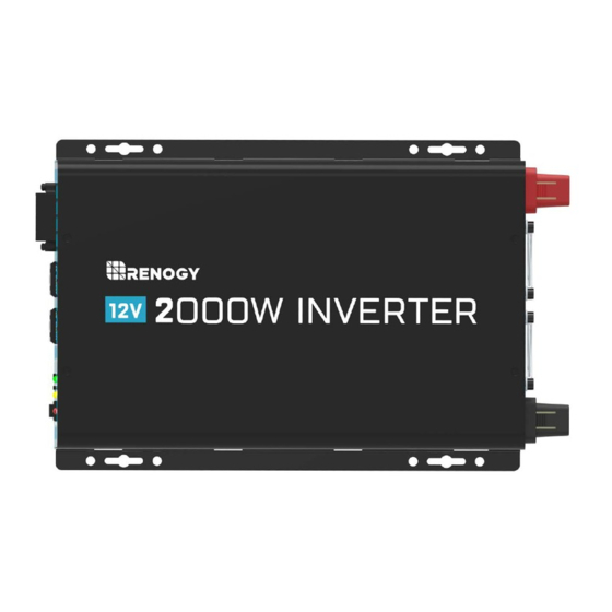
Related Manuals for Renogy R-INVT-PGH1-20111S-G1


Summary of Contents for Renogy R-INVT-PGH1-20111S-G1
- Page 1 BATTERY POWER INVERTERS 12V Pure Sine Wave Inverter Manual 2000w Version 1.2...
- Page 2 Important Safety Instructions Please save these instructions. This manual contains important safety, installation, and operating instructions for the inverter. The following symbols are used throughout the manual: Indicates a potentially dangerous condition. Use extreme caution WARNING when performing this task. Indicates a critical procedure for safe and proper operation of the CAUTION inverter.
- Page 3 NEVER connect the AC output of the unit directly to an Electrical Breaker Panel/ Load Centre which is also fed from the utility power / generator. When connecting battery terminals, ensure the polarity of the battery connections is correct. Incorrect polarity may cause permanent damage to the unit. Be careful when touching bare terminals of capacitors as they may retain high lethal voltages even after power is removed.
-
Page 4: Table Of Contents
Table of Contents General Information Included Components Identification of Parts (AC Side) Identification of Parts (DC Side) Installation Location Recommendations Sizing a Battery Bank Grounding DC Side Connection Operation AC Side Operation Eco Power Saving Mode Instruction Inverter Troubleshooting Specifications Dimensions... -
Page 5: General Information
Power Saving Mode to conserve energy Pure Sine Wave The Renogy Power Inverters output a pure sine wave similar to the waveform of the grid power. In a pure sine wave, the voltage rises and falls in a smooth fashion with very low harmonic distortion and cleaner utility-like power. -
Page 6: Included Components
Included Components The Renogy Pure Sine Wave Battery Inverters will be shipped with inverter cables and a remote control for powering the inverter on or off. Inverter Model Gauge 2000W 4AWG*2 2FT Wired remote control List dimensions 2.88 x 2.31 x .94in / 73 x 58.7 x 23mm Thickness 0.63in / 1.5mm... -
Page 7: Identification Of Parts (Ac Side)
Identification of Parts (AC Side) Figure 2: 2000W Inverter Key Parts 1. High Output AC Terminals — These terminals are for connecting 110 Volt A C devices that require more than 15 amps to operate or for connection to distributed wiring that has multiple AC outlets. -
Page 8: Identification Of Parts (Dc Side)
Fault LED (Red) — The red indicator turns on as the inverter shuts down due to overheating, overload, under voltage, or over voltage. Immediately turn off all AC appliances if the Fault LED is lit. Allow the inverter to cool before restart. -
Page 9: Installation
Installation Make sure inverter is in the off position before connecting anything. WARNING Do not over-torque or over tighten the terminals. This could potentially CAUTION damage the unit. Refer to the technical specifications for max wire sizes on the controller CAUTION and for the maximum amperage going through wires. -
Page 10: Sizing A Battery Bank
Utilize the formula Watts = Volts * Amps Determine Amps used for how many hours – Amp-hour (Ah) For this Renogy inverter, the battery bank will be 12 volts direct current (12 VDC) Example A Microwave oven... -
Page 11: Grounding
Grounding The Renogy Pure Sine Wave inverters come equipped with a grounding lug to appropriately ground to earth or to another designated ground (for example, a metal frame of an RV). The connections to ground must be tight and against bare metal. Whether using the inverter in a mobile application, such as an RV, or in a building, grounding is highly recommended. - Page 12 1.Flip inverter power to OFF position (on 2.Remove Cap, then unscrew inverter AC side) terminals and connect battery connections. Then tighten. ① ② ③ ④ ⑤ ⑥...
-
Page 13: Operation
Operation Assuming proper battery connection, the inverter is now ready for use. AC Side Operation 1.Connect electronic devices to electrical socket (s) on inverter. Flip inverter power to ON position (on AC side) 2. When finished, switch AC devices off FIRST, then turn off inverter switch Avoid switching on the inverter with the load (electronic devices) already CAUTION... -
Page 14: Specifications
Specifications Model R-INVT-PGH1-20111S-G1 Continuous Power 2000 W Input Voltage 12V DC Output Voltage 110V AC +/-10% Peak surge 4000 W Efficiency > 90% Frequency 50Hz/60Hz No load current draw < 2.0A Low voltage alarm 10.5V ± 0.5V DC Low voltage 10.0V ±... -
Page 15: Dimensions
This equipment has been tested and found to comply with the limits for a class B digital device, pursuant to part 15 of the FCC Rules. These limits are designed to provide reasonable protection against harmful interference in a residential installation. This equipment generates, uses and can radiate radio frequency energy and if not installed and used in accordance with the instructions, may cause harmful interference to radio communications. - Page 16 RENOGY.COM Renogy reserves the right to change the contents of this manual without notice. 2775 E Philadelphia St, Ontario, CA 91761, USA 909-287-7111 www.renogy.com customerservice@renogy.com 苏州高新区科技城培源路1号5号楼-4 400-6636-695 https://www.renogy.cn sales@renogy.cn https://www.renogy.jp onlinestorejp@renogy.com https://ca.renogy.com onlinestoreca@renogy.com https://au.renogy.com onlinestoreau@renogy.com https://uk.renogy.com onlinestoreuk@renogy.com https://de.renogy.com onlinestorede@renogy.com https://fr.renogy.com...
Need help?
Do you have a question about the R-INVT-PGH1-20111S-G1 and is the answer not in the manual?
Questions and answers