Key Automation 14A Instructions And Warnings For Installation And Use
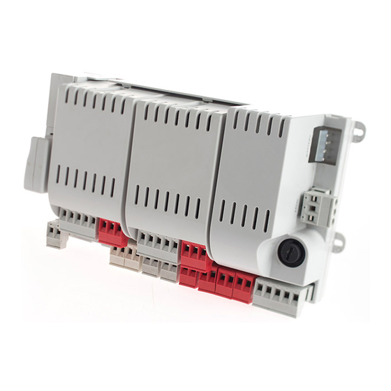
Modular control unit for one or two 24 vdc motors
Hide thumbs
Also See for 14A:
- Instructions and warnings for installation and use (116 pages) ,
- Instructions and warnings for installation and use (132 pages)
Table of Contents
Advertisement
Quick Links
Istruzioni ed avvertenze per l'installazione e l'uso
Instructions and warnings for installation and use
Instructions et avertissements pour l'installation et l'usage
Anleitungen und Hinweise zu Installation und Einsatz
Instrucciones y advertencias para su instalación y uso
Instruções e advertências para a instalação e utilização
Instrukcje i zalecenia dotyczące instalacji i użytkowania
Logique de commande modulaire pour un ou deux moteurs 24 Vcc
Modulares Steuergerät für einen oder zwei 24-VDC-Motoren
Centrala modułowa dla jednego lub dwóch silników 24 VDC
Centrale modulare per uno o due motori 24 Vdc
Modular control unit for one or two 24 Vdc motors
Central modular para uno o dos motores de 24 Vcc
Unidade modular para um ou dois motores 24 Vdc
14A
Advertisement
Table of Contents

Related Manuals for Key Automation 14A


Summary of Contents for Key Automation 14A
- Page 1 Istruzioni ed avvertenze per l’installazione e l’uso Instructions and warnings for installation and use Instructions et avertissements pour l’installation et l’usage Anleitungen und Hinweise zu Installation und Einsatz Instrucciones y advertencias para su instalación y uso Instruções e advertências para a instalação e utilização Instrukcje i zalecenia dotyczące instalacji i użytkowania Centrale modulare per uno o due motori 24 Vdc Modular control unit for one or two 24 Vdc motors...
-
Page 2: Table Of Contents
Operating the automation using the display programmer page 26 Operating the automation using the receiver page 26 Diagnostic page 27 Customising the system - Basic settings 14A page 27 Night lights page 29 Testing and commissioning page 29 Testing page 29... - Page 3 If in any doubt regarding installation, do not proceed and con- ses by a person with similar qualifications, to prevent tact the Key Automation Technical Service for clarifications. all risks; Under European legislation, an automatic door or...
- Page 4 Key Automation reserves the right to amend these instructions if necessary; they and/ children must be supervised to ensure that they do not or any more recent versions are available at play with the equipment;...
-
Page 5: Description Of The Control Unit
2 - INTRODUCING THE PRODUCT 2.1 - Description of the control unit The 14A control unit is a modular system for the control of Key programming and constant monitoring of the control unit’s status; the Automation motors for the electric opening and closure of swing and menu structure also allows easy setting of working times and sliding gates, barriers and garage doors. -
Page 6: List Of Cables Required
TECHNICAL CHARACTERISTICS 14AF 14AB 14AB2 * 14AB2F ** Power supply (L-N) 24Vac (+10%-15%) 50/60 Hz 230Vac (+10%-15%) 50/60 Hz Rated power maximum 210W maximum 300W maximum 300W Photocell power supply output 24Vdc (without regulation) max 250mA Flashing light output 24Vdc (without regulation) 25W Courtesy light output 24Vdc (without regulation) 15W Electric lock output... -
Page 7: Installing The Product
4 - INSTALLING THE PRODUCT 4.1 - Electrical connections WARNING - Before making the connections, ensure that the control unit is not powered up POWER SUPPLY CONNECTIONS Power supply 230 Vac 50-60 Hz Earth Power supply neutral 230 Vac 50-60 Hz ECLIPSE NEG POS NEG POS... -
Page 8: Electric Connections
ELECTRICAL CONNECTIONS PO24 POWER MODULE FOR ENERGY SAVING (M1 - M2) 12/24 12/24 COM OUT AC/DC AC/DC 12/24 COM OUT 12/24 AC/DC AC/DC N.B.: Only for sliding gates PO24 CONNECTIONS Limit switch 1 input (only for SUN) Limit switch 2 input (only for SUN) Limit switch / encoder power supply positive common (12 Vdc 50 mA MAX) Encoder S signal input Encoder power supply negative... -
Page 9: Using The Display Programmer
In normal mode, i.e. when the system is powered up normally SCORRI GIÚ and the display programmer is connected, press X until the name KEY AUTOMATION appears. This will display the following status messages: Il diagramma di flusso completo del programmatore display si trova al punto 6.3 a pag. -
Page 10: Operating The Automation Using The Display Programmer
It is important to allow for the gate’s moment of inertia and to check that the decelerations set allow the motors to brake the leaves of the gate before they reach the limit position. N.B. COMPLETE PROGRAMMING is no longer possible in the 14A FAST control unit 4.4 - Operating the automation using the display programmer... -
Page 11: Diagnostic
4.6 - Diagnostic A number of parameters, including the current absorption or motor speed, can be viewed at any time using this function. Proceed as follows: MOTOR 1 CURRENT (mA) MOTOR 2 CURRENT (mA) MOTOR 1 POSITION (%) MOTOR 2 POSITION (%) DIAGNOSTIC MOTOR 1 SPEED (%) MOTOR 2 SPEED (%) - Page 12 PARAMETERS DESCRIPTION DEFAULT MIN. MAX. UNIT Motor speed during closing deceleration phase. 1 = minimum SLOW DOWN 2 = low CLOSING SPEED 3 = medium 4 = high 5 = maximum Motor speed during closing deceleration phase. SLOW DOWN 1 = minimum CLOSING SPEED 2 = low FASTLINE...
-
Page 13: Night Lights
4.8 - Night lights The night lights function automatically with the Eclipse flashing light NIGHT LIGHTS connected appropriately. To customise, proceed as follows: PARAMETERS DESCRIPTION DEFAULT MIN. MAX. UNIT 0 = Night Light System deactivated 1 = Night Light System active (automatically AUTOMATIC LIGHT activated during learning of the stroke with the ECLIPSE flashing light connected) -
Page 14: Customising The System - Advanced Settings 14A
6 - FURTHER DETAILS 6.1 - Customising the system - Advanced settings If necessary, users may select the ADVANCED SETTINGS, which CAUTION: the parameters may vary with respect to those in the table allow modification of the control unit’s advanced parameters. below, depending on the motor to be installed. - Page 15 Restoring the default values *** The OPEN command from the transmitter and the 14A control unit will activate the parcial gate electric lock when the parameter is set on 3 or 4. The activation time is as set in parameter 18 **** If the setting is 4, the GATE OPEN WARNING LIGHT output must be connected to the coil of a relay (24 Vdc coil).
- Page 16 6.2 - RX4Y receiver If necessary, users may select the RX4X RECEIVER MENU, used to RX4Y manage the parameters relating to the radio unit. Proceed as follows ▲▼ ADD TX Allows a new code to be memorised in the receiver DELETE TX Allows deletion of a code from the receiver DELETE ALL...
-
Page 17: Programmer Flow Chart
6.3 - Programmer flow chart QUICK PROGRAMMING ▲ ▼ FULL MOTOR 1 CURRENT (mA) PROGRAMMING MOTOR 2 CURRENT (mA) MOTOR 1 POSITION (%) ▲ ▼ MOTOR 2 POSITION (%) DIAGNOSTIC MOTOR 1 SPEED (%) MOTOR 2 SPEED (%) ▲ ▼ TOTAL CYCLES (CYCLES) CYCLES LEFT BEFORE SERVICE SOFTWARE VERSION... - Page 18 7 - DECLARATION OF CONFORMITY DICHIARAZIONE DI INCORPORAZIONE DI QUASI-MACCHINA DECLARATION OF INCORPORATION OF PARTLY COMPLETED MACHINERY Il so�oscri�o Nicola Michelin, Amministratore Delegato dell’azienda The undersigned Nicola Michelin, General Manager of the company Key Automa�on srl, Via Meucci, 23 - 30027 San Donà di Piave (VE) – ITALIA dichiara che il prodo�o �po: declares that the product type: Centrale di comando modulare a 24 Vdc...
- Page 20 Key Automation S.r.l. Via Meucci 23 - 30027 San Donà di Piave (VE) T. +39 0421 307456 - info@keyautomation.it Instruction version www.keyautomation.com 580IS14A REV.15...
Need help?
Do you have a question about the 14A and is the answer not in the manual?
Questions and answers