Key Automation 14A Instructions And Warnings For Installation And Use
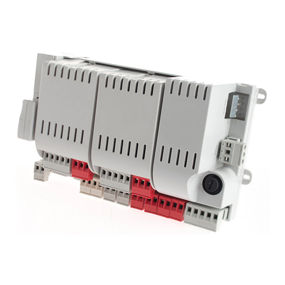
Modular control unit for one or two 24 vdc motors
Hide thumbs
Also See for 14A:
Table of Contents
Advertisement
Available languages
Available languages
Quick Links
Istruzioni ed avvertenze per l'installazione e l'uso
Instructions and warnings for installation and use
Instructions et avertissements pour l'installation et l'usage
Instrucciones y advertencias para su instalación y uso
Anleitungen und Hinweise zu Installation und Einsatz
Instruções e advertências para a instalação e utilização
Centrale modulare per uno o due motori 24 Vdc
Modular control unit for one or two 24 Vdc motors
Logique de commande modulaire pour un ou deux moteurs 24 Vcc
Central modular para uno o dos motores de 24 Vcc
Modulares Steuergerät für einen oder zwei 24-VDC-Motoren
Unidade modular para um ou dois motores 24 Vdc
Centrala modułowa dla jednego lub dwóch silników 24 VDC
Management
System
ISO 9001:2008
www.tuv.com
ID 9105043769
14A
Advertisement
Chapters
Table of Contents

Related Manuals for Key Automation 14A


Summary of Contents for Key Automation 14A
- Page 1 Istruzioni ed avvertenze per l’installazione e l’uso Instructions and warnings for installation and use Instructions et avertissements pour l’installation et l’usage Instrucciones y advertencias para su instalación y uso Anleitungen und Hinweise zu Installation und Einsatz Instruções e advertências para a instalação e utilização Centrale modulare per uno o due motori 24 Vdc Modular control unit for one or two 24 Vdc motors Logique de commande modulaire pour un ou deux moteurs 24 Vcc...
-
Page 2: Table Of Contents
INDICE Avvertenze per la sicurezza pag. 3 Introduzione al prodotto pag. 4 Descrizione della centrale pag. 4 Descrizione dei collegamenti pag. 4 Modelli e caratteristiche tecniche pag. 4 Elenco cavi necessari pag. 5 Verifiche preliminari pag. 5 Installazione del prodotto pag. - Page 3 ATTENZIONE - I dati e le informazioni indicate in questo ma- presenti; nuale sono da ritenersi suscettibili di modifica in qualsiasi mo- mento e senza obbligo di preavviso da parte di Key Automation se il cavo di alimentazione risulta danneggiato esso deve essere S.r.l.
-
Page 4: Introduzione Al Prodotto
2 - INTRODUZIONE AL PRODOTTO 2.1 - Descrizione della centrale La centrale 14A è un sistema di controllo modulare per i motori Key dello stato della centrale; inoltre la struttura a menu permette una semplice impostazione dei tempi di lavoro e delle logiche di funzio- Automation per l’apertura e la chiusura elettrica di cancelli a battente,... -
Page 5: Elenco Cavi Necessari
CARATTERISTICHE TECNICHE 14AB 14AB2 * Alimentazione (L-N) 230Vac (+10% - 15%) 50/60 Hz 230Vac (+10% - 15%) 50/60 Hz Potenza nominale 210W massimo 300W massimo Uscita alimentazione fotocellule 24Vdc (non regolato) massimo 250mA 24Vdc (non regolato) massimo 250mA Uscita lampeggiante 24Vdc (non regolato) 25W 24Vdc (non regolato) 25W Uscita luce di cortesia... -
Page 6: Installazione Del Prodotto
4 - INSTALLAZIONE DEL PRODOTTO 4.1 - Collegamenti elettrici ATTENZIONE - Prima di effettuare i collegamenti verificare che la centrale non sia alimentata COLLEGAMENTI PO24 MODULO DI POTENZA PO24 Ingresso finecorsa 1 Ingresso finecorsa 2 Comune finecorsa / positivo alimentazione encoder (12 Vdc 50 mA MAX) Ingresso segnale encoder S Negativo alimentazione encoder... -
Page 7: Utilizzo Del Programmatore Display
SCORRI GIÚ al sistema e il programmatore display è collegato premere X fino a quando compare la dicitura KEY AUTOMATION. In questo modo si Il diagramma di flusso completo del programmatore display si trova potranno vedere i seguenti messaggi di stato: al punto 6.3 a pag. -
Page 8: Autoapprendimento Della Corsa
4.3 - Autoapprendimento della corsa parametri fondamentali quali la lunghezza della corsa e dei rallen- La prima volta che la centrale viene alimentata dev’essere eseguita tamenti. una procedura di auto apprendimento che permetta di rilevare dei PROGRAMMAZIONE VELOCE Con questa programmazione i rallentamenti saranno reimpostati con la medesima percentuale sia in apertura che in chiusura. Seguire il seguente diagramma con il display programmatore. -
Page 9: Diagnostica
4.6 - Diagnostica In qualsiasi momento è possibile visualizzare alcuni parametri quali l’assorbimento di corrente o la velocità dei motori tramite questa funzione. Procedere come segue: CORRENTE MOTORE 1 (mA) CORRENTE MOTORE 2 (mA) POSIZIONE MOTORE 1 (%) POSIZIONE MOTORE 2 (%) DIAGNOSTICA VELOCITÁ... -
Page 10: Luci Notturne
Velocità del motore in chiusura durante la fase di rallentamento. 1 = minima VELOCITÁ RALLENTAMENTO 2 = bassa CHIUSURA 3 = media 4 = alta 5 = massima Configurazione SS: 0 = Normale (AP-ST-CH-ST-AP-ST…) 1 = Alternato STOP (AP-ST-CH-AP-ST-CH…) PASSO PASSO 2 = Alternato (AP-CH-AP-CH…) 3 = Condominiale –... -
Page 11: Collaudo E Messa In Servizio
5 - COLLAUDO E MESSA IN SERVIZIO DELL’AUTOMAZIONE Il collaudo dell impianto va eseguito da un tecnico qualificato che dalle normative, in particolare la norma EN12445 che indica i meto- deve effettuare le prove richieste dalla normativa di riferimento in di di prova per gli automatismi per porte e cancelli. -
Page 12: Approfondimenti
6 - APPROFONDIMENTI 6.1 - Personalizzazione dell’impianto - SETTAGGI AVANZATI In caso di necessità è possibile selezionare i SETTAGGI AVANZATI Procedere come segue: che permettono di modificare i parametri avanzati dell’unità di SETTAGGI controllo. AVANZATI PARAMETRI DESCRIZIONE DEFAULT MIN. MAX. UNITÁ Comportamento PHOTO1 in partenza da chiuso 0 = PHOTO 1 disattivata FOTO 1... - Page 13 0 = disabilitato UOMO PRESENTE 1 = abilitato (le sicurezze vengono disabilitate) 0 = disattivata SPIA CANCELLO 1 = spia cancello aperto ON/OFF APERTO 2 = spia cancello aperto proporzionale Soglia cicli richiesta assistenza. A cancello chiuso il lampeggiante x 1000 eseguirà...
-
Page 14: Ricevente Rx4X
6.2 - RICEVENTE RX4X In caso di necessità è possibile selezionare il MENU RICEVEN- Procedere come segue: TE RX4X che permette di gestire i parametri relativi alla radio. RX4X AGGIUNGI TX Permette di memorizzare un nuovo codice nella ricevente CANCELLA TX Permette di cancellare un codice presente nel ricevitore CANCELLA TUTTO Cancella tutta la memoria del ricevitore... -
Page 15: Diagramma Di Flusso Del Programmatore
6.3 - Diagramma di flusso del programmatore PROGRAMMAZIONE VELOCE ▲ ▼ CORRENTE MOTORE 1 (mA) PROGRAMMAZIONE CORRENTE MOTORE 2 (mA) COMPLETA POSIZIONE MOTORE 1 (%) ▲ ▼ POSIZIONE MOTORE 2 (%) DIAGNOSTICA VELOCITÁ MOTORE 1 (%) VELOCITÁ MOTORE 2 (%) ▲... -
Page 16: Istruzioni Ed Avvertenze Destinate All'utilizzatore Finale
Key Automation non è però il produttore della vostra nare più a lungo possibile ed in completa sicurezza. Concordate automazione, che è invece il risultato di un’opera di analisi, valu- con il vostro installatore un piano di manutenzione con frequenza tazione, scelta dei materiali, e realizzazione dell’impianto eseguita... - Page 17 NOTE...
- Page 18 TABLE OF CONTENTS Safety warnings page 19 Product Introduction page 20 Description of the control unit page 20 Description of the connections page 20 Models and technical characteristics page 20 List of cables required page 21 Preliminary Checks page 21 Installing the Product page 22 Electric connections...
-
Page 19: Safety Warnings
Read the instructions carefully before proceeding with installation. should this occur, disconnect the power supply immediately and contact a Key Automation Service Centre. Use of the automation The design and manufacture of the devices making up the system in these conditions may cause hazards;... -
Page 20: Product Introduction
2 - INTRODUCING THE PRODUCT 2.1 - Description of the control unit The 14A control unit is a modular system for the control of Key the menu structure also allows easy setting of working times and Automation motors for the electric opening and closure of swing and operating modes. -
Page 21: List Of Cables Required
TECHNICAL CHARACTERISTICS Power supply (L-N) 230Vac (+10% - 15%) 50/60 Hz 230Vac (+10% - 15%) 50/60 Hz Rated power maximum 210W maximum 300W Photocell power supply output 24Vdc (without regulation) maximum 250mA 24Vdc (without regulation) maximum 250mA Flashing light output 24Vdc (without regulation) 25W 24Vdc (without regulation) 25W Courtesy light output... -
Page 22: Installing The Product
4 - INSTALLING THE PRODUCT 4.1 - Electrical connections WARNING - Before making the connections, ensure that the control unit is not powered up PO24 CONNECTIONS PO24 POWER MODULE Limit switch 1 input Limit switch 2 input Limit switch / encoder power supply positive common (12 Vdc 50 mA MAX) Encoder S signal input Encoder power supply negative... -
Page 23: Using The Display Programmer
SCROLL DOWN and the display programmer is connected, press X until the name The complete flow chart for the display programmer is in point 6.3 KEY AUTOMATION appears. This will display the following status messages: on page 31. KEY TO MAIN CONTROL... -
Page 24: Auto-Learning Of The Travel Stroke
4.3 - Auto-learning of the travel stroke The first time the control unit is powered up, an auto-learning such as the travel stroke length and deceleration points. procedure must be carried out to acquire fundamental parameters QUICK PROGRAMMING If this programming mode is used, the decelerations will reset to the default values with the same percentage during both opening and closing. -
Page 25: Diagnostic
4.6 - Diagnostic A number of parameters, including the current absorption or motor speed, can be viewed at any time using this function. Proceed as follows: MOTOR 1 CURRENT (mA) MOTOR 2 CURRENT (mA) MOTOR 1 POSITION (%) MOTOR 2 POSITION (%) DIAGNOSTIC MOTOR 1 SPEED (%) MOTOR 2 SPEED (%) -
Page 26: Night Lights
Motor speed during closing deceleration phase. 1 = minimum 2 = low SLOW DOWN 3 = medium CLOSING SPEED 4 = high 5 = maximum SS configuration: 0 = Normal (OP-ST-CL-ST-OP-ST…) 1 = Alternate STOP (OP-ST-CL-OP-ST-CL…) STEP BY STEP 2 = Alternate (OP-CL-OP-CL…) 3 = Apartment block –... -
Page 27: Testing And Commissioning
5 - TESTING AND COMMISSIONING THE AUTOMATION SYSTEM The system must be tested by a qualified technician, who must the relevant regulatory requirements, especially the EN12445 perform the tests required by the relevant standards in relation standard which specifies the test methods for gate and door to the risks present, to check that the installation complies with automation systems. -
Page 28: Details
6 - FURTHER DETAILS 6.1 - Customising the system - ADVANCED SETTINGS If necessary, users may select the ADVANCED SETTINGS, which Proceed as follows: allow modification of the control unit’s advanced parameters. ADVANCED SETTINGS PARAMETERS DESCRIPTION DEFAULT MIN. MAX. UNIT Use of PHOTO1 when starting from closed 0 = PHOTO 1 deactivated PHOTO 1... - Page 29 0 = off DEAD MAN 1 = on (safety devices disabled) 0 = deactivated GATE OPEN 1 = gate open light ON/OFF INDICATOR 2 = gate open light proportional Service interval cycle threshold. When the gate is closed, the x 1000 MAINTENANCE flashing light flashes quickly without stopping.
-
Page 30: Rx4X Receiver
6.2 - RX4X RECEIVER If necessary, users may select the RX4X RECEIVER MENU, used Proceed as follows: to manage the parameters relating to the radio unit. RX4X Allows a new code to be memorised in the receiver ADD TX Allows deletion of a code from the receiver DELETE TX Clears the receiver’s entire memory DELETE ALL... -
Page 31: Programmer Flow Chart
6.3 - Programmer flow chart QUICK PROGRAMMING ▲ ▼ FULL MOTOR 1 CURRENT (mA) PROGRAMMING MOTOR 2 CURRENT (mA) MOTOR 1 POSITION (%) ▲ ▼ MOTOR 2 POSITION (%) DIAGNOSTIC MOTOR 1 SPEED (%) MOTOR 2 SPEED (%) ▲ ▼ TOTAL CYCLES (CYCLES) CYCLES LEFT BEFORE SERVICE SOFTWARE VERSION... -
Page 32: Instructions And Warnings For The
In the event of safety devices out of ser- Thank you for choosing Key Automation S.r.l.; please visit our Inter- vice arrange for repairs to the automation immediately;... - Page 33 NOTES...
- Page 34 TABLE DES MATIÈRES Consignes de sécurité page 35 Présentation du produit page 36 Description de la logique de commande page 36 Description des branchements page 36 Modèles et caractéristiques techniques page 36 Liste des câbles nécessaires page 37 Vérifications préalables page 37 Installation du produit page 38...
- Page 35 ATTENTION - Les données et les informations fournies dans ce structeur, par son service après-vente ou, dans tous les cas, par une guide peuvent être modifiées par Key Automation S.r.l. à tout mo- personne ayant une qualification similaire, de manière à prévenir tout...
-
Page 36: Présentation Du Produit
2.1 - Description de la logique de commande de programmation et de surveiller constamment l’état de la logique La logique de commande 14A est un système de contrôle modulaire de commande ; de plus, la structure en menus simplifie les pour les moteurs Key Automation pour l’ouverture et la fermeture... -
Page 37: Liste Des Câbles Nécessaires
CARACTÉRISTIQUES TECHNIQUES Alimentation (L-N) 230 Vca (+10 % - 15 %) 50/60 Hz 230 Vca (+10 % - 15 %) 50/60 Hz Puissance nominale 210 W maximum 300 W maximum Sortie alimentation photocellules 24 Vcc (non régulée) maximum 250 mA 24 Vcc (non régulée) maximum 250 mA Sortie clignotant 24 Vcc (non régulée) 25 W... -
Page 38: Installation Du Produit
4 - INSTALLATION DU PRODUIT 4.1 - Branchements électriques ATTENTION - Avant d’effectuer les branchements, vérifier que la logique de commande n’est pas sous tension. BRANCHEMENTS PO24 MODULE DE PUISSANCE PO24 Entrée fin de course 1 Entrée fin de course 2 Commun + fin de course / positif alimentation encodeur (12 Vcc 50 mA MAX) Entrée signal encodeur S... -
Page 39: Utilisation Du Programmateur Avec Afficheur
FAIRE DÉFILER sous tension et le programmateur avec afficheur est branché, presser VERSLE BAS X jusqu’à l’affichage des mots KEY AUTOMATION. Les messages Le schéma de procédé complet du programmateur avec afficheur d’état suivants s’afficheront : se trouve au point 6.3 page 47. -
Page 40: Autoapprentissage De La Course
4.3 - Autoapprentissage de la course détecter des paramètres fondamentaux tels que la longueur de la La première fois que la logique de commande est mise sous tension, il faut exécuter une procédure d’autoapprentissage qui permette de course et des ralentissements. PROGRAMMATION RAPIDE Avec cette programmation les ralentissements seront reprogrammés avec le même pourcentage en ouverture comme en fermeture. -
Page 41: Diagnostic
4.6 - Diagnostic À tout moment il est possible d’afficher certains paramètres tels que l’absorption de courant ou la vitesse des moteurs grâce à cette fonction. Procéder comme suit: COURANT MOTEUR 1 (mA) COURANT MOTEUR 2 (mA) POSITION MOTEUR 1 (%) POSITION MOTEUR 2 (%) DIAGNOSTIC VITESSE MOTEUR 1 (%) -
Page 42: Lumiere Nocturne
Vitesse du moteur en fermeture durant la phase de ralentissement. 1 = minimale VITESSE RALENTISSEMENT 2 = lente FERMETURE 3 = moyenne 4 = élevée 5 = maximale Configuration SS : 0 = normal (OU-ST-FE-ST-OU-ST…) 1 = alterné STOP (OU-ST-FE-OU-ST-FE…) PAS À... -
Page 43: Réception Et Mise En Service
5 - RÉCEPTION ET MISE EN SERVICE DE L’AUTOMATISME La réception de l’installation doit être réalisée par un technicien qu’elle est conforme aux dispositions des normes, en particulier à qualifié qui doit effectuer les essais prescrits par la norme de celles de la norme EN12445 qui précise les méthodes d’essai à... -
Page 44: Approfondissements
6 - APPROFONDISSEMENTS 6.1 - Personnalisation de l’installation - PARAMETRES AVANCÉS Il est possible, au besoin, de sélectionner les PARAMETRES Procéder comme suit: AVANCÉS qui permettent de modifier les paramètres avancés de PARAMETRES l’unité de commande. AVANCÉS PARAMÈTRES DESCRIPTION PAR DÉFAUT MIN. MAX. UNITÉ Comportement PHOTO1 au démarrage en position fermée 0 = PHOTO 1 désactivée CELLULES 1... - Page 45 0 = désactivée HOMME PRESENT 1 = activée (les dispositifs de sécurité sont désactivé) 0 = désactivé VOYANT DE PORTAIL 1 = voyant portail ouvert ON/OFF OUVERT 2 = voyant portail ouvert proportionnel Seuil cycles demande d'assistance. À portail fermé le x 1000 clignotant effectuera constamment des clignotements rapides MAINTENANCE...
-
Page 46: Récepteur Rx4X
6.2 - RÉCEPTEUR RX4X Il est possible, au besoin, de sélectionner le MENU RÉCEPTEUR Procéder comme suit: RX4X qui permet de modifier les paramètres avancés de l’unité de RX4X commande. AJOUTER TX Permet de mémoriser un nouveau code dans le récepteur Permet d’effacer un code présent dans le récepteur EFFACER TX Effacer toute la mémoire du récepteur... -
Page 47: Schéma De Procédé Du Programmateur
6.3 - Schéma de procédé du programmateur PROGRAMMATION RAPIDE ▲ ▼ PROGRAMMATION COURANT MOTEUR 1 (mA) COMPLÈTE COURANT MOTEUR 2 (mA) ▲ ▼ POSITION MOTEUR 1 (%) POSITION MOTEUR 2 (%) DIAGNOSTIC VITESSE MOTEUR 1 (%) VITESSE MOTEUR 2 (%) ▲... - Page 48 • en cas de rupture ou de coupure de courant : attendre l’interven- tion de votre installateur ou le rétablissement du courant si l’installa- Nous vous remercions d’avoir choisi Key Automation et vous in- tion n’est pas équipée de batteries tampon, l’automatisme peut être vitons à...
- Page 49 REMARQUES...
- Page 50 ÍNDICE Advertencias para la seguridad pág. 51 Introducción al producto pág. 52 Descripción de la central pág. 52 Descripción de las conexiones pág. 52 Modelos y características técnicas pág. 52 Lista de los cables necesarios pág. 53 Controles preliminares pág. 53 Instalación del producto pág.
- Page 51 Duran- nual pueden ser modificados en cualquier momento y sin la te la instalación, evite que los líquidos puedan penetrar en el interior obligación de preaviso por parte de Key Automation S.r.l. de los dispositivos;...
-
Page 52: Introducción Al Producto
2 - INTRODUCCIÓN AL PRODUCTO 2.1 - Descripción de la central La central 14A es un sistema de control modular para los motores el estado de la central; además, la estructura de menú permite Key Automation para la apertura y el cierre eléctricos de puertas de configurar de manera sencilla los tiempos de trabajo y las lógicas de... -
Page 53: Lista De Los Cables Necesarios
CARACTERÍSTICAS TÉCNICAS Alimentación (L-N) 230Vca (+10% - 15%) 50/60 Hz 230Vca (+10% - 15%) 50/60 Hz Potencia nominal 210W máximo 300W máximo Salida alimentación fotocélulas 24Vcc (no regulado) máximo 250 mA 24Vcc (no regulado) máximo 250 mA Salida luz intermitente 24Vcc (no regulado) 25W 24Vcc (no regulado) 25W Salida luz de cortesía... -
Page 54: Instalación Del Producto
4 - INSTALACIÓN DEL PRODUCTO 4.1 - Conexiones eléctricas ATENCIÓN - Antes de realizar las conexiones, compruebe que la central no esté alimentada CONEXIÓN PO24 MÓDULO DE POTENCIA PO24 Entrada final de carrera 1 Entrada final de carrera 2 Común final de carrera / positivo alimentación encoder (12 Vcc 50 mA MÁX.) Entrada señal encoder S Negativo alimentación encoder... -
Page 55: Uso Del Programador Con Pantalla
En el modo normal, es decir cuando normalmente se activa la ABAJO alimentación del sistema y el programador con pantalla está conectado, pulse X hasta que se visualice KEY AUTOMATION. De El diagrama de flujo completo del programador con pantalla se encuentran en el apartado 6.3 en la pág. 63. -
Page 56: Autoaprendizaje De La Carrera
4.3 - Autoaprendizaje de la carrera parámetros fundamentales, tales como la longitud de la carrera y La primera vez que se alimenta la central debe realizarse un las ralentizaciones. procedimiento de autoaprendizaje que permita detectar los PROGRAMACIÓN RÁPIDA Con esta programación las ralentizaciones se reconfigurarán con el mismo porcentaje durante la apertura y el cierre. Siga el siguiente diagrama con el programador con pantalla. -
Page 57: Diagnósis
4.6 - Diagnósis En cualquier momento, con esta función es posible visualizar algunos parámetros tales como la absorción de corriente o la velocidad de los motores. Proceda de la siguiente manera: CORRIENTE MOTOR 1 (mA) CORRIENTE MOTOR 2 (mA) POSICIÓN MOTOR 1 (%) POSICIÓN MOTOR 2 (%) DIAGNÓSIS VELOCIDAD MOTOR 1 (%) -
Page 58: Luz Noctuna
Velocidad del motor en la fase de ralentización durante el cierre. 1 = mínima VELOCIDAD RALLENTIZACIÓN 2 = lenta CIERRE 3 = mediana 4 = alta 5 = máxima Configuración SS: 0 = Normal (AP-ST-CI-ST-AP-CI…) 1 = Alternado STOP (AP-ST-CI-AP-ST-CI…) PASO A PASO 2 = Alternado (AP-CI-AP-CI…) 3 = Comunitario –... -
Page 59: Ensayo
5 - ENSAYO Y PUESTA EN SERVICIO DEL AUTOMATISMO El ensayo del sistema debe ser llevado a cabo por un técnico el cumplimiento de lo previsto por las normativas, especialmente calificado que debe realizar las pruebas requeridas por la normativa la Norma EN 12445 que indica los métodos de ensayos para los de referencia de acuerdo con los riesgos presentes, comprobando automatismos de puertas motorizadas. -
Page 60: Más Informaciones
6 – MÁS INFORMACIONES 6.1 – Personalización del sistema – AJUSTES AVANZADOS Si fuera necesario, es posible seleccionar los AJUSTES Proceda de la siguiente manera: AVANZADOS que permiten modificar los parámetros avanzados AJUSTES de la unidad de control. AVANZADOS PARÁMETROS DESCRIPCIÓN POR DEFECTO MÍN. - Page 61 0 = inhabilitado HOMBRE PRESENTE 1 = habilitado (los dispositivos de seguridad se inhabilitan) 0 = desactivada AVISADOR CANCIELA 1 = indicador luminoso puerta abierta ON/OFF ABIERTA 2 = indicador luminoso puerta abierta proporcional Umbral ciclos solicitud servicio de asistencia. Con la puerta cerrada la luz intermitente destellará...
-
Page 62: Receptor Rx4X
6.2 - RECEPTOR RX4X Si fuera necesario, es posible seleccionar el MENÚ RECEPTOR Proceda de la siguiente manera: RX4X que permite gestionar los parámetros relativos a la radio. RX4X AÑADIR TX Permite memorizar un nuevo código en el receptor Permite borrar un código presente en el receptor BORRAR TX Borra toda la memoria del receptor BORRAR TODO... -
Page 63: Diagrama De Flujo Del Programador
6.3 - Diagrama de flujo del programador PROGRAMACIÓN RÁPIDA ▲ ▼ PROGRAMACIÓN CORRIENTE MOTOR 1 (mA) COMPLETA CORRIENTE MOTOR 2 (mA) POSICIÓN MOTOR 1 (%) ▲ ▼ POSICIÓN MOTOR 2 (%) DIAGNÓSIS VELOCIDAD MOTOR 1 (%) VELOCIDAD MOTOR 2 (%) ▲... -
Page 64: Instrucciones Y Advertencias Destinadas Al Usuario Final
Key Automation aconseja un servicio cada 6 meses para un uso necesidades, seguro y duradero y, sobre todo, realizado correcta- doméstico normal, pero dicha frecuencia puede variar en función mente y de conformidad con las normativas vigentes. - Page 65 NOTAS...
- Page 66 INHALTSVERZEICHNIS Sicherheitshinweise str. 66 Einführung in das Produkt str. 67 Beschreibung des Steuergerätes str. 67 Beschreibung der Anschlüsse str. 67 Modelle und technische Eigenschaften str. 67 Liste benötigter Kabel str. 68 Vorabkontrollen str. 68 Produktinstallation str. 69 Elektrische Anschlüsse str. 69 Verwendung des Display-Programmiergerätes str.
- Page 67 1 - SICHERHEITSHINWEISE ACHTUNG – ORIGINALANWEISUNGEN – Wichtige Die einzelnen Komponenten der Automatisierung dürfen nicht in cherheitsanweisungen. Für die Sicherheit der Personen ist es Wasser oder andere Flüssigkeiten getaucht werden. Bei der In- wichtig, die folgenden Sicherheitsanweisungen zu befolgen. stallation darauf achten, dass keine Flüssigkeit ins Innere der Vor- Bewahren Sie diese Anweisungen auf.
-
Page 68: Einführung In Das Produkt
2 - EINFÜHRUNG IN DAS PRODUKT 2.1 - Beschreibung des Steuergerätes Das Steuergerät 14A ist ein modulares Steuersystem für Motoren von kontinuierliche Überwachung des Steuergerätezustands erlaubt. Key Automation zum elektrischen Öffnen und Schließen von Flügel-, Außerdem gewährleistet der Menüaufbau eine einfache Einstellung Arbeitszeiten Betriebslogiken.Das... -
Page 69: Liste Benötigter Kabel
TECHNISCHE EIGENSCHAFTEN Spannungsversorgung (L-N) 230 VAC (+10% - 15%) 50/60 Hz 230 VAC (+10% - 15%) 50/60 Hz Nennleistung 210 W maximal 300 W maximal Ausgang Spannungsversorgung Fotozellen 24 VDC (ungeregelt), maximal 250 mA 24 VDC (ungeregelt), maximal 250 mA Ausgang Blinkleuchte 24 VDC (ungeregelt), 25 W 24 VDC (ungeregelt), 25 W... -
Page 70: Produktinstallation
4 - PRODUKTINSTALLATION 4.1 - Stromanschlüsse ACHTUNG - Vor dem Anschluss sicherstellen, dass die Stromzufuhr des Steuergerätes abgeschaltet ist. ANSCHLÜSSE PO24 LEISTUNGSMODUL PO24 Eingang Endschalter 1 Eingang Endschalter 2 Gemeinsamer Anschluss Endschalter / Encoderspeisung + (12 VDC 50 mA MAX.) Eingang Encodersignal S Encoderspeisung - Ausgang Motor... -
Page 71: Elektrische Anschlüsse
ABWÄRTS SCROLLEN Im Normalmodus, d. h. bei normaler Stromspeisung des Systems und angeschlossenem Display-Programmiergerät, X drücken, bis der Schriftzug KEY AUTOMATION erscheint.In diesem Modus sind Das vollständige Fließdiagramm des Display-Programmiergerätes folgende Statusmeldungen zu sehen: ist unter Punkt 6.3 auf S. 79 zu finden. -
Page 72: Einlernen Des Laufs
4.3 - Einlernen des Laufs grundlegender Parameter wie Lauflänge und Verlangsamungen Bei der ersten Stromversorgung des Steuergeräts muss ein erlaubt. Einlernvorgang durchgeführt werden, Ermittlung SCHNELLE PROGRAMMIERUNGSVERFAHREN Mittels der schnellen Programmierung werden die Verlangsamungen mit demselben Prozentwert sowohl beim Öffnen als auch beim Schließen neu eingestellt. -
Page 73: Diagnose
4.6 - Diagnose Mittels dieser Funktion können jederzeit verschiedene Parameter wie die Stromaufnahme oder die Geschwindigkeit der Motoren angezeigt werden.Wie folgt vorgehen: STROM MOTOR 1 (mA) STROM MOTOR 2 (mA) POSITION MOTOR 1 (%) POSITION MOTOR 2 (%) GESCHWINDIGKEIT MOTOR 1 (%) DIAGNOSE GESCHWINDIGKEIT MOTOR 2 (%) GESAMTZYKLEN (ZYKLEN) -
Page 74: Nachtbeleuchtung
Geschwindigkeit des Motors beim Schließen während der Verlangsamungsphase. 1 = minimal GESCHWINDIGKEIT BEI SOFT STOPP 2 = niedrig BEIM SCHLIESSEN 3 = mittel 4 = hoch 5 = maximal Konfiguration SS: 0 = Normal (ÖF-ST-SC-ST-ÖF-ST…) 1 = Wechselweise STOPP (ÖF-ST-SC-ÖF-ST- SC…) SCHRITTBETRIEB 2 = Wechselweise (ÖF-SC-ÖF-SC…) -
Page 75: Prüfung Und Inbetriebnahme
5 - PRÜFUNG UND INBETRIEBNAHME DER AUTOMATISIERUNG Die Endabnahme der Anlage muss von einem qualifizierten Besonders zu berücksichtigen ist hierbei die Norm EN12445, Techniker durchgeführt werden, der die durch die einschlägigen welche die Prüfverfahren für die Automatisierung von Türen und Bestimmungen je nach bestehenden Gefahren vorgesehenen Toren festlegt. -
Page 76: Vertiefung
6 - VERTIEFUNG 6.1 - Benutzerdefinierte Einrichtung der Anlage - FORTGESCHRITTENE PROGRAMMIERUNG Bedarf können über FORTGESCHRITTENE Wie folgt vorgehen: PROGRAMMIERUNG zusätzliche Parameter der Steuereinheit FORTGESCHRITTENE angepasst werden. PROGRAMMIERUNG PARAMETER BESCHREIBUNG STANDARD MIN. MAX. EINHEIT Verhalten PHOTO 1 beim Start aus geschlossener Stellung 0 = PHOTO 1 deaktiviert LICHTSCHRANKE 1 1 = Prüfung PHOTO 1... - Page 77 0 = deaktiviert TOTMANN 1 = aktiviert (die Sicherheitsvorrichtungen werden deaktiviert) 0 = deaktiviert ANZEIGELICHT 1 = Kontrollleuchte Tor geöffnet ON/OFF OFFENES TOR 2 = Kontrollleuchte Tor geöffnet proportional Zyklengrenzwert Kundendienstanforderung. Bei geschlossenem x 1000 Tor blinkt die Blinkleuchte ununterbrochen schnell WARTUNG Zyklen 0 = deaktiviert...
-
Page 78: Empfänger Rx4X
6.2 - EMPFÄNGER RX4X Bei Bedarf kann das MENÜ EMPFÄNGER RX4X ausgewählt wer- Wie folgt vorgehen: den, in dem die Funkparameter eingestellt werden können. RX4X SENDER HINZUFÜGEN Erlaubt das Speichern eines neuen Codes im Empfänger Erlaubt das Löschen eines vorhandenen Codes im Empfänger SENDER LÖSCHEN Löscht den gesamten Speicher des Empfängers ALLES LÖSCHEN... -
Page 79: Fließdiagramm Des Programmiergerätes
6.3 - Fließdiagramm des Programmiergerätes SCHNELLE PROGRAMMIERUNGSVERFAHREN ▲ ▼ VOLLES STROM MOTOR 1 (mA) PROGRAMMIERUNGSVERFAHREN STROM MOTOR 2 (mA) POSITION MOTOR 1 (%) ▲ ▼ POSITION MOTOR 2 (%) DIAGNOSE GESCHWINDIGKEIT MOTOR 1 (%) GESCHWINDIGKEIT MOTOR 2 (%) ▲ ▼ GESAMTZYKLEN (ZYKLEN) BIS ZUR WARTUNG AUSSTEHENDE ZYKLEN SOFTWAREVERSION... -
Page 80: Anweisungen Und Hinweise Für Den Endbenutzer
Anlage nach der Entriegelung des Getriebemotors mit dem entsprechenden Schlüssel, der zum Lieferumfang gehört, wie eine Wir danken Ihnen, dass Sie Key Automation S.r.l. gewählt haben, nicht automatisierte Öffnung arbeiten. Bei nicht funktionierenden und laden Sie ein, für weitere Informationen unsere Internetseite Sicherheitsvorrichtungen muss schnellstmöglich die Reparatur der... - Page 81 ANMERKUNGEN...
- Page 82 ÍNDICE Avisos sobre a segurança pág. 83 Informações sobre o produto pág. 84 Descrição da unidade pág. 84 Descrição das ligações pág. 84 Modelos e características técnicas pág. 84 Lista de cabos necessários pág. 85 Controlos preliminares pág. 85 Instalação do produto pág.
- Page 83 É importante para a segurança das pesso- da automação, desligar de imediato a alimentação elétrica e con- as observar as seguintes instruções de segurança. Conservar tactar o serviço de Assistência Key Automation. A utilização da au- estas instruções. tomação nestas condições pode causar situações de perigo.
-
Page 84: Informações Sobre O Produto
2 - INFORMAÇÕES SOBRE O PRODUTO 2.1 - Descrição da unidade A unidade 14A é um sistema de controlo modular para os motores Key constantemente o estado da unidade; além disso, a estrutura em Automation para a abertura e o fecho elétrico de portões de batente, menu permite configurar de forma simples os tempos de trabalho e as lógicas de funcionamento. - Page 85 CARACTERÍSTICAS TÉCNICAS Alimentação (L-N) 230Vac (+10% - 15%) 50/60 Hz 230Vac (+10% - 15%) 50/60 Hz Potência nominal 210W máximo 300W máximo Saída de alimentação das fotocélulas 24Vdc (não regulado) máximo 250mA 24Vdc (não regulado) máximo 250mA Saída da luz de sinalização intermitente 24Vdc (não regulado) 25W 24Vdc (não regulado) 25W Saída da luz de cortesia...
-
Page 86: Instalação Do Produto
4 - INSTALAÇÃO DO PRODUTO 4.1 - Ligações elétricas ATENÇÃO - Antes de fazer as ligações, verificar se a unidade não está ligada à alimentação elétrica. MÓDULO DE POTÊNCIA PO24 LIGAÇÕES PO24 Entrada do fim de curso 1 Entrada do fim de curso 2 Comum do fim de curso / positivo de alimentação do encoder (12 Vdc 50 mA MAX) Entrada do sinal do encoder S... -
Page 87: Utilização Do Programador Com Ecrã
No modo normal, ou seja, com o sistema alimentado normalmente PARA BAIXO e com o programador com ecrã ligado, premer X até aparecer a escrita KEY AUTOMATION. Deste modo, serão apresentadas as O diagrama de fluxo completo do programador com ecrã encontra-se seguintes mensagens de estado: no ponto 6.3, pág. -
Page 88: Autoaprendizagem Do Curso
4.3 - Autoaprendizagem do curso parâmetros fundamentais como o comprimento do curso e dos Quando a unidade for alimentada pela primeira vez, deve ser abrandamentos. feito um procedimento de autoaprendizagem que permita obter os PROGRAMAÇÃO RÁPIDA Com esta programação, os abrandamentos serão reconfigurados com o mesmo percentual, quer na abertura, quer no fecho. Seguir o diagrama abaixo com o ecrã... -
Page 89: Diagnóstico
4.6 - Diagnóstico Em qualquer momento é possível visualizar alguns parâmetros tais como a absorção de corrente ou a velocidade dos motores através desta função. Seguir as instruções abaixo: CORRENTE MOTOR 1 (mA) CORRENTE MOTOR 2 (mA) POSIÇÃO MOTOR 1 (%) POSIÇÃO MOTOR 2 (%) DIAGNÓSTICO VELOCIDADE MOTOR 1 (%) -
Page 90: Luz Nocturna
Velocidade do motor na fase de abrandamento durante o fecho. 1 = mínima REDUCAO VELOCIDADE NA 2 = baixa ENCERRAMENTO 3 = média 4 = alta 5 = máxima Configuração SS: 0 = Normal (AB-ST-FE-ST-AB-ST…) 1 = Alternado STOP (AB-ST-FE-AB-ST-FE…) PASSO A PASSO 2 = Alternado (AB-FE-AB-FE…) 3 = Condominial –... -
Page 91: Ensaio E Colocação Em Serviço
5 - ENSAIO E COLOCAÇÃO EM SERVIÇO O ensaio do sistema deve ser feito por um técnico qualificado cumpridas as normas, sobretudo a norma EN 12445 que estabelece os que deve efetuar os testes previstos pela norma de referência de métodos de ensaio dos automatismos para portas e portões. -
Page 92: Informações Pormenorizadas
6 - INFORMAÇÕES PORMENORIZADAS 6.1 - Personalização do sistema - CONFIGURAÇÕES AVANÇADOS Se necessário, é possível selecionar as CONFIGURAÇÕES Seguir as instruções abaixo: AVANÇADOS que permitem modificar os parâmetros avançados CONFIGURAÇÕES da unidade de comando. AVANÇADOS PARÂMETROS DESCRIÇÃO DEFAULT MÍN. MÁX. UNIDADE Comportamento PHOTO1 arranque a partir da posição fechado 0 = PHOTO 1 desativada FOTO 1... - Page 93 0 = desabilitado HOMEM PRESENTE 1 = habilitado (os dispositivos de proteção são desabilitados) 0 = desativado INDICADOR PORTÃO 1 = led de portão aberto ON/OFF ABERTO 2 = led de portão aberto proporcional Limiar ciclos pedido assistência. Com o portão fechado, a luz de x 1000 sinalização acenderá...
-
Page 94: Recetor Rx4X
6.2 - RECETOR RX4X Em caso de necessidade, é possível selecionar o MENU RECETOR Seguir as instruções abaixo: RX4X que permite controlar os parâmetros relativos ao recetor rádio. RX4X ADICIONAR TX Permite memorizar um novo código no recetor ELIMINAR TX Permite eliminar um código presente no recetor ELIMINAR TUDO Elimina toda a memória do recetor... -
Page 95: Diagrama De Fluxo Do Programador
6.3 - Diagrama de fluxo do programador PROGRAMAÇÃO RÁPIDA ▲ ▼ CORRENTE MOTOR 1 (mA) PROGRAMAÇÃO CORRENTE MOTOR 2 (mA) COMPLETA POSIÇÃO MOTOR 1 (%) ▲ ▼ POSIÇÃO MOTOR 2 (%) VELOCIDADE MOTOR 1 (%) DIAGNÓSTICO VELOCIDADE MOTOR 2 (%) CICLOS TOTAIS (CICLOS) ▲... -
Page 96: Instruções E Avisos Para O Utilizador Final
Key Automation recomenda uma intervenção a cada 6 meses feita pelo seu instalador de confiança. Cada automação é única e para uma utilização doméstica normal, mas este período pode va-... - Page 97 OBSERVAÇÕES...
- Page 98 SPIS TREŚCI Uwagi dotyczące bezpieczeństwa str. 98 Informacje wstępne o produkcie str. 99 Opis centrali str. 99 Opis podłączeń str. 99 Modele i parametry techniczne str. 99 Wykaz niezbędnych przewodów elektrycznych str. 100 Kontrole wstępne str. 100 Montaż produktu str. 101 Podłączenia elektryczne str.
- Page 99 UWAGA – dane oraz informacje zawarte w niniejszej instrukcji powinien on zostać wymieniony przez producenta, autoryzowany mogą ulegać zmianom, bez obowiązku powiadamiania o tym serwis techniczny lub przez osobę posiadającą odpowiednie kwali- fakcie przez Key Automation S.r.l.
-
Page 100: Opis Centrali
2 - INFORMACJE OGÓLNE DOTYCZĄCE PRODUKTU 2.1 – Opis centrali (w opcji), ułatwiający czynności programowania oraz umożliwiający Centrala 14A jest modułowym układem kontroli do silników Key nieustanne monitorowanie stanu centrali. Ponadto struktura menu Automation, służącym do elektrycznego otwierania i zamykania pozwala na łatwe ustawianie czasów pracy oraz logik działania. -
Page 101: Wykaz Niezbędnych Przewodów Elektrycznych
DANE TECHNICZNE Zasilanie (L-N) 230 VAC (+10% - 15%) 50/60 Hz 230 VAC (+10% - 15%) 50/60 Hz Moc nominalna 210 W maks. 300 W maks. Wyjście zasilania fotokomórek 24 VDC (nieregulowana) maks. 250 mA 24 VDC (nieregulowana) maks. 250 mA Wyjście lampy ostrzegawczej 24 VDC (nieregulowana) 25 W 24 VDC (nieregulowana) 25 W... -
Page 102: Montaż Produktu
4 - MONTAŻ PRODUKTU 4.1 - Podłączenia elektryczne UWAGA – przed przystąpieniem do wykonywania podłączeń sprawdzić, czy do centrali nie jest doprowadzone zasilanie. PODŁĄCZENIA PO24 MODUŁ MOCY PO24 Wejście wyłącznika krańcowego 1 Wejście wyłącznika krańcowego 2 Wyłącznik krańcowy wspólny / plus zasilania enkodera (12 VDC 50 mA MAKS) Wejście sygnału enkodera S Minus zasilania enkodera... -
Page 103: Obsługa Programatora Z Wyświetlaczem
PRZESUWANIE W DÓŁ układu i przy podłączonym programatorze z wyświetlaczem, Kompletny wykres funkcji programatora z wyświetlaczem znajduje wciskać X do momentu, aż pojawi się napis KEY AUTOMATION.W ten sposób można będzie zobaczyć następujące komunikaty stanu: się w punkcie 6.3 na str. 111. -
Page 104: Automatyczne Programowanie Przebiegu
4.3 - Automatyczne programowanie przebiegu która umożliwi określenie zasadniczych parametrów, takich jak Po doprowadzeniu po raz pierwszy zasilania do centrali powinna długość przebiegu i punkty zwalniające. zostać wykonana procedura programowania automatycznego, SZYBKIE PROGRAMOWANIE Punkty zwalniające zostały ustawione w tym programowaniu z zachowaniem tych samych procentowych wartości, zarówno podczas otwierania, jak i zamykania. -
Page 105: Diagnostyka
4.6 – Diagnostyka W dowolnym momencie możliwe jest wyświetlenie przy pomocy tej funkcji niektórych parametrów, takich jak pobór prądu oraz prędkość silników.Postępować wg poniższej procedury: PRĄD SILNIKA 1 (mA) PRĄD SILNIKA 2 (mA) POŁOŻENIE SILNIKA 1 (%) POŁOŻENIE SILNIKA 2 (%) DIAGNOSTYKA PRĘDKOŚĆ... -
Page 106: Nocna Lampa
Prędkość silnika w fazie zwalniania podczas zamykania. 1 = minimalna PRĘDKOŚĆ SPOWOLNIENIA 2 = mała PRZY ZAMYKANIU 3 = średnia 4 = duża 5 = maksymalna Konfiguracja SS: 0 = Normalny (OTW-ST-ZAM-ST-OTW- ST…) 1 = Naprzemienny STOP (OTW-ST-ZAM- OTW-ST-ZAM…) KROK PO KROKU 2 = Naprzemienny (OTW-ZAM-OTW-ZAM…) 3 = Tryb wspólnotowy –... -
Page 107: Odbiór Techniczny
5 - ODBIÓR TECHNICZNY ORAZ ODDANIE DO UŻYTKOWANIA Odbiór techniczny instalacji powinien zostać wykonany czy spełniane są wymogi właściwych przepisów. W szczególności przez wykwalifikowanego technika, który zobowiązany jest do dotyczy to normy EN 12445, która określa metody badań kontrolnych przeprowadzenia testów, określonych przez odpowiednie przepisy automatyki bram garażowych i ogrodzeniowych. -
Page 108: Instrukcje Szczegółowe
6 – INSTRUKCJE SZCZEGÓŁOWE 6.1 – Indywidualne dostosowanie urządzenia – USTAWIENIA ZAAWANSOWANE W przypadku takiej konieczności można wybrać USTAWIENIA Postępować wg poniższej procedury: ZAAWANSOWANE, które umożliwiają zmianę zaawansowanych USTAWIENIA parametrów centrali. ZAAWANSOWANE USTAWIENIA PARAMETRY OPIS MIN. MAKS. JEDNOSTKA DOMYŚLNE Zachowanie PHOTO1, rozpoczynając z położenia zamknięcia 0 = PHOTO 1 nieaktywna 1 = kontrola PHOTO1 FOTO 1... - Page 109 0 = nieaktywne OBECNOŚĆ UZYTKOWNIKA 1 = aktywne (zostają wyłączone urządzenia zabezpieczające) 0 = nieaktywna LAMPKA STANU 1 = kontrolka brama otwarta ON/OFF BRAMY 2 = kontrolka brama otwarta proporcjonalnie Próg cykli, dla którego wymagana jest obsługa. Przy zamkniętej bramie lampa ostrzegawcza miga z dużą KONSERWACJA x 1000 cykli częstotliwością...
-
Page 110: Odbiornik Rx4X
6.2 – ODBIORNIK RX4X W przypadku takiej konieczności, można wybrać MENU ODBIOR- Postępować wg poniższej procedury: NIKA RX4X, które umożliwia zarządzanie parametrami radia. RX4X Umożliwia zapisywanie nowego kodu w odbiorniku. DODAJ TX SKASUJ TX Umożliwia kasowanie kodu zapisanego w odbiorniku. Kasuje całą... -
Page 111: Wykres Funkcji Programatora
6.3 – Wykres funkcji programatora SZYBKIE PROGRAMOWANIE ▲ ▼ PEŁNE PRĄD SILNIKA 1 (mA) PROGRAMOWANIE PRĄD SILNIKA 2 (mA) POŁOŻENIE SILNIKA 1 (%) ▲ ▼ POŁOŻENIE SILNIKA 2 (%) DIAGNOSTYKA PRĘDKOŚĆ SILNIKA 1 (%) PRĘDKOŚĆ SILNIKA 2 (%) ▲ ▼ CYKLE ŁĄCZNIE (CYKLE) CYKLE BRAKUJĄCE PODCZAS KONSERWACJI WERSJA OPROGRAMOWANIA... - Page 112 • Ręczne odblokowanie i przesunięcie. Przed przystąpieniem do bram ogrodzeniowych i garażowych, drzwi automatycznych, rolet wykonania tej czynności należy upewnić się, że skrzydło bramy po- oraz szlabanów parkingowych i drogowych. Key Automation nie jest zostaje nieruchome. jednakże wykonawcą Państwa całościowego systemu automatyki, który stanowi wynik analizy, oceny, doboru materiałów i wykonania...
- Page 113 UWAGI...
- Page 114 UWAGI...
- Page 115 Il sottoscritto Nicola Michelin, Amministratore Delegato dell’azienda The undersigned Nicola Michelin, General Manager of the company Key Automation srl, Via Alessandro Volta, 30 - 30020 Noventa di Piave (VE) – ITALIA dichiara che il prodotto tipo: declares that the product type:...
- Page 116 Key Automation S.r.l. Via A. Volta 30 - 30020 Noventa di Piave (VE) T. +39 0421.307.456 - F. +39 0421.656.98 Instruction version info@keyautomation.it - www.keyautomation.it 580IS14A rev.03...
Need help?
Do you have a question about the 14A and is the answer not in the manual?
Questions and answers