
Related Manuals for AEMC instruments 8510


Summary of Contents for AEMC instruments 8510
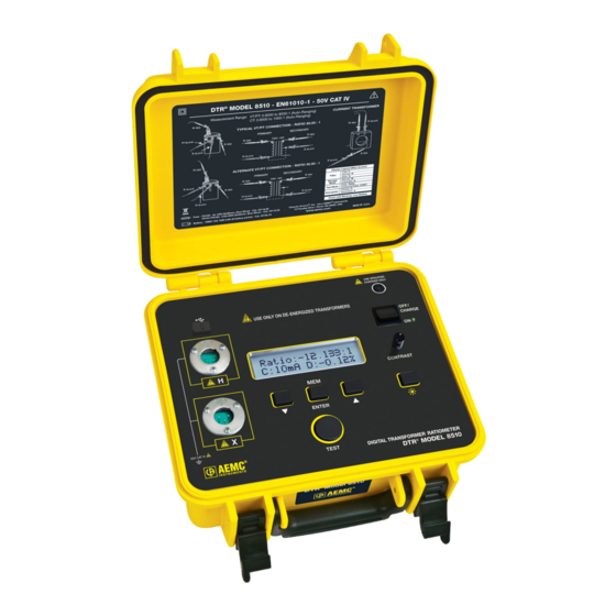
- Page 1 User Manual ENGLISH Digital Transformer Ratiometer (DTR ® Model 8510 TRANSFORMER RATIOMETERS WITH AEMC INSTRUMENTS ®...
- Page 2 Copyright Chauvin Arnoux , Inc. d.b.a. AEMC Instruments. All rights reserved. © ® ® No part of this documentation may be reproduced in any form or by any means (including electronic storage and retrieval or translation into any other language) without prior agreement and written consent from Chauvin Arnoux , Inc., as governed by United States and International copyright laws.
- Page 3 For recalibration, please use our calibration services. Refer to our repair and calibration section at www.aemc.com/calibration. Serial #: Catalog #: 2136.50 Model #: 8510 Please fill in the appropriate date as indicated: Date Received: Date Calibration Due: Chauvin Arnoux , Inc. ®...
-
Page 4: Table Of Contents
2.1 DESCRIPTION ................. 9 2.2 CONTROL FEATURES ..............10 2.3 CABLE IDENTIFICATION ..............11 3. SPECIFICATIONS ..............12 3.1 DTR 8510 SPECIFICATIONS ............12 ® 3.2 BATTERY CHARGER SPECIFICATIONS........13 4. DISPLAY FUNCTIONS ............14 4.1 PROGRAM FLOW ................. 14 4.2 TOP LEVEL MENU ................ 14 4.3 CONFIGURE INSTRUMENT ............ - Page 5 ® 7.2 OPENING THE CONTROL PANEL ..........38 7.3 USING THE CONTROL PANEL ........... 40 7.4 CONFIGURING THE DTR 8510 ..........42 ® 7.5 RUNNING A TEST ................. 44 7.6 DOWNLOADING A TEST .............. 45 7.7 SAVING THE MEASUREMENT RECORDS ....... 46 7.8 REPORT GENERATION ...............
-
Page 6: Introduction
Example: hardwired equipment in fixed installation and circuit breakers. CAT II: Corresponds to measurements performed on circuits directly connected to the electrical distribution system. Example: measurements on household appliances and portable tools. Digital Transformer Ratiometer (DTR ) Model 8510 - User Manual ®... -
Page 7: Precautions For Use
8510 . ® ■ The DTR 8510 must not be used in a manner in which any of its components ® (including test cables) are relied upon to provide protection from electric shock. No high voltage insulation/protection is provided by any component of the DTR 8510. -
Page 8: Ordering Information
Clip - Safety Alligator - Black (1000 V CAT IV, 15 A) ......Cat. #5000.99 Clip - Safety Alligator - Red (1000 V CAT IV, 15 A) ......Cat. #5000.00 Order Accessories and Replacement Parts Directly Online Check our Storefront at www.aemc.com/store for availability Digital Transformer Ratiometer (DTR ) Model 8510 - User Manual ®... -
Page 9: Product Features
ƒ Circuit Continuity ƒ Low Battery In addition, the DTR 8510 allows the user to store the data in automatic or ® manual mode after each test eliminating the need to write down the test results. Each measurement record is date and time stamped providing complete test information. -
Page 10: Control Features
NOTE: The DTR 8510 utilizes an advanced, low-voltage, step- ® down measurement technique in which the high voltage H windings are subjected to test excitation. This results in greater operator safety and the ability to test a much wider array of transformer types and sizes. -
Page 11: Cable Identification
BLACK INLINE PLUG Each cable is clearly marked. The Primary (H) cable has a 5-pin connector and the Secondary (X) cable has a 3-pin connector. They cannot inadvertently be connected incorrectly. Digital Transformer Ratiometer (DTR ) Model 8510 - User Manual ®... -
Page 12: Specifications
USB. 2.0 compliant, optically isolated, 115.2 KB Software DataView analysis software included ® MECHANICAL Dimensions (10.70 x 9.76 x 5.12) in (272 x 248 x 130) mm Weight 8.1 lbs (3.7 kg) Connection XLR connectors Digital Transformer Ratiometer (DTR ) Model 8510 - User Manual ®... -
Page 13: Battery Charger Specifications
(-4 to 104) °F (-20 to 40) °C SAFETY Insulation Class Electrical Safety Approval EN 60601-1, EN 60950, EN 60335-2-29 EMC Standards EN 61000-6-3 (Emission), EN 61000-6-1 (Immunity) Specifications are subject to change without notice. Digital Transformer Ratiometer (DTR ) Model 8510 - User Manual ®... -
Page 14: Display Functions
NOTE: The program flow is two or three levels deep at various points. The available choices for a level can be viewed by pressing the ▼ or ▲ keys. Digital Transformer Ratiometer (DTR ) Model 8510 - User Manual ®... -
Page 15: Configure Instrument
ƒ Select Language: Allows selection of language on the display (English, French, German, Italian, Spanish, Portuguese) NOTE: To move one level up and return to Configure Instrument, press the ▼▲ keys simultaneously. Digital Transformer Ratiometer (DTR ) Model 8510 - User Manual ®... -
Page 16: Set Clock
4.3.1 Set Clock 1. Within the top level of Configure Instrument, press the ▼ or ▲ key until Set Clock appears on the display, then press ENTER. Figure 4-5 Digital Transformer Ratiometer (DTR ) Model 8510 - User Manual ®... -
Page 17: Setup Nameplate
Nameplate values and Deviation will be displayed and stored in % relative to these values. The DTR 8510 allows the storage of 10 Nameplate voltages or ratios which can ® be individually selected for a given test. Digital Transformer Ratiometer (DTR ) Model 8510 - User Manual ®... - Page 18 To configure the settings for the Nameplate, perform the following: 1. Within the top level of Configure Instrument, press the ▼ or ▲ key until Setup Nameplate appears on the display, then press ENTER. Figure 4-9 Digital Transformer Ratiometer (DTR ) Model 8510 - User Manual ®...
- Page 19 ▼ or ▲ and then pressing the ENTER key. When the last digit on the Secondary is selected, the display returns to Setup Nameplate. Figure 4-13 Digital Transformer Ratiometer (DTR ) Model 8510 - User Manual ®...
-
Page 20: Select Test Type
4.3.4 Select Test Mode 1. From the top level of Configure Instrument, press the ▼ or ▲ key until Select Test Mode appears on the display, then press ENTER. Figure 4-15 Digital Transformer Ratiometer (DTR ) Model 8510 - User Manual ®... -
Page 21: Select Storage Mode
Measurement Record in the next available location. NOTE: If the DTR 8510 is connected to a computer, Auto mode ® will be disabled. The Measurement Record will not be saved in the instrument but will be sent to the computer. -
Page 22: Select Filter
High decimation results in lower noise but at a slower throughput rate. The calculation of arithmetic mean is a quick process at high clock speeds of the microprocessors. The DTR 8510 improves the quality of measurements in the following ways: ® ƒ Low noise electronics ƒ Shielded electronics and cables ƒ... -
Page 23: Erase Memory
Once the language is chosen, all the menu items, error messages etc. will be displayed in this language. The configuration retains the language if the instrument is turned OFF and then turned ON. Digital Transformer Ratiometer (DTR ) Model 8510 - User Manual ®... -
Page 24: Restoring Factory Defaults
4. Release the ▲ key when the instrument beeps. NOTE: The previously stored Measurement Records will remain in the memory and the language will remain the same as before the default configuration was loaded. Digital Transformer Ratiometer (DTR ) Model 8510 - User Manual ®... -
Page 25: Recall Data
2. Press the TEST button to move to second screen, which will display Current and Deviation %. Figure 4-22 3. Press the TEST button to move to the third screen to display the Date and Time. Figure 4-23 Digital Transformer Ratiometer (DTR ) Model 8510 - User Manual ®... - Page 26 Measurement Record at any location. NOTE: ƒ The DTR 8510 can store 99 OBJECTs. Each OBJECT can store ® up to 99 TESTs. ƒ In Manual mode, the user can select the location to store the Measurement Record.
-
Page 27: Operation
5. OPERATION WARNING: The DTR Model 8510 is designed for use on ® de-energized (dead) transformers only. Make sure the test sample is completely disconnected from AC power and is fully discharged. 5.1 POWER UP Turn the power switch to the ON position. -
Page 28: Running A Test
RATIO 2.767 : 1 SECONDARY PRIMARY 19920 : 7200CT BLACK BLACK BLACK BLACK - Alternate Connection RATIO 1.383 : 1 PRIMARY SECONDARY 19920 : 7200CT BLACK BLACK BLACK BLACK Figure 5-2 Digital Transformer Ratiometer (DTR ) Model 8510 - User Manual ®... - Page 29 1. Connect the Primary (H) and Secondary (X) cables to the appropriate connectors on the DTR 8510 and the transformer under test ® (see Fig. 5-2). 2. Press TEST button. The test will run continuity first and then run the ratio test.
-
Page 30: Storing The Measurement Record (Manual And Auto Mode)
NOTE: If the previously stored Measurement Record is encountered, the Auto store mode will skip over and store the new Measurement Record in the next available location. Digital Transformer Ratiometer (DTR ) Model 8510 - User Manual ®... -
Page 31: Vt/Pt Excitation Current
® continuity between its Secondary (X) and Primary (H) cables. ƒ The DTR 8510 will indicate OPEN for circuits >4 KΩ and CONT for circuits ® <4 KΩ. Check these values. A small fraction of transformers (High inductance or high winding Ohmic DC resistance) may appear open. - Page 32 1. Connect the Primary (H) cable to the appropriate connectors on the DTR ® Model 8510 and the transformer under test. Connect the Secondary (X) cable as a loop through the current transformer hole as shown in the figure. BLACK...
-
Page 33: Tips For Making Precise Ratio Measurements
Test Type. 5.3 TIPS FOR MAKING PRECISE RATIO MEASUREMENTS The DTR Model 8510 is designed for step-down transformers. It sources low ® voltage on the primary. It starts with a fraction of the final source voltage and checks the secondary voltage. - Page 34 2. Run VT/PT test. In this connection mode, the test results should yield a ratio nearly equal to 1.0000. If it does not, the DTR 8510 may require repair or re-calibration. ® 1 : 1 BLACK BLACK EQUIVALENT CONNECTIONS Figure 5-8...
-
Page 35: Connections
In the diagrams below, the top three are good connections but the bottom two should be avoided. Measurements - OK HR/HB XR/XB XR/XB XB/XR HB/HR XB/XR XR/XB XR/XB XB/XR Measurements - NOT OK XR/XB XB/XR XR/XB XB/XR XR/XB Digital Transformer Ratiometer (DTR ) Model 8510 - User Manual ®... -
Page 36: Polyphase Connections
RATIO WINDING WINDING WINDING WINDING 1 Ø 1 Ø ∆ ∆ ∆ ∆ √ ∆ H • ∆ √ H • ∆ √ X • ∆ √ X • Digital Transformer Ratiometer (DTR ) Model 8510 - User Manual ®... -
Page 37: Dataview ® Software
DataView Core, which is a requirement if you plan to create DataView reports. After you finish selecting and deselecting Control Panels and/or DataView Core, click Next. Digital Transformer Ratiometer (DTR ) Model 8510 - User Manual ®... -
Page 38: Opening The Control Panel
To open the Control Panel using the desktop icon: ƒ Double-click the DTR Icon in the DataView folder that was created during installation, located on the desktop. ƒ The Connection window will appear. Click OK. Figure 7-1 Digital Transformer Ratiometer (DTR ) Model 8510 - User Manual ®... - Page 39 Quick ® Start dialog box will appear (see Fig. 7-2). Figure 7-2 Select Configure Instrument. The Select Instrument dialog box will appear. Figure 7-3 Digital Transformer Ratiometer (DTR ) Model 8510 - User Manual ®...
-
Page 40: Using The Control Panel
Print Preview - Provides a preview of the selected test to be printed Print All Tests - Prints all the tests in the selected Object Print - Prints the selected real-time window Digital Transformer Ratiometer (DTR ) Model 8510 - User Manual ®... - Page 41 Help Topics - Displays the Control Panel help topic About DTR - Displays a dialog box providing the current version number of the DTR 8510 and DataView software ® ® Digital Transformer Ratiometer (DTR ) Model 8510 - User Manual ®...
-
Page 42: Configuring The Dtr ® 8510
Default Storage Mode: Allows selection of storage of each Measurement Record in Manual or Automatic mode. Default Nameplate Values: Allows the user to store the most frequently used nameplate values (or ratio values). Digital Transformer Ratiometer (DTR ) Model 8510 - User Manual ®... - Page 43 Read from Instrument: Allows the present configuration to be read. Cancel: Cancels the process to modify the configuration and closes the dialog box. NOTE: Parameters changed after Write to Instrument was executed will be lost. Digital Transformer Ratiometer (DTR ) Model 8510 - User Manual ®...
-
Page 44: Running A Test
NOTE: ƒ If the DTR 8510 is in Autosave mode, the connection to the computer will ® disable the automatic saving of the Measurement Record. ƒ If the Test needs to be cancelled while testing is in progress, press the TEST button on the instrument or CANCEL button on the screen. -
Page 45: Downloading A Test
This dialog box displays the content of the memory. No Measurement Records are downloaded as yet. 1. Select the Measurement Records individually or press Select All. Press Download to get the data to the computer. Figure 7-9 Digital Transformer Ratiometer (DTR ) Model 8510 - User Manual ®... -
Page 46: Saving The Measurement Records
To generate a report, a file needs to be open. 1. Select Open from the File menu. If necessary, navigate to the appropriate folder where the .icp file is located, select it and press Open. Figure 7-11 Digital Transformer Ratiometer (DTR ) Model 8510 - User Manual ®... - Page 47 , refer to the ® DataView manual that is included on the installation CD. This ® manual can also be found online at www.aemc.com on our software download page for DataView ® Digital Transformer Ratiometer (DTR ) Model 8510 - User Manual ®...
-
Page 48: Maintenance
■ Use caution with metallic tools that may short battery packs, power supplies, etc. 8.1 CHARGING THE BATTERIES The DTR 8510 is supplied with an external smart charging unit. In order to ® charge the NiMH battery packs, the instrument switch must be in the OFF/ CHARGE position. - Page 49 NOTE: ƒ The DTR 8510 Power Switch must be in the OFF/CHARGE position in order ® for the unit to charge. ƒ The DTR 8510 cannot be used to test while it is charging. ® ƒ There is no indication on the front panel about the status of charging or its completion.
-
Page 50: Cleaning
■ Use a soft cloth lightly moistened with soapy water. ■ Wipe with a moist cloth and then dry with a dry cloth. ■ Never use alcohol, solvents or hydrocarbons. Digital Transformer Ratiometer (DTR ) Model 8510 - User Manual ®... -
Page 51: Repair And Calibration
Chauvin Arnoux , Inc. d.b.a. AEMC Instruments ® ® Phone: (800) 343-1391 (Ext. 351) Fax: (603) 742-2346 E-mail: techsupport@aemc.com www.aemc.com Digital Transformer Ratiometer (DTR ) Model 8510 - User Manual ®... -
Page 52: Limited Warranty
(603) 742-2346 E-mail: repair@aemc.com Caution: To protect yourself against in-transit loss, we recommend that you insure your returned material. NOTE: You must obtain a CSA# before returning any instrument. Digital Transformer Ratiometer (DTR ) Model 8510 - User Manual ®... -
Page 53: Display Messages
All the buttons will be non-operational now. The batteries must be recharged in order to continue testing. NOTE: The DTR Model 8510 charges in < 4 h. The instrument can ® not be used to test when the batteries are charging. - Page 54 Measurement Records cannot be stored or recalled because the memory cannot be accessed. Factory service is needed. However, the DTR 8510 can be used ® to make measurements in a normal manner. Digital Transformer Ratiometer (DTR ) Model 8510 - User Manual ®...
-
Page 55: Transformer Serial Number Correlation To Object Number
TRANSFORMER SERIAL NUMBER CORRELATION TO OBJECT NUMBER Transformer Serial Number Correlation to Object Number Object # # of Tests in Object Transformer Serial # (1 - 99) (1 - 99) Digital Transformer Ratiometer (DTR ) Model 8510 - User Manual ®... - Page 56 05/24 99-MAN 100353 v11 AEMC Instruments ® 15 Faraday Drive • Dover, NH 03820 USA Phone: +1 (603) 749-6434 • +1 (800) 343-1391 • Fax: +1 (603) 742-2346 www.aemc.com © 2010 Chauvin Arnoux , Inc. d.b.a. AEMC Instruments. All Rights Reserved. ®...
Need help?
Do you have a question about the 8510 and is the answer not in the manual?
Questions and answers