
Subscribe to Our Youtube Channel
Related Manuals for Bartec SILAS A7-3741-1110 Series


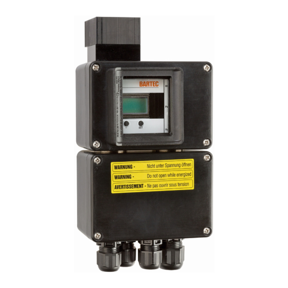
Summary of Contents for Bartec SILAS A7-3741-1110 Series
- Page 1 Operating instructions Steuerung SILAS Control unit Type: A7-3741-1110/..; Pressure monitor Type: 17-51P3-1604 Document no.: A1-3741-7D0001 Version: 31 March 2017 / Rev. F...
- Page 2 Version: 30. June 2017 / Rev. F Contents Germany English 1 - 60 Appendix EU Declaration of Conformity BARTEC GmbH Tel.: +49 7931 597-0 info@bartec.de Reservation: Technical data subject to change without Max Eyth-Straße 16 Fax: +49 7931 597-119 www.bartec.de notice.
- Page 3 - EMPTY PAGE -...
-
Page 4: Table Of Contents
SILAS Control Unit Table of Contents Type A7-3741-1110/..Safety This Manual 1.1.1 Languages Handling the Product Use in Accordance with the Intended Purpose 1.3.1 Exclusive Purpose 1.3.2 Improper Use Operator’s Obligations Safety Instructions 1.5.1 General Safety Instructions 1.5.2 Safety Instructions for Operation Standards Conformed To Ex Protection Type and Certification Warranty... - Page 5 SILAS Control Unit Table of Contents Type A7-3741-1110/**** Changing of Levels Commissioning General Settings for Commissioning 6.1.1 Purging Function 6.1.2 K3 Relay Commissioning of the SILAS Controller for Zone 2 6.2.1 Defining the Operating Pressure 6.2.2 Determination of the purging pressure 6.2.3 Purge time Calculate 6.2.4...
-
Page 7: Safety
This manual is an integral part of the scope of supply even if for logistical reasons it can be ordered and delivered separately. If you need any further information, please ask the BARTEC branch that is near you or responsible for your area. Particularly important points in this documentation are marked with a warning symbol:... -
Page 8: Languages
The operating instructions are available in various languages. They are enclosed with the product in the languages German, English, French, Italian, Spanish and Russian. If you require any other languages, please ask BARTEC or request them when placing the order. -
Page 9: Safety Instructions
SILAS Control Unit Safety Type A7-3741-1110/..Safety Instructions 1.5.1 General Safety Instructions Do not wipe devices with a dry cloth or clean them in a hazardous area! Do not open devices in a hazardous area. The general statutory regulations or directives relating to safety at work, accident prevention and environmental protection legislation must be observed, e.g. -
Page 10: Standards Conformed To
SILAS Control Unit Safety Type A7-3741-1110/..Standards Conformed To The SILAS control unit conforms to Directive 94/9/EC for devices and protective systems for use for their intended purpose in hazardous areas (ATEX Directive). Pursuant to this directive, the following standards serve as a basis for the SILAS control unit: Standard Designation Explosive atmospheres -... -
Page 11: Ex Protection Type And Certification
SILAS Control Unit Safety Type A7-3741-1110/..Ex Protection Type and Certification The devices are certified for installation in the following areas: ATEX (Europe) Ex type of protection II 3 G Ex nA nC [pzc] IIC T4 Gc II 3 G Ex nA nC [pzc] IIC T6 Gc II 3 D Ex tc [pzc] IIIB T85 °C Dc Certification TÜV 09 ATEX 553359 X... -
Page 12: Warranty
SILAS Control Unit Safety Type A7-3741-1110/..Warranty Warning No modifications or conversions may be made unless the manufacturer gives his approval in writing. Explosion protection will no longer be ensured if non-specified components are used. It cannot be guaranteed that parts procured from other suppliers will have been designed and produced in conformance with safety requirements and with the necessary stress tolerance. -
Page 13: Product Description
SILAS Control Unit Product Description Type A7-3741-1110/..Product Description “Pressurised Enclosure” Type of Protection The Ex p type of protection, referred to as “pressurised enclosure”, is based on the measure of purging out any explosive gases that are in a closed enclosure and then generating and maintaining a level of pressure that is higher than that of the ambient atmosphere. -
Page 14: Schematic Diagram Of The Silas Controller In Zone
SILAS Control Unit Product Description Type A7-3741-1110/..Schematic Diagram of the SILAS Controller in Zone 2 Item Designation Purge gas flow Pressurised enclosure SILAS control unit Purge gas valve with purge gas nozzle (purging flow restriction) ... - Page 15 SILAS Control Unit Product Description Type A7-3741-1110/..Schematic Diagram of the SILAS Controller in Zone 22 Position Designation Purge gas flow Pressurised enclosure SILAS control unit Pressure reducer with pressure gauge Pressure monitor module Page 14 of 60 Technical data subject to change without notice.
-
Page 16: Silas Control Unit
SILAS Control Unit Product Description Type A7-3741-1110/..SILAS Control Unit Warning Processes with high electromagnetic radiation. The SILAS control unit must not be mounted in areas in which high levels of electromagnetic radiation can arise. Inspect the site of installation for electromagnetic radiation. The SILAS control unit can be mounted inside or outside the pressurised enclosure. -
Page 17: Pressure Monitor
SILAS Control Unit Product Description Type A7-3741-1110/..Pressure Monitor DANGER DANGER due to deposits of dust. When used in Dust Ex applications, deposits of dust can build up in the pressure monitor. If a lot of dust accumulates, clean the pressure monitor twice a year. The pressure monitor has two functions inside the SILAS control. -
Page 18: Pressure Reducer With Pressure Gauge
SILAS Control Unit Product Description Type A7-3741-1110/..Pressure Reducer with Pressure Gauge Attention Material damage when the maximum permissible internal pressure is exceeded in the pressurised enclosure. If the supply pressure is set at too high a level, there is a risk of destroying the pressurised enclosure. -
Page 19: Mounting Kit For Internal Installation
SILAS Control Unit Product Description Type A7-3741-1110/..2.11 Mounting Kit for Internal Installation The mounting kit for internal installation is necessary if the SILAS control unit is fitted into a pressurised enclosure. In this case, the reference connection for atmospheric pressure is conducted outwards by means of a hose line. -
Page 20: Installation
SILAS Control Unit Installation Type A7-3741-1110/..Installation The SILAS controller can be mounted in various installation positions on the pressurised enclosure. The positioning of the SILAS controller on the pressurised enclosure is described in the following chapter. The SILAS control unit can be mounted in the interior or on the exterior of the pressurised enclosure. -
Page 21: Silas Controller - External Mounting
SILAS Control Unit Installation Type A7-3741-1110/..SILAS Controller - External Mounting 3.2.1 Control Configuration DANGER Death or serious physical injury if the purge gas supply and the pressure monitor outlet are installed incorrectly. This interferes with the purging action in the pressurised enclosure. Gas bubbles can form inside the pressurised enclosure and lead to an explosion when the installed parts are activated. -
Page 22: Installation Of The Control Unit
SILAS Control Unit Installation Type A7-3741-1110/..3.2.2 Installation of the Control Unit To install the SILAS control unit, the boreholes must be made at the desired point in the pressurised enclosure as shown in the drilling pattern in the appendix. To mount the SILAS control unit onto a surface, it is first necessary to remove the lower lid. -
Page 23: Schematic Diagram Of The Silas Controller In Zone
SILAS Control Unit Installation Type A7-3741-1110/..SILAS Controller - Internal Mounting 3.3.1 Control Configuration DANGER Death or serious physical injury if the purge gas supply and the pressure monitor outlet are installed incorrectly. This interferes with the purging action in the pressurised enclosure. Gas bubbles can form inside the pressurised enclosure and lead to an explosion when the installed parts are activated. -
Page 24: Mounting The Control Unit
SILAS Control Unit Installation Type A7-3741-1110/..3.3.2 Mounting the Control Unit The SILAS control unit is screwed to the mounting plate using the mounting fixtures integrated in the enclosure. For this purpose, the SILAS control unit is affixed to the mounting plate using four M4 screws. -
Page 25: Mounting Atmosphere Measuring Point
SILAS Control Unit Installation Type A7-3741-1110/..3.3.3 Mounting Atmosphere Measuring Point Attention Protect the atmosphere measuring point from dirt. Dirt on the atmosphere measuring point causes faulty measurements of operating pressure levels. As a result of the faulty measurement, the pressurised enclosure is deactivated and cannot be operated. -
Page 26: Mounting Pressure Monitor
SILAS Control Unit Installation Type A7-3741-1110/..Mounting Pressure Monitor Warning Death or risk of injury due to excessive internal pressure in the pressurised enclosure. The enclosure can be destroyed. Make sure the outlet threaded connection is not covered from the outside. -
Page 27: Purge Gas Supply
SILAS Control Unit Installation Type A7-3741-1110/..Purge Gas Supply Attention Material damage caused by the absence of a purge gas nozzle. Due to the build-up of internal pressure there is a risk of excessive strain on the pressurised enclosure. Check if the purge gas nozzle is there. Note Not enough purge gas because the purge gas supply line is too small. -
Page 28: Installation Of The G1/4" Purge Gas Supply
SILAS Control Unit Installation Type A7-3741-1110/..3.5.1 Installation of the G1/4″ Purge Gas Supply The purge gas supply must be installed carefully. To ensure that the screwed parts are leak-tight, they can be sealed with Teflon® tape. Care must be taken to prevent the penetration of foreign particles during assembly. ... -
Page 29: Mounting Of The G1/2" Purge Gas Supply
SILAS Control Unit Installation Type A7-3741-1110/..3.5.2 Mounting of the G1/2″ Purge Gas Supply The purge gas supply must be installed carefully. To ensure that the screwed parts are leak-tight, they can be sealed with Teflon® tape. Care must be taken to prevent the penetration of foreign particles during assembly. ... -
Page 30: Installation Of The Purge Gas Supply For Enclosures Used In Dust Explosion-Endangered Areas
SILAS Control Unit Installation Type A7-3741-1110/..3.5.3 Installation of the Purge Gas Supply for Enclosures Used in Dust Explosion-Endangered Areas The purge gas supply must be installed carefully. To ensure that the screwed parts are leak-tight, they can be sealed with Teflon® tape. Care must be taken to prevent the penetration of foreign particles during assembly. -
Page 31: Connections
SILAS Control Unit Connections Type A7-3741-1110/..Connections Pneumatic Connections When the SILAS controller is used, an atmosphere measuring lead need be fitted only in the “internal installation” version. This serves to correctly measure the positive pressure inside the pressurised enclosure. You will find installation details in the “Mounting the Atmosphere Measuring Point”... -
Page 32: Electrical Connections
SILAS Control Unit Connections Type A7-3741-1110/..Electrical Connections 4.2.1 Safety Instructions for the Electrical System DANGER Death or serious physical injury due to work on live parts. Risk of fatal injury from electric current. Observe the 5 safety rules for work on electrical systems: disconnect from mains;... -
Page 33: Electrical Connections To The Silas Control Unit
SILAS Control Unit Connections Type A7-3741-1110/..4.2.3 Electrical Connections to the SILAS Control Unit Attention Avoid damage to the sealings. Cancellation of the Ex protection strategy. When closing the SILAS control unit, visually check the sealing (intactness, cleanliness and secure fitting). Attention Damage to the controller resulting from insulation measurement. -
Page 34: Operation
Steuergerät SILAS Operation Typ A7-3711-.2../..Operation Setting of Parameters The parameters are set via the SILAS operating menu. For this purpose, there are three buttons and one rotary switch on the SILAS control unit. ... -
Page 35: And "Set" Buttons
SILAS Control Unit Operation Type A7-3741-1110/..“+”, “-“ and “SET” Buttons The “+” (), “-“ () and “SET” () buttons serve to change and save the switching levels selected by the “Parameters” rotary switch (). Pressing the “+” or “–“ key once alters the level by 0.1 mbar. The saved level is marked by an “*”. -
Page 36: Commissioning
Steuergerät SILAS Commissioning Typ A7-3711-.2../..Commissioning General Settings for Commissioning 6.1.1 Purging Function Various purging functions can be assigned to the SILAS control unit to suit the application. The behaviour of the SILAS control unit changes depending on the purging function selected. -
Page 37: Commissioning Of The Silas Controller For Zone 2
SILAS Control Unit Commissioning Type A7-3741-1110/..Commissioning of the SILAS Controller for Zone 2 Procedure for Commissioning Before commissioning, check the electrical devices installed inside the pressurised enclosure. Make sure the pressurised enclosure is purged sufficiently. The relevant safety regulations and rules must be observed. ... -
Page 38: Determination Of The Purging Pressure
Steuergerät SILAS Commissioning Typ A7-3711-.2../..6.2.2 Determination of the purging pressure To determine the purging pressure, close the pressurised enclosure and put the SILAS control unit into operation. Procedure: Set the “ON/OFF” rotary switch to position 1. Set the “Parameters” rotary switch to position 5. ... -
Page 39: Checking The Purging Phase
SILAS Control Unit Commissioning Type A7-3741-1110/..Example of how to calculate purge time: Cabinet capacity = 140 l Purging = 5 times Set the “P3” = 12.0 mbar switching level” as described in Chapter 6.2.2 “Determination of the purging pressure “. Flow in accordance with diagram = 14,000 l/h Quantity factor with 1 pressure monitor = 60;... -
Page 40: Checking The Operating Phase
Steuergerät SILAS Commissioning Typ A7-3711-.2../..6.2.5 Checking the Operating Phase When commissioning the pressurised enclosure, it is necessary to check the individual operating phases. For this purpose, all preceding work steps must be completed. The operating pressure, leakage compensation and purge time must be set. Procedure: ... -
Page 41: Commissioning Of The Silas Controller For Zone 22
SILAS Control Unit Commissioning Type A7-3741-1110/..Commissioning of the SILAS Controller for Zone 22 Procedure for commissioning: Before commissioning, check the electrical devices installed inside the pressurised enclosure. Make sure the pressurised enclosure is purged sufficiently. The relevant safety regulations and rules must be observed. ... -
Page 42: Adjusting The Leakage Air Needle
Steuergerät SILAS Commissioning Typ A7-3711-.2../..Adjusting the Leakage Air Needle The leakage air needle for the digital purge gas valve must be adjusted during commissioning or when altering the leakage air quantity. Procedure Set the “ON/OFF” rotary switch to position “1”. ... -
Page 43: Safety During Operation
SILAS Control Unit Commissioning Type A7-3741-1110/..Safety during Operation DANGER Damage to the explosion protection measure. If it can be assumed that safe operation is no longer possible, the SILAS control unit must be put out of operation and secured against restarting. Types of Purge gas DANGER Risk of suffocation when using inert gas as a purge gas. -
Page 44: Operation
Steuergerät SILAS Operation Typ A7-3711-.2../..Operation Operating Phases of the SILAS Controller for Zone 2 The operation of a pressurised enclosure constructed for explosive gas atmospheres can be divided into three phases. The three phases break down into the preparatory, purging and operating phases. -
Page 45: Purging Phase
SILAS Control Unit Operation Type A7-3741-1110/..Purging Phase Attention Interruption of the purge time. If the pressure levels drop below or exceed the specified pressure setpoints, the purge time for the SILAS control unit stops. Check the purge gas supply. ... -
Page 46: Operating Phases Of The Silas Controller For Zone 22
SILAS Control Unit Operation Type A7-3741-1110/..Operating Phases of the SILAS Controller for Zone 22 The operation of a pressurised enclosure constructed for explosive dust atmospheres can be divided into two phases: the preparatory and operating phases. 7.5.1 Flow Diagram Operating phase Requirements Effect... -
Page 47: Bypass-Operation During The Operating Phase
SILAS Control Unit Operation Type A7-3741-1110/..Bypass-Operation During the Operating Phase DANGER Risk of explosion during active bypass operation. The activation of the bypass operation can cause explosive gas to penetrate the pressurised enclosure. Determination of the concentration of gas in the surrounding atmosphere. -
Page 48: Maintenance And Care
SILAS Control Unit Maintenance and Care Type A7-3711-.2../..Maintenance and Care Note Maintenance intervals Regular maintenance is not necessary if the device is operated appropriately in compliance with the installation instructions and ambient conditions. The recommendation is: An inspection every year in accordance with the table in Chapter 8.1. -
Page 49: Inspection Table For Commissioning And Maintenance
SILAS Control Unit Maintenance and Care Type A7-3741-1110/..Inspection Table for Commissioning and Maintenance Main- Commissioning tenance Item Inspection point Visual inspection for damage Attachment of the SILAS control unit according to the manual Diagonal purging of enclosure assured Check that the fitted devices are fastened securely. Sufficient purging of installed devices Note devices with integrated capacitors (it may be necessary to affix a sign) -
Page 50: Malfunctioning And Troubleshooting
SILAS Control Unit Malfunctioning and Troubleshooting Type A7-3711-.2../..Malfunctioning and Troubleshooting It is assumed here that all external electrical and mechanical units have been connected correctly. For that reason, it should first be checked that the electrical units have indeed been set up and connected properly. - Page 51 SILAS Control Unit Malfunctioning and Troubleshooting Type A7-3741-1110/..Fault Possible Cause Remedy Digital purging gas Internal pressure drops below P2, Fix leaks. valve does not close Losses through leakage are too after the purging high. phase. Control unit switches The leakage air needle for the Increase the air flow rate electrical devices off digital valve is too small...
-
Page 52: Technical Data
SILAS Control Unit Technical Data Type A7-3741-1110/..Technical Data 10.1 SILAS Control Unit Parameters Specifications Type A7-3741-1110/.00. Ambient temperature during -20 °C to +60 °C storage and transport Ambient temperature during -20 °C to +60 °C (T4) operation -20 °C to +40 °C (T6) Dimensions 110 x 188 x 55.5 mm (WxHxD) Material... -
Page 53: Pressure Monitor
SILAS Control Unit Technical Data Type A7-3741-1110/..10.2 Pressure Monitor Parameters Specifications Type 17-51P3-1604 Dimensions 55 x 70 x 57 mm (WxHxD) Material Opening pressure 3 mbar Mounting borehole 37 mm Weight Approx. 0.2 kg Ambient temperature storage -20 °C to + 80 °C Ambient temperature operation -20 °C to + 80 °C See product data sheet for more technical data... -
Page 54: Silas Control Purge Gas Diagram
SILAS Control Unit Technical Data Type A7-3741-1110/..10.5 SILAS Control Purge Gas Diagram The following flow rate diagram relates to the SILAS control. Page 53 of 60 Techncal data subject to change without notice. -
Page 55: Order Numbers
SILAS Control Unit Order Numbers Type A7-3741-1110/..Order Numbers 11.1 SILAS Control Unit SILAS control unit, AC 230 V, ATEX and TÜV marking A7-3741-1110/1000 SILAS control unit, AC 115 V, ATEX and TÜV marking A7-3741-1110/2000 SILAS control unit, DC 24 V, ATEX and TÜV marking A7-3741-1110/4000 SILAS control unit, AC 230 V, ATEX and TÜV marking A7-3741-1110/1002... -
Page 56: Appendix
SILAS Control Unit Appendix Type A7-3741-1110/..Appendix 12.1 Borehole Pattern for the SILAS Control Unit Page 55 of 60 Techncal data subject to change without notice. -
Page 57: Test And Assessment Report Form
SILAS Control Unit Appendix Type A7-3741-1110/..12.2 Test and Assessment Report Form Test report/checklist for Ex pz/p operating equipment Part: Customer: Type: Order: Installation of the Ex p operating equipment in: Zone 2 (Ex pz) Zone 22 (Ex p) Characteristics of the Ex pz/p operating equipment Serial number Mains voltage Power dissipation... - Page 58 SILAS Control Unit Appendix Type A7-3741-1110/..Characteristics of the SILAS control unit Rotary switch Parameters Description Switching level S2 in position. The type of function must be selected as in Function the “Purging Function” chapter. Purge time The purge time is Minimum pressure in enclosure higher than mbar atmospheric pressure (switching-off level)
-
Page 59: Declaration Of Conformity And Approvals
SILAS Control Unit Declaration of Conformity and Approval Type A7-3741-1110/..Declaration of Conformity and Approvals 13.1 Declaration of Conformity Page 58 of 60 Technical data subject to change without notice. - Page 60 SILAS Control Unit Notes Type A7-3741-1110/..Page 59 of 60 Techncal data subject to change without notice.
- Page 61 SILAS Control Unit Notes Type A7-3741-1110/..Page 60 of 60 Technical data subject to change without notice.
- Page 62 Your partner for safety technology. Challenge us! BARTEC GmbH Max-Eyth-Str. 16 97980 Bad Mergentheim Germany Phone: +49 7931 597 0 info@bartec.de www.bartec.de...
Need help?
Do you have a question about the SILAS A7-3741-1110 Series and is the answer not in the manual?
Questions and answers