
Subscribe to Our Youtube Channel
Related Manuals for Bartec SILAS A7-3741-1110 Series


Summary of Contents for Bartec SILAS A7-3741-1110 Series
- Page 1 1021284 Operating Instructions SILAS Controller A7-3741-1110/…. Version 2.00 Max-Eyth-Straße 16 Phone: 07931 597-0 E-Mail: info@bartec.de GmbH Germany 97980 Bad Mergentheim Fax: 07931 597-160 Internet:http://www.bartec.de...
-
Page 2: Table Of Contents
Operating Instructions Controller for Zones 2 and 22 SILAS Version 2.00 Page 2 of 28 Table of Contents System Components ..........................3 Information on the Operating Instructions....................4 Warranty ..............................5 Instructions on the Installation of the SILAS Controllers ............... 6 Safety Instructions ........................ -
Page 3: System Components
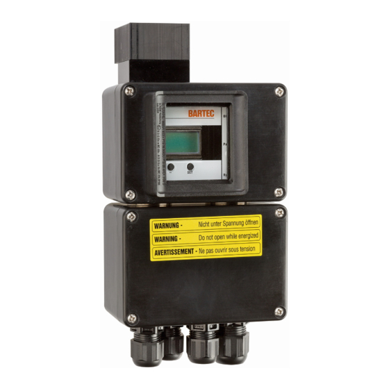
SILAS pressure control device leakage needle valve Controller of BARTEC is a controller for monitoring pressure in control panels in zone 2 and zone 22 Ex SILAS areas. It controls the protective gas quantities for a closed control panels and accordingly generates an Ex-free area inside the closed control panel. -
Page 4: Information On The Operating Instructions
This manual is an integral part of the scope of supply even if it can be ordered and/or delivered separately for reasons of logistics. If you need any further Information, please ask the BARTEC branch that is near you or responsible for your area. -
Page 5: Warranty
Operating Instructions Controller for Zones 2 and 22 SILAS Version 2.00 Page 5 of 28 Warranty As a basic rule, our “General Conditions of Sale and Delivery” apply. These are available to the owner-operator at the latest when the contract is concluded. Warranty and liability claims for personal injury and damage to property are excluded if they are due to one or more of the following reasons: Inappropriate assembly, commissioning, operation and maintenance of the SILAS... -
Page 6: Instructions On The Installation Of The Silas Controllers
Operating Instructions Controller for Zones 2 and 22 SILAS Version 2.00 Page 6 of 28 Instructions on the Installation of the SILAS Controllers Safety Instructions For electrical installations the relevant installation and operation regulations must be followed! (e.g. Directive 1999/92/EC, Directive 94/9EC, German Ordinance on Industrial Safety and Health (BetrSichV) and the national regulations that are in force, IEC/EN 60 079-14 and VDE 0100). -
Page 7: General Data
Operating Instructions Controller for Zones 2 and 22 SILAS Version 2.00 Page 7 of 28 General Data The user is merely permitted to carry out the necessary wiring work on the terminals accessible to him. •• Any further dismantling may only be done by the manufacturer or by persons authorised by the manufacturer. -
Page 8: Description Of The System
Operating Instructions Controller for Zones 2 and 22 SILAS Version 2.00 Page 8 of 28 Description of the System SILAS Controller can be used in combination with the pressure control device and the digital purge valve for all normal applications (control panels, control enclosures, printers, operator terminals etc.) in Ex zone 2 and Ex zone 22. Use in Ex Zone 2 The user decides on his own responsibility about the use of a purging cycle. -
Page 9: Use In Ex Zone 22
Operating Instructions Controller for Zones 2 and 22 SILAS Version 2.00 Page 9 of 28 After the end of the purging time, the operating phase is initiated by the following measures: The purge valve closes and the leakage losses are compensated by means of the integrated leakage air •... -
Page 10: Assembly
Operating Instructions Controller for Zones 2 and 22 SILAS Version 2.00 Page 10 of 28 Assembly The system configuration makes assembly at the control panel easy. For this purpose the SILAS Controller is mounted on the outside of the control panel. The internal pressure is monitored via a 13-mm through hole and sealed by means of the bulkhead screw connection. -
Page 11: Technical Data For The Silas System Components
Operating Instructions Controller for Zones 2 and 22 SILAS Version 2.00 Page 11 of 28 Technical Data for the SILAS System Components SILAS Controller Types A7-3741-1..0/..Marking II 3G Ex nAC [pz] II T4 -20 °C + 60 °C ≤ T ≤... - Page 12 Operating Instructions Controller for Zones 2 and 22 SILAS Version 2.00 Page 12 of 28 Dimensions and Fastening Drill Holes Included in the scope of supply: 1a: SILAS controller 1b: Bulkhead screw connection R1/4" x R1/8" 1c: Sealing brass dia. 13mm 1d: Sealing polyamide dia.
-
Page 13: Silas Pressure Control Device
Operating Instructions Controller for Zones 2 and 22 SILAS Version 2.00 Page 13 of 28 SILAS Pressure Control Device Type 17-51P3-1604 Dimensions 55 x 70 x 56 mm Opening pressure 5 mbar Control panel borehole 37 mm Weight approx. 0.2 kg Dimensions for the SILAS pressure control device wall of cabinet Purge gas... -
Page 14: Silas Purge Valve Including Leakage Needle Valve
Operating Instructions Controller for Zones 2 and 22 SILAS Version 2.00 Page 14 of 28 SILAS Purge Valve including Leakage Needle Valve Type 03-5110-0026 mains voltage AC 230 V 03-5100-0028 mains voltage AC 115 V 03-5110-0029 mains voltage DC 24 V Dimensions 90 x 60 x 96 mm Min. -
Page 15: Adjustment Of The Leakage Needle Valve
Operating Instructions Controller for Zones 2 and 22 SILAS Version 2.00 Page 15 of 28 7.3.4 Adjustment of the Leakage Needle Valve The leakage needle valve integrated in the purge valve can be adjusted at any time to the quantity required to compensate for the leakage losses. -
Page 16: Pressure Reducer ¼" And Leakage Needle Valve
Operating Instructions Controller for Zones 2 and 22 SILAS Version 2.00 Page 16 of 28 Pressure Reducer ¼” with Leakage Needle Valve Pressure reducer ¼” with Leakage 05-0056-0015 needle valve Control panel borehole 17 mm Maximum input pressure 25 bar Adjustable initial pressure 0-6 bar Material... -
Page 17: Assembly Set For The Internal Fitting Of The Silas Controller
Operating Instructions Controller for Zones 2 and 22 SILAS Version 2.00 Page 17 of 28 Assembly Set for the Internal Fitting of the SILAS Controller The assemblöy set will be used when the SILAS-Controller has to be mounted inside the Ex pz panel. In this case the conection for the referenz of the atmosphaerepressure has to be directed with a tube to the outside. -
Page 18: Circuit Diagram
Operating Instructions Controller for Zones 2 and 22 SILAS Version 2.00 Page 18 of 28 Circuit Diagram Circuit Diagram Parameter ON/OFF µ-Controller Yellow Green Yellow LED 1 LED 2 LED 3 SI 1 Purge valve Operate Alarm Power supply Changing the SI 1 Fuse for the Purge Valve SILAS Controller's junction box has a fuse holder for a 5 x 20 mm fuse. -
Page 19: Parameter Settings
Operating Instructions Controller for Zones 2 and 22 SILAS Version 2.00 Page 19 of 28 Parameter Settings The S 1 rotary switch switches the SILAS Controller on. The parameter display is selected by turning the S 2 rotary switch. The setting parameters are changed with the “+” and “-“ keys. They are saved by pressing the “SET” key. The saved value is marked by a “... -
Page 20: S 2 Rotary Switch
Operating Instructions Controller for Zones 2 and 22 SILAS Version 2.00 Page 20 of 28 S 2 Rotary Switch The following functions are assigned to the respective position of the S 2 rotary switch: Position Function Display Aktion Purge time is Purge time Purge... - Page 21 Operating Instructions Controller for Zones 2 and 22 SILAS Version 2.00 Page 21 of 28 K 2 + Operate Switches simultaneously with K2 P 1 + MIN-Alarm Switches on if the P 1 pressure value is exceeded. P 1 - MIN-Alarm Switches off if the value falls short of the P 1 pressure.
-
Page 22: Relay Connection
Operating Instructions Controller for Zones 2 and 22 SILAS Version 2.00 Page 22 of 28 Relay Connection 10.1 K1 Relay The K1 relay serves to actuate a digital purge valve. The necessary back-up fuse for a purge valve is integrated in the connection chamber of the Controller. -
Page 23: Bypass Bridge
Operating Instructions Controller for Zones 2 and 22 SILAS Version 2.00 Page 23 of 28 Bypass Bridge If S 2 is at pos. 9 and the “bypass” bridge is set, K 2 relay switches on. The bypass function is deactivated by removing the bypass bridge or altering the S 2 switch position. -
Page 24: Purging Time Calculation
Operating Instructions Controller for Zones 2 and 22 SILAS Version 2.00 Page 24 of 28 Purging Time Calculation If the overpressure-monitored control panel is equipped with a type 17-51P3-1604 pressure control device to monitor an automatic pre-purging cycle, the pre-purging time can be determined. A precondition is the positioning of the pressure control device in accordance with the chapter on “Assembly”... -
Page 25: Malfunctioning
Operating Instructions Controller for Zones 2 and 22 SILAS Version 2.00 Page 25 of 28 Malfunctioning It is assumed here that the connection of all external electrical and mechanical units has been carried out in orderly fashion. For that reason it should be checked that the electrical units have indeed been set up and connected properly. Fault Possible cause Remedy... - Page 26 Operating Instructions Controller for Zones 2 and 22 SILAS Version 2.00 Page 26 of 28 Inspection and Testing Report /Checklist for the SILAS Combi-Panel type A7-3702-.1.../..Part: SILAS Combi-Panel (SCC) Customer: Type: A7-3702-1100/_________________(Order no.) Site of installation: Installation of SCC in: Zone 2 Zone 22 Characteristics of the SCC Serial no.
- Page 27 SILAS does not emit an alarm or SCC does not switch off. Comments: Tester: Date: BARTEC GmbH Test mark: Max Eyth Straße 16 D - 97980 Bad-Mergentheim Tel.: 07931/ 597-0 SILAS_E_110806.doc Operating Instructions for the SILAS Controller • Technical data are subject to change...
-
Page 28: Order Numbers
Operating Instructions Controller for Zones 2 and 22 SILAS Version 2.00 Page 28 of 28 Order Numbers Order Number SILAS Controller A7-3741-1110/1000 Supply voltage: AC 230 V; pressure range 0-25 mbar SILAS Controller A7-3741-1110/2000 Supply voltage: AC 115 V; pressure range 0-25 mbar SILAS Controller A7-3741-1110/4000... - Page 29 Appendix A to the Operating Instructions Controller SILAS Declaration of EC Conformity Page 29 of 29 SILAS_E_110806.doc Operating Instructions for the SILAS Controller • Technical data are subject to change...
Need help?
Do you have a question about the SILAS A7-3741-1110 Series and is the answer not in the manual?
Questions and answers