Table of Contents
Advertisement
Quick Links
www.ti.com
EVM User's Guide: INA4230EVM INA4235EVM
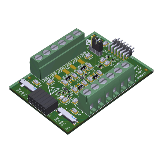
INA423X Evaluation Module
Description
The INA423X evaluation module (EVM) is a platform
to evaluate the main features and performance of the
INA4230 and INA4235. The EVM supports current
measurements up to 10A per channel and comes with
graphical user interface (GUI) support to read and
write to device registers.
Get Started
1. Buy the INA4230EVM or INA4235EVM evaluation
board.
2. Buy the
TI-SCB sensor control
SBOU298 – MARCH 2024
Submit Document Feedback
3. Download and install the
4. Read this user's guide to set up the hardware.
5. Run the INA423XEVM-GUI.
Features
•
•
•
•
board.
Copyright © 2024 Texas Instruments Incorporated
Drivers.
GUI support to read and write device registers as
well as view and save results data
EVM detached from SCB for custom use cases
Multiple channel support with single SCB/GUI
Conveniently powered from a common micro-USB
connector through the SCB
Description
PAMB Windows USB
INA423X Evaluation Module
1
Advertisement
Table of Contents

Related Manuals for Texas Instruments INA423X


Summary of Contents for Texas Instruments INA423X
- Page 1 3. Download and install the PAMB Windows USB Description Drivers. The INA423X evaluation module (EVM) is a platform 4. Read this user's guide to set up the hardware. to evaluate the main features and performance of the 5. Run the INA423XEVM-GUI.
-
Page 2: Kit Contents
Table 1-2. Device Summary DIGITAL MAX GAIN MAX OFFSET PRODUCT PROTOCOL RESOLUTION ERROR VOLTAGE INA4230 16-bit 0.75% ±75 µV INA4235 16-bit 0.1% ±10 µV INA423X Evaluation Module SBOU298 – MARCH 2024 Submit Document Feedback Copyright © 2024 Texas Instruments Incorporated... -
Page 3: Quick Start Setup
The GUI only supports one EVM and device type at a time; up to four EVMs total. Figure 2-2. Multiple EVMs Connected to SCB Controller SBOU298 – MARCH 2024 INA423X Evaluation Module Submit Document Feedback Copyright © 2024 Texas Instruments Incorporated... - Page 4 When measuring more than 10A, make sure the high current path does not go through the EVM (including the terminal blocks J1 or J5), as shown in Figure 2-3. Figure 2-3. IN+ and IN– Wiring for More Than 10A INA423X Evaluation Module SBOU298 – MARCH 2024 Submit Document Feedback Copyright © 2024 Texas Instruments Incorporated...
- Page 5 3. Connect the system ground to either of the GNDs on terminals J1 and J5. 4. Power on the system and observe the device states and outputs through the GUI. SBOU298 – MARCH 2024 INA423X Evaluation Module Submit Document Feedback Copyright © 2024 Texas Instruments Incorporated...
-
Page 6: Digital Circuitry
C8 is a bypass capacitor placed near the buffer to mitigate power supply noise and to help provide current quickly to the device when needed. INA423X Evaluation Module SBOU298 – MARCH 2024 Submit Document Feedback Copyright © 2024 Texas Instruments Incorporated... - Page 7 The new GUI and firmware can also be used with the SENS112 and PAMB Controller. If the firmware does not update automatically, then DFU mode can need to be entered manually. See Firmware Debug. SBOU298 – MARCH 2024 INA423X Evaluation Module Submit Document Feedback Copyright © 2024 Texas Instruments Incorporated...
- Page 8 If using the PAMB board instead, then these test points are placed near PK1 and PK2. With the MCU in DFU mode, the firmware can now be uploaded through the method outlined in Step INA423X Evaluation Module SBOU298 – MARCH 2024 Submit Document Feedback Copyright © 2024 Texas Instruments Incorporated...
- Page 9 Figure 3-3. TI Cloud Agent 4. To download the GUI for offline use, click the icon in the GUI Composer application and follow the prompts (see Figure 3-2). SBOU298 – MARCH 2024 INA423X Evaluation Module Submit Document Feedback Copyright © 2024 Texas Instruments Incorporated...
- Page 10 2. Connect the EVM to a different USB port. • Avoid using long cables and USB hubs. • If using a desktop PC, then try a USB port on the back. INA423X Evaluation Module SBOU298 – MARCH 2024 Submit Document Feedback Copyright © 2024 Texas Instruments Incorporated...
-
Page 11: Gui Operation
(Configuration) icon on the menu to the left. Figure shows an example of the configuration tool, which can change based on the device connected. Figure 3-8. Configuration Tool SBOU298 – MARCH 2024 INA423X Evaluation Module Submit Document Feedback Copyright © 2024 Texas Instruments Incorporated... - Page 12 – This shows the required sensing range to measure the Max Expected Current with the specified shunt resistor. – If a Max Expected Current is not specified, then the True Max Current field is used instead. INA423X Evaluation Module SBOU298 – MARCH 2024 Submit Document Feedback Copyright © 2024 Texas Instruments Incorporated...
- Page 13 For convenience, register settings can be saved and loaded back later to any device with the same register map. To do this, go to File > Register Data, as shown in Figure 3-10. Figure 3-10. Save and Load Register Settings SBOU298 – MARCH 2024 INA423X Evaluation Module Submit Document Feedback Copyright © 2024 Texas Instruments Incorporated...
- Page 14 – Changing the switch settings of any EVM sets that EVM as the selected EVM. • Collect and Plots settings: – Collect Data: INA423X Evaluation Module SBOU298 – MARCH 2024 Submit Document Feedback Copyright © 2024 Texas Instruments Incorporated...
- Page 15 COM port or the USB BULK channel, based on the mode. This is useful for interfacing the EVM with custom setups, scripts, or GUIs. SBOU298 – MARCH 2024 INA423X Evaluation Module Submit Document Feedback Copyright © 2024 Texas Instruments Incorporated...
- Page 16 – For this example, the EVM returns the results and state (idle or collecting) in JSON format: {"acknowledge":"wreg 0x20 0xf127"} {"console":"Writing 0xf127 to CONFIG1 register"} {"evm_state":"idle"} INA423X Evaluation Module SBOU298 – MARCH 2024 Submit Document Feedback Copyright © 2024 Texas Instruments Incorporated...
- Page 17 Stop collecting data format: stop – Where stop is always lower case. – The EVM returns the acknowledgment and state in JSON format: {"acknowledge":"stop"} {"evm_state":"idle"} SBOU298 – MARCH 2024 INA423X Evaluation Module Submit Document Feedback Copyright © 2024 Texas Instruments Incorporated...
- Page 18 +3V3 EN_IN SN74LVC1G07DRLR EN_IN +3V3 +3V3 +3V3 U2B 10V 0.1µF MNT_1 MNT_2 MNT_3 MNT_4 SN74LVC1G07DRLR CUS-14TB +3V3 TP19 EN_IN SH-J1 Figure 4-1. SENS112 Schematic INA423X Evaluation Module SBOU298 – MARCH 2024 Submit Document Feedback Copyright © 2024 Texas Instruments Incorporated...
- Page 19 These assemblies must comply with workmanship standards IPC-A-610 Class 2, unless otherwise speci e d. ¤ Assembly Note Trim the leads under J1 (back of PCB) to give clearance from surface Figure 4-2. SENS112 Hardware Schematic SBOU298 – MARCH 2024 INA423X Evaluation Module Submit Document Feedback Copyright © 2024 Texas Instruments Incorporated...
-
Page 20: Pcb Layout
PCB layers of the EVM. Figure 4-3. SENS112 Top View Figure 4-4. SENS112 Top Layer Figure 4-6. SENS112 Bottom Layer Figure 4-5. SENS112 Bottom View INA423X Evaluation Module SBOU298 – MARCH 2024 Submit Document Feedback Copyright © 2024 Texas Instruments Incorporated... - Page 21 Shunt, 2.54mm, Gold, Black Shunt, 2.54mm, Black 60900213421 Wurth Elektronik SW0, SW1 Slide Switch SP4T Surface Mount, Right Angle SMT_SW_11MM3_4MM1 CUS-14TB Nidec Copal Electronics SBOU298 – MARCH 2024 INA423X Evaluation Module Submit Document Feedback Copyright © 2024 Texas Instruments Incorporated...
- Page 22 FID3 R1, R9, R12, 10 mOhms ±0.5% 2W Chip Resistor 2512 (6432 Metric) Automotive AEC-Q200, 2512 PCS2512DR0100ET Ohmite Current Sense, Moisture Resistant Metal Film INA423X Evaluation Module SBOU298 – MARCH 2024 Submit Document Feedback Copyright © 2024 Texas Instruments Incorporated...
-
Page 23: Additional Information
Newer revisions are available from www.ti.com or the Texas Instruments' Literature Response Center at (800) 477-8924 or the Product Information Center at (972) 644-5580. When ordering, identify the document by both title and literature number. - Page 24 TI products. TI’s provision of these resources does not expand or otherwise alter TI’s applicable warranties or warranty disclaimers for TI products. TI objects to and rejects any additional or different terms you may have proposed. IMPORTANT NOTICE Mailing Address: Texas Instruments, Post Office Box 655303, Dallas, Texas 75265 Copyright © 2024, Texas Instruments Incorporated...
Need help?
Do you have a question about the INA423X and is the answer not in the manual?
Questions and answers