Advertisement
Advertisement
Table of Contents

Related Manuals for EnerSys NexSys+ Outdoor


Summary of Contents for EnerSys NexSys+ Outdoor
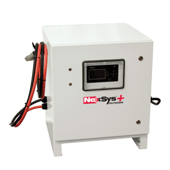
- Page 1 Charger OWNER’S MANUAL www.enersys.com...
-
Page 2: Table Of Contents
CONTENTS Features ..........4 Technical Information ...... 4 Safety Precautions ......7 Installation ........8 Operating Instructions ..... 9 Menu and Display Information ..12 Service and Troubleshooting ..16... - Page 3 For service, contact your sales representative or visit: https://www.enersys.com/en/sales-services/ Your Safety and the Safety of Others is Very Important You may be seriously injured if you don’t w WARNING follow these and other related instructions.
-
Page 4: Features
FEATURES & INFORMATION Features • Microprocessor-controlled. • Multi-voltage 24/48, 72/96V DC. • Able to auto-identify battery’s capacity. • HF modular technology with efficiency up • Able to adapt to State of Charge (SoC). to 94%. • Compatible with battery voltages of: •... - Page 5 TECHNICAL INFORMATION Technical Information (cont.) Output Power Letter Codes Output Power (kW) Number Modules Module Power (kW) 10.5 14.0 17.5 21.0 Cabinet Size (number of modules available) and DC Cable Size Module Phases Positions Standard Cable Gauge Comments Max 6 95 mm Six slot, max 21 kW cabinet.
- Page 6 TECHNICAL INFORMATION Technical Information (cont.) Profile Code Charger Profile Description NXFAST (*) For NexSys TPPL** 2V battery under fast, higher rate. Charge rate 0.251 to ® 0.40 C5. Properly FAST programmed Wi-iQ battery monitoring device ® (NexSys TPPL 2V battery). If not installed or no Comm, charger will use ®...
-
Page 7: Safety Precautions
• During charge, lead-acid batteries produce surface. hydrogen gas, which can explode if ignited. • For NexSys iON batteries, use only EnerSys ® ® Never smoke, use an open flame or create battery packs that include the battery sparks in the vicinity of the battery. -
Page 8: Installation
INSTALLATION Installation Location AC Circuit Protection For safe operation, choose a location which is free The user must provide suitable branch circuit of excess dust, combustible material, and corrosive protection and a disconnect method from the fumes. Also, avoid high temperatures (above 113°F AC power supply to the charger to allow for safe [45°C]) or potential liquid spill on the charger. - Page 9 INSTALLATION & OPERATION Installation (cont.) EU Declaration (S.I. 2016/588) EnerSys hereby declares that the chargers in the • Directive 2013/35/EU: ® NexSys + range are in conformity with the following Electromagnetic fields ® UK and European regulations: BS EN IEC 62311: 2020 •...
-
Page 10: Operating Instructions
• NexSys iON Li-ion batteries come with specific type ® of connector. The NexSys+ Outdoor charger comes Charger idle display with one or two connectors (LI Connector) depending on the charger model. When the charger is equipped with two connectors, both connectors must be connected, otherwise charge cycle will not start. - Page 11 OPERATING INSTRUCTIONS Operating Instructions (cont.) PAIRING with a Wi-iQ battery monitoring device: If one ® or more Wi-iQ battery monitoring device adapters are ® in range, the charger will turn on and apply current to the battery. The display will show “SCAN” followed by “IQLINK”.
-
Page 12: Menu And Display Information
OPERATING, MENU, & DISPLAY Operating Instructions (cont.) • Any other lit LED indicates a problem during Automatic Equalization Start charging. Please refer to paragraph Control Panel • If an equalization day has been programmed in for more information. charger configurations, the equalization charge will •... - Page 13 MENU & DISPLAY Logs Memorization Display Screen The charger can display the details of the last 300 charge cycles. The display here shows that 3 charges have been stored in memory. Memo 1 is the latest charge memorized. After memorizing the three-hundredth charge, the oldest record is deleted and replaced by the next oldest.
- Page 14 Password This menu provides access to the USB function to This is where the password is entered to gain update software. access to service level menus by authorized Software updates are provided by EnerSys EnerSys service personnel. ® ®...
-
Page 15: Service And Troubleshooting
SERVICE & TROUBLESHOOTING Fault Display In case of a fault, one of the corresponding fault codes listed below will appear on the display. If it is a critical fault, charging will stop and the red Fault LED will be illuminated. Fault Codes Fault Cause... - Page 16 SERVICE & TROUBLESHOOTING Fault Codes (cont.) Fault Cause Solution Check that the fan(s) is (are) working correctly and/or that the Module thermal fault (check the air flow, ambient, ambient temperature is not too high or whether there is poor MOD TH refer to Module Status Description to check the natural ventilation to the charger.
- Page 17 MAINTENANCE & SERVICE Maintenance and Service (cont.) Intervals for inspection are application-specific, depending on the environmental conditions in which the unit operates. The maximum interval for inspection is 90 days, with more frequent inspection required in areas with higher levels of airborne dust, dirt, or other particulate contaminants, or if the filter routinely becomes wet or moist.
- Page 18 NOTES...
- Page 19 NOTES...
- Page 20 © 2024 EnerSys. All rights reserved. Unauthorized distribution prohibited. Trademarks and logos are the property of EnerSys and its affiliates except CE and UK CA, which are not the property of EnerSys. Subject to revisions without prior notice. E.&O.E. EMEA-EN-OM-NEX-PLCH-OUTDOOR 0524...
Need help?
Do you have a question about the NexSys+ Outdoor and is the answer not in the manual?
Questions and answers