Advertisement
Quick Links
Advertisement

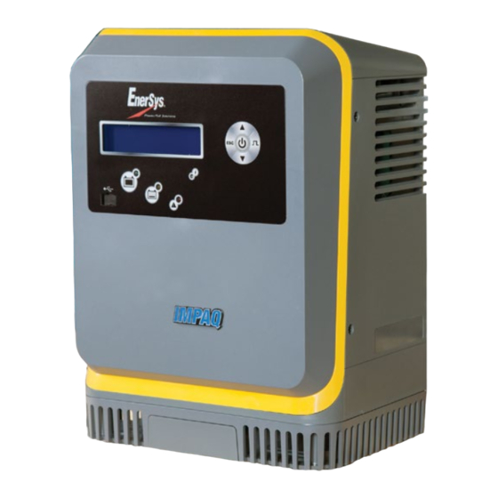
Summary of Contents for EnerSys IMPAQ EI1
- Page 1 Owner’s Manual CHARGING SOLUTIONS BATTERY CHARGERS MODEL: EI1/EI3 www.enersys.com...
- Page 2 Power Level Bottom DC Voltage Code Cabinet Size Input Voltage Code DC Voltage Code Charge Profile Part No. EI3-IN-6Y FOR SALES AND SERVICE CALL 800-ENERSYS Input Voltage Code Options 2866 BERNVILLE ROAD Charge Profile READING, PA 19605 750 AH Options WWW.ENERSYS.COM...
- Page 3 2.2.1. Operation: In Opportunity charging mode, the user can charge the battery during breaks, lunch, or any available time during the 3.13. For NexSys iON batteries, use only EnerSys battery packs that include ® ® work schedule. The Opportunity charge profile allows the battery...
- Page 4 4. Installation (cont.) 5. Operating Instructions 4.2. Cabinet mounting 5.1. Control panel features 4.2.1. The charger must be mounted on a wall, stand, shelf or floor in a vertical position. The minimum distance between two chargers must be 12 inches. 4.2.2.
- Page 5 5.7. Password This is where the password is entered to gain access to service level 5.3.2. Displaying a Charge Cycle menus by authorized EnerSys® service personnel. Proceed as follows: 5.8. Charging the Battery Select a record (MEMO x) using the buttons.
- Page 6 5. Operating Instructions (cont.) 7. Service and Troubleshooting (cont.) 7.1. Fault Display (cont.) 5.8.5. End of Charge without Equalization The green complete LED comes on after proper end of charge. Error Cause Solution The green complete LED is on and the display shows AVAIL. The Overdischarge Charge continues.
- Page 7 The frequency of this type of maintenance depends on the environment in which this unit is installed. For service, contact your sales representative or call:1-800-ENERSYS (USA) 1-800-363-7797 7.2.3. Any data, descriptions or specifications set forth herein are subject to change without notice. Before using the product(s), the user...
- Page 8 8. 1 kW Technical Specifications 1 kW Technical Specifications AC Input DC Output Charger Cable Part Number Voltage Max Amps Phase Min Cord AWG NEMA Plug Cells Max Current (A) EI1-AK-1A 120 4.7 1 16 5-15 6 1 35 10 AWG EI1-AK-2A ...
- Page 9 9. 3.5 kW Technical Specifications 3.5 kW Technical Specifications AC Input DC Output Charger Cable Part Number Voltage Max Amps Phase Min Cord AWG NEMA Plug Cells Max Current (A) EI3-GL-4G 208/220/240 7.4/7.0/6.4 3 14 L15-20 12/18/24 3.5 40/40/40 1/0 EI3-HL-4G ...
- Page 10 9. 3.5 kW Technical Specifications 3.5 kW Technical Specifications AC Input DC Output Charger Cable Part Number Voltage Max Amps Phase Min Cord AWG NEMA Plug Cells Max Current (A) EI3-GN-5G 208/220/240 7.7/7.3/6.7 3 14 L15-20 36/40 3.5 25/25 3/0 EI3-HN-5G ...
- Page 11 9. 3.5 kW Technical Specifications 3.5 kW Technical Specifications AC Input DC Output Charger Cable Part Number Voltage Max Amps Phase Min Cord AWG NEMA Plug Cells Max Current (A) EI3-IP-4Y 400 16.8 3 12 L16-30 12/18/24 10.5 210/195/180 3/0 EI3-JP-4Y ...
- Page 12 9. 3.5 kW Technical Specifications 3.5 kW Technical Specifications AC Input DC Output Charger Cable Part Number Voltage Max Amps Phase Min Cord AWG NEMA Plug Cells Max Current (A) 40/36 EI3GGR-5Y 400 9.6 3 14 L16-20 12/18/24 3.5 40/36 3/0 ...
- Page 13 8. 3.5 kW Technical Specifications 3.5 kW Technical Specifications AC Input DC Output Charger Cable Part Number Voltage Max Amps Phase Min Cord AWG NEMA Plug Cells Max Current (A) EI3-JP-4Y 480 19.2 3 10 L16-30 12/18/24 14 320/320/240 3/0 EI3-KP-4Y ...
- Page 14 8. 3.5 kW Technical Specifications 3.5 kW Technical Specifications AC Input DC Output Charger Cable Part Number Voltage Max Amps Phase Min Cord AWG NEMA Plug Cells Max Current (A) 40/36 EI3GGR-5Y 480 9.6 3 14 L16-20 12/18/24 3.5 40/36 3/0 ...
- Page 15 8. 3.5 kW Technical Specifications 3.5 kW Technical Specifications AC Input DC Output Charger Cable Part Number Voltage Max Amps Phase Min Cord AWG NEMA Plug Cells Max Current (A) 160/160/120 EI3HIR-4C 600 19 3 10 L17-30 12/18/24 10.5 240/240/180 3/0 ...
- Page 16 © 2023 EnerSys. All rights reserved. Trademarks and logos are the property of EnerSys and its affiliates except UL, which is not the property of EnerSys. Subject to revisions without prior notice. E.&O.E. AMER-EN-OM-IMP 1123...


Need help?
Do you have a question about the IMPAQ EI1 and is the answer not in the manual?
Questions and answers