
Related Manuals for Micsig SigOFIT


Summary of Contents for Micsig SigOFIT
- Page 1 SigOFIT Optical-fiber Isolated Probe Quick Guide Version updated: March 20, 2024 Shenzhen Micsig Technology Co., Ltd. www.micsig.com...
- Page 2 DO NOT block the heat dissipation port on the back of Optical-Electrical converter, otherwise the probe may be overheated and damaged. DO NOT excessively bend the fiber cable. Avoid tight radius (<8cm) bends, crushing, crimping, twisting, pulling or otherwise stressing the cable. SigOFIT™ Probe Quick Guide...
-
Page 3: Main Steps
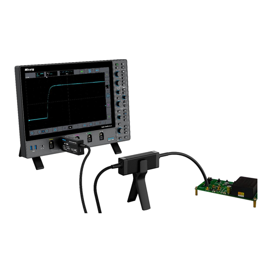
1. Connect the Optical-Electrical (O-E) converter to oscilloscope (Figure 1); O-E Converter Figure. 1 2. Set the oscilloscope input impedance to 50Ω, set corresponding attenuation ratio and delay time on the oscilloscope; Connect attenuating tip to the Electrical–Optical (E-O) converter (Figure 2); Figure. 2 SigOFIT™ Probe Quick Guide... - Page 4 4. Power the SigOFIT probe by connecting USB-C cable to O-E Converter using standard charger (localized); 5. Solder the MCX or MMCX adapter to the test board: 1) When testing Vgs signal, the signal pin (in the middle) of the adapter must be connected to the G-end of the MOSFET;...
-
Page 5: Button Descriptions
Quick Guide Over-voltage Warning: *When “Gain” button flashes and hearing a rapid "DiDiDiDi.." buzzer sound, indicate a over- voltage warning, please select a suitable attenuating tip. Over-heating Warning: *When hearing a “DiDi" sound every 2 seconds, it means the temperature of the Optical- Electrical (O-E) converter is overheated, please check whether the dissipation port is blocked. - Page 6 Adapters and coaxial lead Accessory name Withstand voltage range <300 Vpp MMCX-adapter <3000 Vpp MCX-adapter MMCX coaxial lead <300 Vpp <3000 Vpp MCX coaxial lead <8000 Vpp LCX coaxial lead * Please refer to User Manual or contact Micsig for more information.
Need help?
Do you have a question about the SigOFIT and is the answer not in the manual?
Questions and answers