Table of Contents
Advertisement
Quick Links
INSTRUCTIONS-PARTS LIST
This manual contains important
warnings and information.
READ AND KEEP FOR REFERENCE.
INSTRUCTIONS
240 VOLT
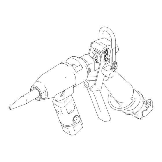
Hot Melt Gun
Model 243608 Bottom Feed
Model 243609 Bottom Feed with Trigger Switch
Model 243702 Top Feed
Model 243688 Top Feed with Trigger Switch
3500 psi (241 bar) Maximum Working Pressure
Table of Contents
. . . . . . . . . . . . . . . . . . . . . . . . . . . . . . . . . . . . . .
. . . . . . . . . . . . . . . . . . . . . . . . . . . . . . . . . . . . . . .
. . . . . . . . . . . . . . . . . . . . . . . . . . . . . . . . . . . . .
. . . . . . . . . . . . . . . . . . . . . . . . . . . . . . . . . . . . .
. . . . . . . . . . . . . . . . . . . . . . . . . . . . . . . .
. . . . . . . . . . . . . . . . . . . . . . . . . . . . . . . . . . . . . .
. . . . . . . . . . . . . . . . . . . . . . . . . . . . . . . . . . . . . . . .
. . . . . . . . . . . . . . . . . . . . . . . . . . . . . . . .
. . . . . . . . . . . . . . . . . . . . . . . . . . . . .
. . . . . . . . . . . . . . . . . . . . . . . . . .
GRACO INC. P.O. BOX 1441 MINNEAPOLIS, MN 55440-1441
2
2
5
6
9
10
14
18
19
. . . . . . . . .
20
20
ECOPYRIGHT 2000, GRACO INC.
Graco Inc. is registered to I.S. EN ISO 9001
309161
Rev. A
TI0371
TI0371
Advertisement
Table of Contents

Related Manuals for Graco 243608


Summary of Contents for Graco 243608
-
Page 1: Table Of Contents
......GRACO INC. P.O. BOX 1441 MINNEAPOLIS, MN 55440–1441 ECOPYRIGHT 2000, GRACO INC. Graco Inc. is registered to I.S. EN ISO 9001... -
Page 2: Symbols
Symbols Warning Symbol Caution Symbol WARNING CAUTION This symbol alerts you to the possibility of serious This symbol alerts you to the possibility of damage to injury or death if you do not follow the instructions. or destruction of equipment if you do not follow the instructions. - Page 3 D This equipment is for professional use only. D Read all the instruction manuals, tags, and labels before operating the equipment. D Use the equipment only for its intended purpose. If you are uncertain about usage, call your Graco distributor.
- Page 4 Notes 4 309161...
-
Page 5: Installation
Installation Install the gun as follows: Ground the System D connect material hose D connect the electrical cable WARNING D make sure the gun is grounded FIRE AND EXPLOSION HAZARD Connect the Material Hose to the Gun To reduce the risk of a fire, explosion, and serious injury, proper electrical Securely connect the material hose to the gun material grounding of every part of your system is... -
Page 6: Operation
Operation Pressure Relief Procedure Gun Trigger Safety WARNING WARNING INJECTION HAZARD INJECTION HAZARD To prevent accidental triggering of the The system pressure must be manually gun and reduce the risk of a serious relieved to prevent the system from injury, including fluid injection or splash- starting or dispensing accidentally. - Page 7 Operation Dispensing Flushing Safety 1. Start the fluid supply pump. WARNING 2. The fluid flow rate is controlled at the pump. Adjust FIRE AND EXPLOSION HAZARD the pump pressure to obtain the desired flow rate. To reduce the risk of a fire, explosion, or It is recommended that you use the lowest pres- serious injury, sure necessary to dispense the fluid.
- Page 8 Notes 8 309161...
-
Page 9: Troubleshooting
Troubleshooting Some solutions require disassembling the gun. Always relieve system pressure before performing these proce- dures. WARNING To reduce the risk of serious injury whenever you are instructed to relieve pressure, always follow the Pressure Relief Procedure on page 6 . See PARTS section (pages 14-17) for the parts that need to be serviced. -
Page 10: Service
(19) as instructed on page 13. damaged. Reassemble the gun or return it to your nearest Graco distributor. Do not use the gun until the problem is corrected. 2. Follow the torque, sealant and lubrication notes for your gun model number. - Page 11 Service Install new heater unit or sensor 1. Install the shrink wrap over the leads. 2. For Therm–O–Flow Plus 8 pin assemblies, remov- al and replacement of the heaters and RTD require a pin extraction tool, new connector pins, and a pin GUN SWITCH crimping tool.
- Page 12 Service Inspection Frequency Adjusting the Needle Assembly The trigger travel and corresponding valve opening are Automatic Dispense Valve factory set. To adjust this setting, follow the procedure below. Inspect automatic dispense valve at least once every two weeks for leakage or other visible damage. WARNING Check specifically for: INJECTION HAZARD...
- Page 13 Service Adjusting the Spring Tension Valve Stem and Seal Service If fluid leaks past seal (16c), the seal or needle (16a) WARNING may be worn or damaged. To replace the seal or valve stem, follow the procedure below. INJECTION HAZARD WARNING To reduce the risk of a serious injury, including fluid injection, follow the Pres-...
-
Page 14: Parts
Parts Models 243608 and 243609 Hot Melt Gun Model 243609 only 16d 16e 16b 16c Model 243608 only See Detail A Detail A Orient snap rings as shown. NOTE: Apply heat transfer compound to For ease of assembly, install pins and cylindrical surface of heater (27). - Page 15 CONNECTOR, male, crimp C57733 SWIVEL, 3/8 npt(f) X 3/8 npt(f) (Model 243608) C32368 RING (Model 243609) C27051 TRIGGER C19977 SCREW, cap (Model 243608) C32004 HANGER, gun (Model 243609) C20442 RING, retaining, ext. 157021 WASHER, lock, internal C27035 PIN, trigger 108483...
- Page 16 Parts Models 243688 and 243702 Hot Melt Gun Model 243688 only Model 243702 only 3 Ref. See Detail A Detail A NOTE: Orient snap rings as shown. Apply heat transfer compound to For ease of assembly, install pins and cylindrical surface of heater (27). snap rings from top to bottom.
- Page 17 Parts Model 243688 Trigger Switch Hot Melt Gun (Includes items 1 – 51) Model 243702 Manual Hot Melt Gun (Includes items 1 – 51) Ref. Ref. Part No. Description Qty. Part No. Description Qty. C27014 ADAPTER 196507 BODY, gun, flow C32003 NOZZLE C32028...
-
Page 18: Technical Data
......3/8 npt(f) Weight 243608 and 243609 ... . 3.5 lbs. (1.6 kg) -
Page 19: Change Summary
Manual Change Summary Changed cover page from Rev. – to Rev. A for release. 309161 19... -
Page 20: Graco Warranty And Limitation Of Liability
Graco distributor to the original purchaser for use. With the exception of any special, extended, or limited warranty published by Graco, Graco will, for a period of twelve months from the date of sale, repair or replace any part of the equipment determined by Graco to be defective.
Need help?
Do you have a question about the 243608 and is the answer not in the manual?
Questions and answers