
Related Manuals for Growatt Hope 5.0L-B1


Summary of Contents for Growatt Hope 5.0L-B1
- Page 1 Residential Energy Storage Hope 5.0L - B1 Battery System Version:1.0 044.SK0014000...
- Page 2 This document describes the installation, electrical connection, operation, commission, maintenance and troubleshooting of Hope 5.0L-B1 Battery System (hereafter simply put Hope 5.0L). Before installing and operating Hope 5.0L-B1, ensure that you are familiar with product features, functions, and safety precautions provided in this document.
-
Page 3: Table Of Contents
Table of Contents 1.Product Overview ································································································1 1.1 Product Description ····························································································· 1 1.2 Appearance ·······································································································1 1.2.1 Dimension (unit:mm) ························································································ 1 1.2.2 Introduction to the battery operation panel ···························································· 2 1.3 Function and Introduction ·····················································································4 1.4 Battery software upgrade ····················································································· 4 1.4.1 Upgrade via USB ······························································································ 4 1.4.2 Upgrade via Inverter ·························································································... -
Page 4: Product Overview
1.Product Overview 1.1 Product Description Hope 5.0L-B1 consists of 100Ah cells which form 51.2V voltage battery module and 16 cells in serial connection (1P16S). Max parallel number is 48pcs which can expand the capacity to up to 240KWH. For meeting the needs of home storage power supply, batteries and inverters are combined to be home storage solar system with protection functions such as overcharge, over-discharge, overcurrent, overtemperature, and short circuit. -
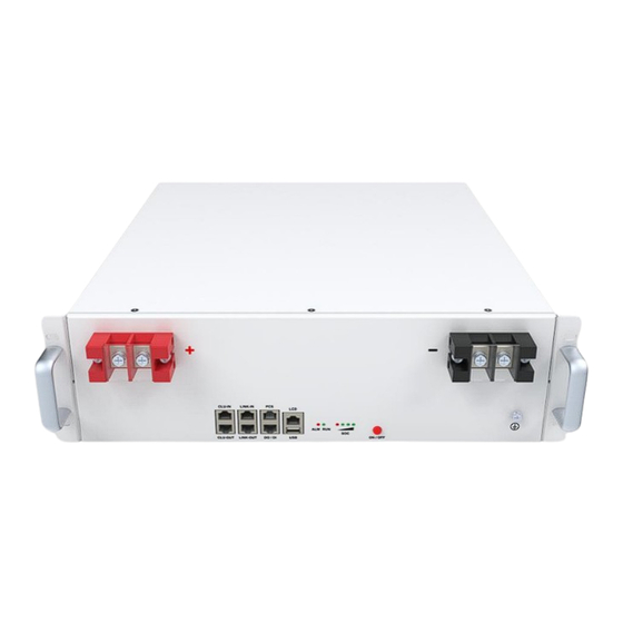
Page 5: Introduction To The Battery Operation Panel
1.2.2 Introduction to the battery operation panel Figure 2: Introduction to the battery operation panel Location Port Function Keys for battery on and off ON/OFF Displaying battery SOC status Displaying running status RUN/ALM USB interface for system upgrade, a mobile phone can’t be charged For linking external integration LCD Relay output/input... - Page 6 Figure3: LED light Name Color Description ON/OFF Power on/off Button LED 4 Green 80%-100% LED 3 Green 60%-79% LED 2 40%-59% Green LED 1 0%-39% Green Normal Running Fault or protection status...
-
Page 7: Function And Introduction
1.3 Function and Introduction Function Description APP Display Display BMS information and upgrade and Upgrade 2 Circuits, with isolation, One for battery parallel communication, the CAN communication other for communication with inverter Battery in Parallel Max parallel number is 48pcs SOC Algorithm Dynamic SOC estimation for battery packs Based on different temperature, The evaluation capacity of voltage and... -
Page 8: Upgrade Via Inverter
1.4.2 Upgrade via Inverter Connect to WiFi monitor for remote upgrade through inverter. l ight that displays the SOC continuously flashes once per 500ms during the upgrade The LED process. The host will upgrade the slave machine in turn after the upgrade is completed. During upgrading, LED lights of SOC flash once every 500ms, and become normally after the upgrade. -
Page 9: Safety Precautions
2.2 Safety Precautions 2.2.1 Environment requirements Do not expose the battery to temperature above 55℃ ,or heat sources. Do not install or use the battery in wet locations, moisture , corrosive gases or liquids, such as bathroom. Do not expose the battery to direct sunlight for extended periods of time. ... - Page 10 Electric shock hazard Explosive gas May leak corrosive electrolyte Heavy enough to cause severe injury Keep the Pack away from children Make sure the battery polarity well connected Do not expose to fire Operate according to Manual Figure4:Nameplate...
-
Page 11: Emergency Responses
2.4 Emergency Responses Manufacturer takes foreseeable risk scenarios into consideration and is designed to reduce hazards and dangers. However, if the following situation occurs, do as below: Situation Treatment Solution Occurs 1. Avoid touch of leaking liquid or gas. If you touch the leaking electrolyte, do as below immediately. -
Page 12: Transportation Requirement
If the battery has not been used for more than six months, it needs to be charged, the charging procedure is as follows: 1) Identify the PACK that needs charging. 2) Refer to quick installation guidance, complete the installation and wire connection. Ensure BATTERY in off status during all the steps. -
Page 13: Installation
4 Installation Ensure to read the Guidance before installation in order to understand product information and safety cautions. Operators should be well trained technicians and fully understand the whole photovoltaic system, grid network, working principle and national regional standards. Installers must use insulating tools and wear safety equipment. Device damages caused by failure to comply with storage, transportation, installation and use requirements specified in Guidance are not covered by Warranty. -
Page 14: Installation Required Tools
4.2 Installation Required Tools The following tools are required to install the pack: Screw Driver 5mm Allen key Wrench Multi-meter Tap Measure It is recommended to wear the following safety gear when dealing with the pack. Insulated Glove Safety Goggle Safety Shoes 4.3 Check 4.3.1 Pre-installation Check... -
Page 15: Check Packing List
4.3.2 Check Packing List... -
Page 16: Installation
4.4 Installation 4.4.1 Battery Placement Please install indoors and ensure the level of the ground. The maximum quantity of stacking battery pack is 6, only support to horizontally mounted. Make sure the batteries are mounted in the correct orientation. Please refer to the picture below (√... -
Page 17: Single Battery Installation
4.4.3 Single Battery Installation Make sure the battery is in off mode and the battery breaker is off Ensure there are no tangled cables after battery wiring. Step 1 : Fix the ground wire to the ground terminal with an M4 screw, and fix the other end to the inverter. -
Page 18: Battery Capacity Expansion Installation
When connecting the power cable, make sure the direction of OT terminal is correct. Don’t stack two OT terminals on one power port. Figure 6:Single Battery Installation Diagram 1) The battery is not allowed to be wired in the running state, and the battery should all be off before installation. -
Page 19: Battery Pack Power Expansion Installation
Connect the ground terminal of each battery to the ground strip. Step 3 Connect Power Cable Connect the +/- terminals of each battery to the +/- terminals of the next battery, and then connect the wires to the inverter. Figure 7:Capacity Expansion Installation Diagram 1) The battery is not allowed to be wired in the running state, and the battery should all be off before installation. - Page 20 Max Output Power Expansion parallel is 10pcs to creat a 50kw expanded energy storage system Step 1:Connect Network Cable 1. Insert one end of the network cable A into the inverter interface of battery 1 and the other end into the BMS network port of the inverter. 2.
-
Page 21: Battery Pack Capacity And Power Expansion Installation
3) Please install the communication line first, then protect the unused ports and USB ports against dust, and finally install the power cable. 4) We recommend installing a circuit breaker between the inverter and the battery. For the specifications of the circuit breaker, we recommend using a molded case circuit breaker with a rated operating voltage higher than 80Vdc, the rated working current is determined by the power. - Page 22 Figure 9:Installation Diagram for Capacity Expansion 1) The battery is not allowed to be wired in the running state, and the battery should all be off before installation. 2) Refer to Figure 9 for power cable wiring. 3) Please install the communication line first, then protect the unused ports and USB ports against dust, and finally install the power cable.
-
Page 23: Stackable Installation With Bracket Support
4.4.7 Stackable Installation with Bracket Support Check and confirm the battery is powered off and battery breakers are turned off before any process. Step1: prepare support brackets Step2:set battery into 2pcs of brackets from the rear. Step3: stack battery packs with brackets and fasten screws. Max 6 pcs battery packs can be stacked in this way. -
Page 24: Power On/Off
5 Power on/off The installation and use of batteries involve much specialized knowledge. Therefore, technicians should be given appropriate technical training and obtain operational certificates in compliance with local laws and regulations. Please ensure technicians have obtained training certificate before operation. Please stand on dry insulating objects and do not wear conductive material such as watches and necklace during operation. -
Page 25: Maintenance Guide
6 Maintenance Guide 6.1 Preparation Tools like safety gloves, cross head driver and socket wrench should be prepared. Turn off and turn on new PACK 1. If the PACK is power-off. Press power button for 1 second to turn on. 2. - Page 26 1.there is no safety risk, but user should stop using. 2. Check whether Failed communication between External communication inverter and battery is normal. communication for battery and 3. if battery and inverter failure inverter communication failed, but ensure communication wire connection well,please contact installer for repairing battery.
-
Page 27: Technical Specifications
7 Technical Specifications Functional parameters of Hope 5.0L-B1 are as below: Items Specification Battery Module Hope 5.0L-B1 Rated Capacity/Energy 100Ah/5.12kWh Nominal Voltage 51.2V Operating voltage 40 – 58.4V Max.charging current(25℃) 100A Max.discharging current(25℃) 100A Max peak current 250A 150ms Battery Type... - Page 28 Appendix 1 SOC indicator Status Items LED1 LED2 LED3 LED4 (t=500ms) (t=500ms) (t=500ms) (t=500ms) 1%-19% (t=500ms) (t=500ms) (t=500ms) (t=500ms) (t=500ms) (t=500ms) (t=500ms) 20%- Charge (t=500ms) (t=500ms) 40%- (t=500ms) 60%- 80%- 100% 100%- 79%- Discharg 59%- e SOC 39%- 19%-1% (t=500ms) 100%- 79%- 59%-...
- Page 29 LED indicator 2 Status Item Open ciruit Charge & ( t=1s) discharge MOS Closed circuit Battery under voltage (t=1s) Battery over voltage (t=1s) Cell under voltage (t=1s) Cell over voltage (t=1s) Alarm before shut off (t=1s) Charge over current (t=1s) Discharge over current (t=1s) grade1...
- Page 30 High ambient (t=1s) temperature Communication (t=1s) between clusters failed MCU short circuit (t=1s) FET short circuit (t=1s) Too many parallel (t=1s) machines Battery under voltage Battery over voltage Cell under voltage Cell over voltage Short circuit Charge over current Discharge Over current 1 grade Parallel versions are inconsistent...
- Page 31 Same Address Failure Pre-charge Timeout Pre-charge short circuit AFE disconnected Cell sampling cable disconnected Temperature sampling cable disconnected Abnormal Battery Voltage Sampling Temperature Short Circuit Abnormal Load Voltage Sampling Failed to load parameters AFE over voltage AFE under voltage AFE charging over current AFE discharging over current...
- Page 32 Excessive differential temperature High ambient temperature Inconsistent versions between clusters Duplicate failures between clusters FET Over charge temperature FET Low charge temperature FET Over discharge temperature FET Low discharge temperature Note : Indicates always on t=500ms indicates the flashing interval 500ms t=1s indicates the flashing interval 1s...
- Page 33 Appendix 2...
Need help?
Do you have a question about the Hope 5.0L-B1 and is the answer not in the manual?
Questions and answers