Table of Contents
Advertisement
Advertisement
Table of Contents
Troubleshooting

Related Manuals for Growatt APX 5.0P-S0-US


Summary of Contents for Growatt APX 5.0P-S0-US
- Page 1 APX 5.0~30.0P-S0-US High Voltage Battery System User Manual...
- Page 2 About this Document This document introduces the APX 5.0~30.0P-S0-US Battery System (short for APX) in terms of installation, electrical connection, operation, commission, maintenance, and troubleshooting. Before installing and operating the APX system, ensure that you are familiar with product features, functions, and safety precautions provided in this document.
-
Page 3: Table Of Contents
Table of Contents Product Overview .................. 1 1.1 Intended Use ......................... 1 1.2 Appearance ........................1 1.2.1 APX 55042-P0-US (Power Module) ................ 1 1.2.2 APX 5.0P-B1-US (Battery Module) ................. 4 1.3 Working Principle and Function................5 2 Safety ....................... 6 2.1 General Safety ...................... -
Page 4: Product Overview
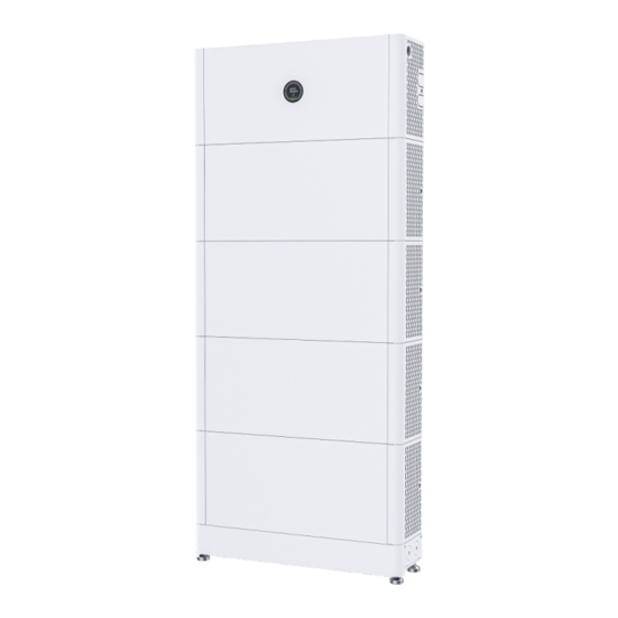
1 Product Overview 1.1 Intended Use The entire APX 5.0~30.0P-S0-US high-voltage energy storage system is composed of a APX 55042-P0-US (hereinafter referred to as Power Module) and multiple APX 5.0P-B1-US battery modules (hereinafter referred to as Battery Module, the maximum number of Battery Module connected in parallel is 6). - Page 5 Port Function Turn on/off the power connection from Power DC switch Module to hybrid Inverter Hole to route through the cables connected to BAT+ and BAT- Hole to route through the parallel communication LINK cable Pressure relief valve Provide protection against excessive pressure Ground terminal, connect to the hybrid inverter Link-out APX system parallel communication output port...
- Page 6 LED display Figure1- 3: LED display Function Function description Display SOC Display current SOC in a progress circle. Eight light bars rotate clockwise when the Display upgrade status program is updating. When charging, light bars light up one by Charging one clockwise.
-
Page 7: Apx 5.0P-B1-Us (Battery Module)
1.2.2 APX 5.0P-B1-US (Battery Module) Battery Module consists of LFP battery cells, a DC-DC converter, mechanical parts, the battery management unit (BMU) as well as power and communication terminals. Product appearance is shown below. Figure 1-5: Side views of the Battery Module Location Port Function... -
Page 8: Working Principle And Function
Dimensions (unit: mm) 690 mm(27.17 in) 185 mm(7.28 in) Figure 1-6: Dimensions of APX 5.0P-B1-US 1.3 Working Principle and Function The APX 5.0~30.0P-S0-US high voltage battery system is composed of a Power Module APX 55042-P0-US and multiple Battery Modules APX 5.0P-B1-US connected in parallel. It contains electrochemical batteries, battery control units, power control units, battery management units, power and signal terminals, and mechanical parts. -
Page 9: Safety 2
The battery system has been designed and tested in accordance with strict rules to meet international safety certification requirements. Before installing or using the battery system, please read all safety instructions carefully and observe the rules. Growatt will not be liable for any consequence of the following circumstances: Damage during the transportation by the customer. -
Page 10: Operation Precautions
2.2.2 Operation Precautions Do not touch the battery system with wet hands. Ø Do not disassemble the battery system without authorization. Ø Do not crush, drop or pierce the battery pack and the high voltage controller. Ø Dispose of the batteries according to local safety regulations. Ø... - Page 11 APX High Voltage Battery System APX 5.0P-S0-US/ □ □ 400Vdc/2.5kW/ 5kWh/4.5kWh APX 10.0P-S0-US/ □ 400Vdc/5kW/ 10kWh/9kWh System Model/ APX 15.0P-S0-US/ □ Nominal Voltage/ 400Vdc/7.5kW/ 15kWh/13.5kWh Nominal Power/ APX 20.0P-S0-US/ Nominal Energy/ □ 400Vdc/10kW/ Rated Energy/ 20kWh/18kWh APX 25.0P-S0-US/ □ 400Vdc/12kW/ 25kWh/22.5kWh...
-
Page 12: Emergency Responses
If the battery system is soaked or submerged in water, do not touch Flood emergency the batteries to avoid electric shock. Contact Growatt or your distributor immediately for technical assistance. The shell damage requires extra attention as it is of high risk. Do not Shell damage use batteries with a damaged shell, which may cause safety hazards. -
Page 13: Storage And Transportation 3
Storage and Transportation 3 3.1 Storage Requirements Ø Place the batteries according to the signs on the packing case. Do not put batteries upside down or on their side. Ø Do not store damaged batteries near undamaged ones. Ø The storage environment requirements are as follows: Ø... -
Page 14: Installation
4 Installation Read through the Guidance before installation to understand product Ø information and safety precautions. Only qualified and well-trained technicians who fully understand the Ø whole photovoltaic system, grid network, battery system, working principle and national/local standards are allowed to perform operations on the battery. -
Page 15: Installation Tools
4.2 Installation Tools Prepare the following tools to install the battery system: M6 2Nm(17.6inlbs) M4 2Nm(17.6inlbs) M8 2Nm(17.6inlbs) M3 1Nm(8.8inlbs) Socket Wrench Hammer Drill Screwdriver Measuring Tape Marker Multimeter It is recommended to wear the personal protective equipment when operating the battery system. - Page 16 Battery system capacity System configurations (floor-mounted installation) 5 kWh 10 kWh A+B*2 15 kWh A+B*3 20 kWh A+B*4 25 kWh A+B*5+C 30 kWh A+B*6+C 4.3.1.2 Check the package of the APX 55042-P0-US Bottom battery connecting piece*2 M8 expansion screw*2 APX 55042-P0-US APX 5.0P-B1-US Base (Power Module) Output power cable...
-
Page 17: Floor-Mounted Installation
4.3.1.3 Check the package of the APX 5.0P-B1-US to Battery Module APX 5.0P-B1-US Parallel cable 1 (Battery Module) Anti-tipping plate * 2 ST 63×40 Self-tapping screws * 2 M4x9 stainless steel screw * 4 Mounting bracket * 1 Trim-cover*2 Connecting piece for mounting brackets * 2 Figure 4-4: Packing list of the APX 5.0P-B1-US Ensure that you have the standard accessories - the Power Module Ø... - Page 18 Secure the base 90° Deep 45~50mm M8 expansion Dia 10.0mm (Deep1.77~1.97in) (Dia 0.3in) screw 1 Ensure that the alignment markings are properly marked. Secure the base to the ground using the M8 expansion screws Move up the bottom battery connecting piece. Figure 4-6: Secure the base Step 1: Place the base on the predetermined installation position to mark the hole positions, then drill holes with the appropriate drill bit.
- Page 19 Install the battery module Fix the L-shaped anti-tip kit to the BM on both sides. Fix the L-shaped anti-tip kit to the mounting bracket on both sides. Secure the captive screws on the bottom battery connecting piece to the BM. Move up the handle.
-
Page 20: Electrical Connection
4.4 Electrical Connection Do not forget to wear ESD wrist strap and gloves, safety shoes and goggles. WARNING 4.4.1 Connecting to the inverter Note: Please be careful with the components inside the inverter during drilling. drilling MIN 3- 11.4K TL- XH-US START BAT+ BAT -... -
Page 21: System Connection
4.4.2 System connection A DC switch (switch-disconnector) has been installed in the Power Ø Module. Therefore, a DC circuit breaker is not recommended to be installed between the battery system and the hybrid inverter system. If you have installed a DC circuit breaker, do not perform operations on the DC circuit breaker with power-on, otherwise the machine may be damaged. - Page 22 Fig 4-13 Note: When installing in two columns, please purchase the APX-US parallel extension package, which includes power cables, communication cables, ground cables and a base. 4.4.2.2 System connection diagram Temperature 90℃(19 4℉) Screw 2Nm (17.6inlbs) BAT+ BAT- 2Nm(17.6inlbs) 1Nm(8.8inlbs) 2Nm(17.6inlbs) Insert the plug Insert the plug...
- Page 23 Note: Battery modules must be paralleled with B+ to B+, B- to B-. Link-in BAT+ BAT- Insert the plug Insert the plug APX 5.0P-B1-US Parallel Cable...
- Page 25 Trim-cover lid Trim-cover lid Figure 4-15: Two-column installation Note: The battery is not allowed to be installed when the machine is running. Ensure that all the lights indicating “RUN” of battery modules are off before installation. Ensure that the PE cable is securely connected.
- Page 26 4.4.2.3 Electrical wiring connection A. APX 55042-P0-US (Power Module) wiring Figure 4-16: APX 55042-P0-US wiring diagram Step 1: Insert the power cable into the corresponding port. The click sound indicates a robust connection. The power cables are delivered with the Power Module. Step 2: Insert the communication cable into the "INV "...
- Page 27 B. APX 5.0P-B1-US (Battery module) wiring Figure 4-17: APX 5.0P-B1-US wiring diagram Step 1: Insert the power cable into the corresponding port. The click sound indicates a robust connection. Step 2: Insert the communication cables into the “Link-in” and “Link out” port, and then tighten the communication terminals clockwise.
- Page 28 BAT+ BAT - APX55042-P0-US Right trim-cover 2Nm(17.6inlbs) 2Nm(17.6inlbs) Figure 4-18: Installing external cables...
-
Page 29: Power On/Off The Apx Battery System
Power on/off the APX Battery 5 System Personnel who install and operate the Battery System must receive Ø thorough training and possess the local national required qualifications before operation. Only qualified professionals and trained personnel are allowed to install, operate and maintain the equipment. Please stand on dry insulating objects and do not wear conductive Ø... - Page 30 The APX battery system will automatically shut down in a few minutes after the LED indicator and the logo “Growatt” go off. Do not turn on the switch until it is completely powered off.
-
Page 31: Power Off The Apx Battery System
1. Turn off the DC switch on the APX, disconnect the AC circuit breaker and the PV switch of the inverter. 2. Wait for 15 minutes until the LOGO indicator (GROWATT) on the APX turns off, indicating that the system is completely powered off. -
Page 32: Maintenance Guide
6 Maintenance Guide 6.1 Preparation After the system is powered off, the remaining electricity and heat still exist in the chassis, which may cause electric shocks or burns. Therefore, you need to wear protective gloves and perform operations 10 minutes after the system is powered off. 6.2 Replace a fuse Figure 6-1: Replace a fuse Step 1: Power off the APX system. -
Page 33: Led Indicators
The Battery Module contains batteries. Dispose of them in compliance Ø with local laws and regulations. After the system is powered off, beware the residual heat of the heat Ø sink to avoid burns. NOTICE 6.4 LED indicators Figure 6-2: LED indicators If the LED indicators are not displayed, you can knock the enclosure below the display Ø... -
Page 34: Troubleshooting
6.5 Troubleshooting Indicator Description Cause Measures 1.There is no safety risk. 2.Ensure that the inverter is Communication powered on. To PCS loss between 3.Check if the PCS and battery Communication PCS and the communication terminals are failure APX battery well connected. system 4.If the problem persists , users should contact the installer to... - Page 35 Indicator Description Cause Measures The power Check whether the power cable cable is Power cable between the Power Module and disconnected disconnected the Battery Module is securely from the Power connected. Module The external 1.Check whether the External communication communication cable is securely communication cable is not connected.
-
Page 36: System Fault Information List And Troubleshooting Suggestions
BM to PM open- FAULT 407(0) between BM and PM, then restart the machine. If the circuited problem persists, please contact Growatt support. Power off the machine and wait for 30 minutes FAULT 408(0) Over-Temp before you restart the machine. If the problem persists, please contact Growatt support. - Page 37 Growatt support. When the temperature of the machine is close to - 40°C (-40°F), it will raise this alarm. If the Temperature sensor FAULT 700(0) temperature is higher than -40°C(-40°F) when this open-circuited alarm is reported, please contact Growatt support.
- Page 38 Description Suggested measures Reduce the load power, then restart the machine. FAULT 707(0) Overload fault If the problem persists, please contact Growatt support. Reduce the load power, then restart the machine. FAULT 707(2) Overload fault If the problem persists, please contact Growatt support.
- Page 39 If the problem persists, please contact Growatt support. Reduce the load power, then restart the machine. Discharge Overload WARN 707(1) If the problem persists, please contact Growatt Alarm support. Reduce the load power, then restart the machine. Discharge Overload...
- Page 40 Power off the machine and wait for 30 minutes FAULT 408(0) Over-Temp before you restart the machine. If the problem persists, please contact Growatt support. Power off the machine and check the power BM transient FAULT 409(2) cables, then restart the machine. If the problem overvoltage persists, please contact Growatt support.
- Page 41 40°C (-40°F), it will raise this alarm. If the FAULT 700(0) open-circuited temperature is higher than -40°C(-40°F) when this alarm is reported, please contact Growatt support. Reduce the load power, then restart the machine. FAULT 707(0) Discharge Overload If the problem persists, please contact Growatt support.
-
Page 42: Cleaning
Power off the machine and check the power cables, then restart the machine. If the WARN 704(0) BM overvoltage problem persists, please contact Growatt support. Power off the machine and check the power cables, then restart the machine. If the... -
Page 43: Technical Specifications 7
Technical Specifications 7 APX 55042-P0-US (Power Module) Items Specifications Model APX 55042-P0-US B+/B- voltage range 330V-450V BAT+/BAT- voltage range 380V-550V Maximum current Peak current Temperature range -10℃~+50℃(+14°F~+122°F) IP rating IP66 Warranty 10 years Communication method CAN2.0 690*185*295 mm ±2mm Dimensions (W/D/H) (27.17*7.28*11.61 in±0.08 in) Weight 16±1kg(35.27±2.20 lbs) - Page 44 Formula for calculating the rated capacity: Rated capacity of the measured module: 100 Ah N (Number of modules connected in Parallel): 1~6 Rated capacity (Ah) = 100 Ah *N Growatt USA,Inc. 9227 Reseda Blvd, #435 Northridge, CA 91324, USA. +1-866-686 0298 usaservice@ginverter.com...
- Page 45 Download Manual Growatt USA,Inc. 9227 Reseda Blvd, #435 Northridge, CA 91324, USA. +1-866-686 0298 usaservice@ginverter.com us.growatt.com GR-UM-340-A-00...
Need help?
Do you have a question about the APX 5.0P-S0-US and is the answer not in the manual?
Questions and answers