Table of Contents
Advertisement
Quick Links
OPERATING INSTRUCTIONS AND SPECIFICATIONS
CompactRIO NI cRIO-9012/9014
Intelligent Real-Time Embedded Controller for CompactRIO
™
8
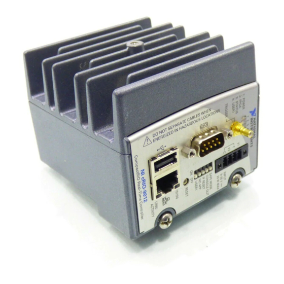
1 LEDs
2 SMB Connector
3 Power Connector
4 DIP Switches
Figure 1. CompactRIO cRIO-9012/9014
1
2
7
5 Reset Button
6 RJ-45 Ethernet Port
7 USB Port
8 RS-232 Serial Port
3
4
5
6
Advertisement
Table of Contents

Related Manuals for National Instruments CompactRIO NI cRIO-9012


Summary of Contents for National Instruments CompactRIO NI cRIO-9012
- Page 1 OPERATING INSTRUCTIONS AND SPECIFICATIONS CompactRIO NI cRIO-9012/9014 ™ Intelligent Real-Time Embedded Controller for CompactRIO 1 LEDs 5 Reset Button 2 SMB Connector 6 RJ-45 Ethernet Port 3 Power Connector 7 USB Port 4 DIP Switches 8 RS-232 Serial Port Figure 1. CompactRIO cRIO-9012/9014...
-
Page 2: Safety Guidelines For Hazardous Locations
This document describes how to connect the NI cRIO-9012/9014 real-time embedded controllers to networks and how to use the features of the controllers. This document also contains specifications for the controllers. Safety Guidelines Operate the cRIO-9012/9014 only as described in these operating instructions. - Page 3 Complete the following steps to install the controller on the chassis. Make sure that no power is connected to the controller or the chassis. Align the controller with the chassis as shown in Figure 3. © National Instruments Corporation cRIO-9012/9014 Operating Instructions and Specifications...
- Page 4 1 Controller 3 Controller Slot 2 Captive Screws 4 Reconfigurable Embedded Chassis Figure 3. Installing the Controller on the Chassis (Eight-Slot Chassis Shown) Slide the controller onto the controller slot on the chassis. Press firmly to ensure the chassis connector and the controller connector are mated. Using a number 2 Phillips screwdriver, tighten the two captive screws on the front of the controller to 1.3 N ·...
- Page 5 C terminals. Optionally, connect the positive lead of another power supply to the V2 terminal and the negative lead to one of the C terminals. © National Instruments Corporation cRIO-9012/9014 Operating Instructions and Specifications...
- Page 6 The controller draws power from either V1 or V2 depending on which terminal has Note a higher voltage. It does not draw power from both terminals. The controller switches between V1 and V2 without affecting operation. The C terminals are internally connected to each other. If you use two power Caution supplies, make sure that they share a common ground.
-
Page 7: Powering On The Controller
FPGA when the controller powers on. Autoload on Any Device Reset Loads the FPGA bit stream from flash to the FPGA when you reboot the controller either with or without cycling power. © National Instruments Corporation cRIO-9012/9014 Operating Instructions and Specifications... -
Page 8: Using The Internal Real-Time Clock
Connecting Serial Devices to the Controller The controller has an RS-232 serial port to which you can connect devices such as displays or input devices. Use the Serial VIs to read from and write to the serial port. For more information about the Serial VIs, refer to the LabVIEW Help. -
Page 9: Configuring Dip Switches
USER1 Figure 6. Controller DIP Switches All of the DIP switches are in the OFF position when the controller is shipped from National Instruments. SAFE MODE Switch The position of the SAFE MODE switch determines whether the embedded LabVIEW Real-Time engine launches when the controller boots. If the switch is in the OFF position, the LabVIEW Real-Time engine launches. - Page 10 the essential services required for updating its configuration and installing software. The LabVIEW Real-Time engine does not launch. Push the SAFE MODE switch to the ON position if the software on the controller is corrupted. Even if the switch is not in the ON position, if there is no software installed on the controller, the controller automatically boots into safe mode.
-
Page 11: User1 Switch
This LED is a bi-color LED. When the controller is powered from V1, the POWER LED is lit green. When the controller is powered from V2, the POWER LED is lit yellow. © National Instruments Corporation cRIO-9012/9014 Operating Instructions and Specifications... - Page 12 Continuous flashing The controller has detected an unrecoverable error. Please contact or solid National Instruments. USER1 LED You can define the USER1 LED to meet the needs of your application. To define the LED, use the RT LEDs VI in LabVIEW. For more information about the RT LEDs VI, refer to the LabVIEW Help.
-
Page 13: Specifications
The following specifications are typical for the range –40 to 70 °C unless otherwise noted. Network Network interface........10BaseT and 100BaseTX Ethernet Compatibility ......... IEEE 802.3 Communication rates ......10 Mbps, 100 Mbps, auto-negotiated Maximum cabling distance ....100 m/segment © National Instruments Corporation cRIO-9012/9014 Operating Instructions and Specifications... -
Page 14: Smb Connector
SMB Connector Output Characteristics Logic high..........3.3 V Logic low ..........0 V Driver type ..........CMOS Sink/source current .........±50 mA 3-state output leakage current....±5 μA Input Characteristics Minimum input level ......–500 mV Maximum input low level.......990 mV Minimum input high level ......2.31 V Maximum input level......5.5 V Input capacitance ........2.5 pF Resistive strapping........1 kΩ... -
Page 15: Internal Real-Time Clock
Connect only voltages that are within these limits. V-to-C ............ 35 V max, Measurement Category I Measurement Category I is for measurements performed on circuits not directly connected to the electrical distribution system referred to as © National Instruments Corporation cRIO-9012/9014 Operating Instructions and Specifications... -
Page 16: Safety Standards
MAINS voltage. MAINS is a hazardous live electrical supply system that powers equipment. This category is for measurements of voltages from specially protected secondary circuits. Such voltage measurements include signal levels, special equipment, limited-energy parts of equipment, circuits powered by regulated low-voltage sources, and electronics. Do not connect to signals or use for measurements within Measurement Caution Categories II, III, or IV. -
Page 17: Environmental Management
Waste Electrical and Electronic Equipment (WEEE) At the end of their life cycle, all products must be sent to a WEEE recycling EU Customers center. For more information about WEEE recycling centers and National Instruments WEEE initiatives, visit ni.com/environment/weee.htm RoHS... -
Page 18: Shock And Vibration
Ingress protection ........IP 40 Operating humidity (IEC 60068-2-56) ........10 to 90% RH, noncondensing Storage humidity (IEC 60068-2-56) ........5 to 95% RH, noncondensing Maximum altitude........2,000 m Pollution Degree (IEC 60664) ....2 Shock and Vibration To meet these specifications, you must panel mount the CompactRIO system, affix ferrules to the ends of the terminal wires, and install a tie wrap on the USB cable for strain relief. - Page 19 Connector 1 Connector 2 Pin 1 Pin 8 Pin 1 Pin 8 Figure 8. Ethernet Connector Pinout © National Instruments Corporation cRIO-9012/9014 Operating Instructions and Specifications...
-
Page 20: Where To Go For Support
Instruments trademarks. Other product and company names mentioned herein are trademarks or trade names of their respective companies. For patents covering National Instruments products, refer to the appropriate location: Help»Patents in your software, the patents.txt file on your media, or ni.com/patents.
Need help?
Do you have a question about the CompactRIO NI cRIO-9012 and is the answer not in the manual?
Questions and answers