Table of Contents
Advertisement
USER MANUAL AND SPECIFICATIONS
NI cRIO-9072/9073/9074
Reconfigurable Embedded Chassis with Integrated Intelligent Real-
Time Controller for CompactRIO
8
7
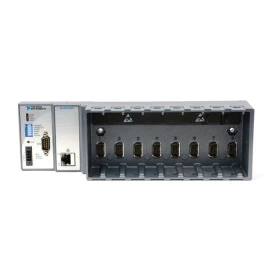
1. LEDs
2. RS-232 Serial Port
3. RJ-45 Ethernet Port 2 (cRIO-9074 Only)
4. RJ-45 Ethernet Port 1
This document describes how to connect the cRIO-9072/9073/9074 to a network and how to
use the features of the cRIO-9072/9073/9074.
Figure 1. CompactRIO cRIO-9072/9073/9074
1
POWER
FPGA
STATUS
USER1
SAFE MODE
CONSOLE OUT
IP RESET
NO APP
USER1
NO FPGA
RESET
V
INPUT
C
19-30 V
NC
20 W MAX
C
TRIGGER
6
2
NI cRIO-907x
LINK
10/
100
LINK
10/
100
5
5. SMB Connector (cRIO-9074 Only)
6. Power Connector
7. Reset Button
8. DIP Switches
3
4
Advertisement
Table of Contents

Subscribe to Our Youtube Channel
Related Manuals for National Instruments CompactRIO cRIO-9072


Summary of Contents for National Instruments CompactRIO cRIO-9072
- Page 1 USER MANUAL AND SPECIFICATIONS NI cRIO-9072/9073/9074 Reconfigurable Embedded Chassis with Integrated Intelligent Real- Time Controller for CompactRIO Figure 1. CompactRIO cRIO-9072/9073/9074 NI cRIO-907x POWER FPGA STATUS USER1 SAFE MODE CONSOLE OUT IP RESET NO APP USER1 NO FPGA LINK RESET...
-
Page 2: Safety Guidelines For Hazardous Locations
Safety Guidelines Operate the cRIO-9072/9073/9074 only as described in this document. Caution Do not operate the cRIO-9072/9073/9074 in a manner not specified in this document. Product misuse can result in a hazard. You can compromise the safety protection built into the product if the product is damaged in any way. If the product is damaged, return it to NI for repair. -
Page 3: Electromagnetic Compatibility Guidelines
Two M4 or number 10 panhead screws (for panel mounting only) • A number 2 Phillips screwdriver • Power supply Note Visit ni.com/info and enter the Info Code rdsoftwareversion determine which software you need to use the cRIO-9072/9073/9074. NI cRIO-9072/9073/9074 User Manual and Specifications | © National Instruments | 3... -
Page 4: Mounting The Compactrio Reconfigurable Embedded Chassis
Note The cRIO-9072/9073/9074 may be shipped with a clear protective film cover on the front panel. You can remove the film cover before installing the cRIO-9072/9073/9074. Mounting the CompactRIO Reconfigurable Embedded Chassis You can mount the chassis in any orientation on a 35 mm DIN rail or on a panel. Use the DIN rail mounting method if you already have a DIN rail configuration or if you need to be able to quickly remove the CompactRIO chassis. - Page 5 You will be unable to read the serial number after you have mounted the chassis. Caution Make sure that no I/O modules are in the chassis before mounting it. NI cRIO-9072/9073/9074 User Manual and Specifications | © National Instruments | 5...
-
Page 6: Mounting The Chassis On A Panel
Mounting the Chassis on a Panel Panel or wall mounting is the best method for applications that are subject to high shock and vibration. You can use the NI 9905 panel mount kit to mount the cRIO-9072/9073/9074 on a flat surface. Complete the following steps. Fasten the chassis to the panel mount kit using a number 2 Phillips screwdriver and two M4 ×... -
Page 7: Mounting The Chassis On A Din Rail
1.3 N · m (11.5 lb · in.). Figure 7. Installing the DIN Rail Clip on the cRIO-9072/9073/9074 Insert one edge of the DIN rail into the deeper opening of the DIN rail clip. NI cRIO-9072/9073/9074 User Manual and Specifications | © National Instruments | 7... -
Page 8: Installing C Series I/O Modules In The Chassis
Figure 8. One Edge of the DIN Rail Inserted in a Clip 1. DIN Rail Clip 2. DIN Rail 3. DIN Rail Spring Press down firmly on the chassis to compress the spring until the clip locks in place on the DIN rail. -
Page 9: Removing I/O Modules From The Chassis
Use a standard Category 5 (CAT-5) or better shielded, twisted-pair Ethernet cable to connect the chassis to an Ethernet hub, or use an Ethernet crossover cable to connect the chassis directly to a computer. NI cRIO-9072/9073/9074 User Manual and Specifications | © National Instruments | 9... -
Page 10: Connecting The Chassis To Earth Ground
Caution To prevent data loss and to maintain the integrity of your Ethernet installation, do not use a cable longer than 100 m. If you need to build your own cable, refer to the Cabling section for more information about Ethernet cable wiring connections. -
Page 11: Wiring Power To The Chassis
Optionally, you can connect the positive lead of another power supply to the other V terminal and the negative lead to one of the C terminals. Install the power connector on the front panel of the cRIO-9072/9073/9074 and tighten the connector screws. NI cRIO-9072/9073/9074 User Manual and Specifications | © National Instruments | 11... -
Page 12: Chassis Reset Options
These options determine how the chassis behaves when the controller is reset in various conditions. Use the RIO Device Setup utility to select reset options. Access the RIO Device Setup utility by selecting Start»All Programs»National Instruments»NI- RIO»RIO Device Setup. -
Page 13: Using The Internal Real-Time Clock
SMB connector of the cRIO-9072/9073/9074, you can use the GPS device to correct for drift of the system clock. For software that supports GPS drift-correction and other digital I/O through the SMB connector, go to ni.com/info and enter the Info Code criosmb NI cRIO-9072/9073/9074 User Manual and Specifications | © National Instruments | 13... -
Page 14: Configuring Dip Switches
Configuring DIP Switches Figure 13. DIP Switches SAFE MODE CONSOLE OUT IP RESET NO APP USER1 NO FPGA All of the DIP switches are in the OFF position when the chassis is shipped from National Instruments. SAFE MODE Switch The position of the SAFE MODE switch determines whether the embedded LabVIEW Real- Time engine launches at startup. -
Page 15: Ip Reset Switch
Pressing the RESET button resets the processor in the same manner as cycling power. Note The FPGA continues to run unless you select the Autoload on Any Device Reset boot option. Refer to the Chassis Reset Options section for more information. NI cRIO-9072/9073/9074 User Manual and Specifications | © National Instruments | 15... -
Page 16: Understanding Led Indications
Understanding LED Indications Figure 14. cRIO-9072/9073/9074 LEDs POWER FPGA STATUS USER1 POWER LED The POWER LED is lit while the cRIO-9072/9073/9074 is powered on. This LED indicates that the power supply connected to the chassis is adequate. FPGA LED You can use the FPGA LED to help debug your application or easily retrieve application status. -
Page 17: Troubleshooting Network Communication
Complete the following steps to restore the BIOS network settings of the chassis. Move the IP RESET and SAFE MODE switches to the ON position. NI cRIO-9072/9073/9074 User Manual and Specifications | © National Instruments | 17... -
Page 18: Rs-232 Serial Port
Push the RESET button to cycle power to the chassis. Configure the IP and other network settings in MAX. Move the IP RESET and SAFE MODE switches to the OFF position. Note If the chassis is restored to the BIOS network settings, the LabVIEW run-time engine does not load. -
Page 19: Reconfigurable Fpga
Reconfigurable FPGA cRIO-9072 FPGA type Xilinx Spartan-3 1M Number of flip-flops 15,360 Number of 4-input LUTs 15,360 Number of multipliers Available block RAM 432 kbits Number of DMA channels NI cRIO-9072/9073/9074 User Manual and Specifications | © National Instruments | 19... -
Page 20: Internal Real-Time Clock
cRIO-9073, cRIO-9074 FPGA type Xilinx Spartan-3 2M Number of flip-flops 40,960 Number of 4-input LUTs 40,960 Number of multipliers Available block RAM 720 kbits Number of DMA channels For information about the life span of the nonvolatile memory and about best practices for using nonvolatile memory, go to ni.com/info and enter the Info Code... -
Page 21: Safety Voltages
• IEC 61010-1, EN 61010-1 • UL 61010-1, CSA 61010-1 • EN 60079-0:2012, EN 60079-15:2010 • IEC 60079-0: Ed 6, IEC 60079-15; Ed 4 NI cRIO-9072/9073/9074 User Manual and Specifications | © National Instruments | 21... -
Page 22: Electromagnetic Compatibility
• UL 60079-0; Ed 5, UL 60079-15; Ed 3 • CSA 60079-0:2011, CSA 60079-15:2012 Note For UL and other safety certifications, refer to the product label or the Online Product Certification section. Electromagnetic Compatibility This product meets the requirements of the following EMC standards for electrical equipment for measurement, control, and laboratory use: •... -
Page 23: Environmental Management
National Instruments service representative. For more information about compliance with the EU Battery Directive 2006/66/EC about Batteries and Accumulators and Waste Batteries and Accumulators, visit ni.com/environment/ batterydirective. NI cRIO-9072/9073/9074 User Manual and Specifications | © National Instruments | 23... - Page 24 电子信息产品污染控制管理办法(中国 RoHS) National Instruments 符合中国电子信息产品中限制使用某些有害物 中国客户 质指令(RoHS)。关于 National Instruments 中国 RoHS 合规性信息,请登录 。(For information about China RoHS ni.com/environment/rohs_china compliance, go to ni.com/environment/rohs_china Cabling The following table shows the standard Ethernet cable wiring connections for both normal and crossover cables. Table 3. Ethernet Cable Wiring Connections...
-
Page 25: Worldwide Support And Services
United States, visit the Worldwide Offices section of ni.com/ niglobal to access the branch office websites, which provide up-to-date contact information, support phone numbers, email addresses, and current events. NI cRIO-9072/9073/9074 User Manual and Specifications | © National Instruments | 25... - Page 26 CONTAINED HEREIN AND SHALL NOT BE LIABLE FOR ANY ERRORS. U.S. Government Customers: The data contained in this manual was developed at private expense and is subject to the applicable limited rights and restricted data rights as set forth in FAR 52.227-14, DFAR 252.227-7014, and DFAR 252.227-7015. © 2007—2016 National Instruments. All rights reserved. 374639F-01 Mar16...
Need help?
Do you have a question about the CompactRIO cRIO-9072 and is the answer not in the manual?
Questions and answers