Table of Contents
Advertisement
Quick Links
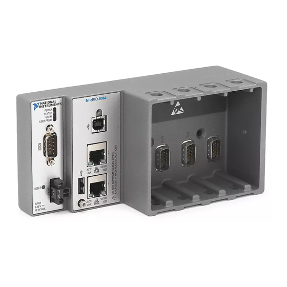
GETTING STARTED GUIDE
NI cRIO-9064
Embedded Real-Time Controller with Reconfigurable FPGA for C
Series Modules
This document describes how to begin using the NI cRIO-9064.
Safety Guidelines
Caution
Product misuse can result in a hazard. You can compromise the safety protection
built into the product if the product is damaged in any way. If the product is
damaged, return it to NI for repair.
Safety Guidelines for Hazardous Locations
The cRIO-9064 is suitable for use in Class I, Division 2, Groups A, B, C, D, T4 hazardous
locations; Class I, Zone 2, AEx nA IIC T4 and Ex nA IIC T4 hazardous locations; and
nonhazardous locations only. Follow these guidelines if you are installing the cRIO-9064 in a
potentially explosive environment. Not following these guidelines may result in serious injury
or death.
Do not operate the cRIO-9064 in a manner not specified in this document.
Advertisement
Table of Contents

Related Manuals for National Instruments cRIO-9064


Summary of Contents for National Instruments cRIO-9064
- Page 1 Safety Guidelines for Hazardous Locations The cRIO-9064 is suitable for use in Class I, Division 2, Groups A, B, C, D, T4 hazardous locations; Class I, Zone 2, AEx nA IIC T4 and Ex nA IIC T4 hazardous locations; and nonhazardous locations only.
-
Page 2: Special Conditions For Hazardous Locations Use In Europe And Internationally
Special Conditions for Hazardous Locations Use in Europe and Internationally The cRIO-9064 has been evaluated as Ex nA IIC T4 Gc equipment under DEMKO Certificate No. 12 ATEX 1202658X and is IECEx UL 14.0089X certified. Each device is marked 3G and is suitable for use in Zone 2 hazardous locations, in ambient temperatures of -20 °C ≤... -
Page 3: Electromagnetic Compatibility Guidelines
In addition, take precautions when designing, selecting, and installing measurement probes and cables to ensure that the desired EMC performance is attained. Preparing the Environment Ensure that the environment in which you are using the cRIO-9064 meets the following specifications. Operating temperature -20 °C to 55 °C... -
Page 4: Unpacking The Kit
2. USB A-to-B Cable 4. Getting Started Guide Installing Software on the Host Computer Before using the cRIO-9064, you must install the following application software and device drivers on the host computer in this order: LabVIEW 2014 SP1 or later LabVIEW Real-Time Module 2014 SP1 or later 4 | ni.com | NI cRIO-9064 Getting Started Guide... -
Page 5: Installing C Series Modules
Complete the following steps to install a C Series module. Verify that power is not connected to the I/O connector(s) on the C Series module. If the system is in a nonhazardous location, the cRIO-9064 can be powered on when you install modules. - Page 6 3. RS-232 Serial Port 7. Power Connector 4. RJ-45 Ethernet Port 2 8. RESET Button Connecting the cRIO-9064 to Ground You must connect the cRIO-9064 grounding terminal to the grounding electrode system of the facility. What to Use • Ring lug •...
- Page 7 Connecting the cRIO-9064 to Power The cRIO-9064 requires a 9 V to 30 V external power supply. The cRIO-9064 filters and regulates the supplied power and provides power for the C Series modules. The cRIO-9064 has one layer of reverse-voltage protection.
- Page 8 Power on the power supply. Powering On the cRIO-9064 When you power on the cRIO-9064 for the first time, the device boots into safe mode. The POWER LED illuminates, the STATUS LED illuminates briefly, and then the STATUS LED blinks twice every few seconds.
-
Page 9: Setting A System Password
The default username for the cRIO-9064 is . There is no default admin password for the cRIO-9064, so you must leave the password field blank when logging in until you set a system password. Right-click your system and select Web Configuration. - Page 10 Select NI Scan Engine from the software add-ons. Select any additional software to install. If you plan on using the cRIO-9064 with the LabVIEW FPGA Module, you can click Next. Click NI Scan Engine if you plan on using the cRIO-9064 without the LabVIEW FPGA Module.
-
Page 11: Verify The System Ip Configuration
Set a new DHCP connection by holding the RESET button down for 5 seconds. The STATUS LED repeats the same behavior from Step If the cRIO-9064 fails to set a new DHCP address, it assigns itself a link-local IP address. If the DHCP connection is successful and appropriate for your application, skip to Step In MAX, expand your system under Remote Systems. -
Page 12: Status Led Indicators
Table 4. STATUS LED Indicators LED Pattern Indication Blinks twice and The cRIO-9064 is in safe mode. Software is not installed, which is the pauses factory default state, or software has been improperly installed on the cRIO-9064. An error can occur when an attempt to upgrade the software is interrupted. -
Page 13: Where To Go Next
Table 4. STATUS LED Indicators (Continued) LED Pattern Indication Continuously blinks The cRIO-9064 has not booted into NI Linux Real-Time. The cRIO-9064 either booted into an unsupported operating system, was interrupted during the boot process, or detected an unrecoverable software error. - Page 14 CONTAINED HEREIN AND SHALL NOT BE LIABLE FOR ANY ERRORS. U.S. Government Customers: The data contained in this manual was developed at private expense and is subject to the applicable limited rights and restricted data rights as set forth in FAR 52.227-14, DFAR 252.227-7014, and DFAR 252.227-7015. © 2015 National Instruments. All rights reserved. 376901A-01 Oct15...
Need help?
Do you have a question about the cRIO-9064 and is the answer not in the manual?
Questions and answers