Advertisement
Quick Links
SPEED CONTROLLER
Mounting instructions and direetioft or use
DREHZAIilSTELLER
Montage- Øcd Gebruphamy is
RtGUL Mgt DE VITESS
Instruc ns d6 montage
9t
VAR A SSTYRNING
Mo ering och bruksanyli
KI RROSL UN S
Asennus- ja
HASTIGHETyRE9
Monterings- og b
CE
SAKRING I FUSE
TÄTNING / COVER SEAL
BORT-
TAGNING
AV RATT
KNOB
REMOVAL
MIN
(a)
4TY-0.5A MTY-1.
MTY-3. OA
Arry..2.
M210DIN
4
fts›.
For DIN-raik:' . .
mounting IP2 0
111210BOX
IP66 protected fdir
harsh environments
M210BOX/DIN - 10V or 3-SPEED
• 10V: For proportional speed control via an external 0-10VDC
input signal.
• 3-Speed: Select one of three individually presettable speeds
with an external switch, relay, timer, thermostat etc.
• Both types rated from 1.0A up to 4.0A.
M210 -RP
PID-Regulator with a 0-10V DC output.
Use with the M210BOX/DIN -10V
motor controller or a frequency converter.
• RP Differential low pressure regulator, 0-500Pa/1000Pa
• User friendly interface, 2 potential free Alarm outputs
• Adjustable PID-constants, Adjustable Min output
• IP66 protected
Power Limiter - ELSAVE
Reduce your main fuse rating- get lower bills for electricity!
•
Disconnects selected load(s) instead of blowing main fuse
•
ELSAVE I: "One step" - for main fuse 16 - 35 A
•
ELSAVE III: "Three steps" - for main fuse 16 - 63 A
•
Easy to install
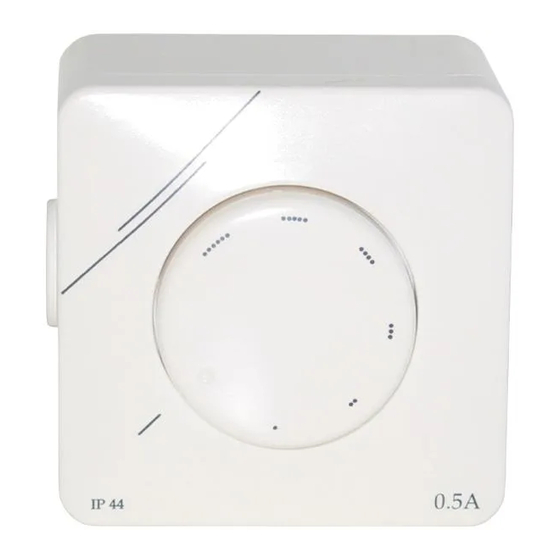
MT'Y-series, the classic one
One size for every need: MTY-0.5A, -1A, -2A, -3A and 4A
• Combined surface and flush mounting (MTY-4A surface
mounting only)
• Easy to install
• High protection class; IP44 or IP55.
AB
Contact us for more information
LSI Svenska
AB
Tel:
+46 (0) 23 273 00
Västermalmsvägen 10
Fax:
+46 (0) 23 142 70
SE-791 77 Falun
e-mail: Isi®Isi.se
SWEDEN
Internet: http://www.lsi.se
ELSAVE
SPEED CONTROLLER
0113)›
for single-phase motors
Voltage: 230V-, 50/60Hz
' AREAS'OrESE I..' ''
' ' , .-:::;',7,i.'
.
.
The speed controller is suitable for reducing airflow, noise etc, from single-phase
fans. The controller is only to be used together with motors that are suitable for
speed control. The motor used must be internally protected against over heating.
The connection marked .1. can for example be used for a damper,
indication lamp or as an inlet to the controller, bypassing the On/Off-function
in the turning knob.
-
ASSEMBLY' -
Flush mounting IP44 (not 114TY4 °Al.
Break mains voltage. Connect according to diagram below. Mount speed control to the wall with
connections pointing down. Turn on mains voltage and controller. Adjust minimum speed (see below)
and turn off controller. Mount cover and included cover seal with nut to the wall. Push knob in place and
turn it maximum CCW to the off-position.
Surface mounting. IP55 .
Break mains voltage. Mount surface mounting case to the wall. Included grommets should be used.
Connect according to diagram below. Use a thin object to obtain a hole in the centre of the cable entry
before pushing in the cable. Finally pull the cable gently outwards so that the cable seal is pointing
outwards. Mount inner case in surface mounting case with included screws. Turn on mains voltage and
controller. Adjust minimum speed (see below) and tum off controller. Mount cover with nut to surface
mounting case (without included packing). Push knob in place and turn it maximum CCW to the off-
position. When needed a 5mm hole for condensation water is to be drilled at the bottom of the surface
mounting case, see picture below.
..AINVP0 1 4 . 4
NUNI.
'
:,
Tum centre potentiometer max CCW. Adjust trimmer (MIN), placed under the plastic cover, so that,the
motor does not stop due to variations of mains voltage and restarts after power failure.
TROUBLE SHOOTING, CHANGE OF BUSE
in
ease of faulty operatinn please cheek that:
Correct voltage is applied, All connections are correct, The motor to be regulated is functioning,
Incoming mains fuse is OK, The fuse in the controller is OK.
change nf fuse;
Undo knob by first turning the knob clockwise beyond end stop and then pull. Remove the nut and the
cover. Remove fuse holder with a screwdriver. Change to the spare fuse. Put the details back in place.
Only use recommended fuses, (Approved, fast - with high breaking capacity) otherwise loss of warranty
will follow.
Warranty.
One year warranty against manufacturing defects. Contact supplier before return, batch - or serial
number should be stated.
' 'CONNECTIONS'
r c i 5-c''.. .
0
1
F :I. :
11 -- 19
e
e
ININCICIE
am
11111118CIE
L
L
BA
4-0 5m.
N
0
N
%iv
'
Condensation water hole.
0
0
DREHZAHLSTELLER
00)
fiir 1-Phasen Asynchronmotoren
Netzspannung: 230V-, 50/60 Hz
..,...„
NigiNG:
Der Drehzahlsteller ist geeignet ffir 1-phases ventilatoren zur luftmengen-
regulierung und verringern von luftgeräuschen. Der Drehzahlsteller darf
nur bei Motoren die fiir Drehzahlregulierung angepagt said beniitzt
werden. Der Motor soil einen eigenen Uberhitzungsschutz haben.
0
(1. pol 2): Extra Anschlun fur z.B. Klappen oder zum Anschluss ohne
unterbrochene Funktion been Rad.
MONTAGE-,
Unterputz IP44 (nicht MTY-4.0Al •
Strom ausschalten. Die Leitungen gemäss dem Schaltschema anschliessen. Den Regulator-Einsatz mit
den Kontakten nach unten in die Dose montieren. Strom einschalten. Die Minimum-Drehzahl mit dem
Trimmpotentiometer einstellen. Die Verkleidung (mit Dichtungsring) mit der Mutter an die
Unterputzdose anschrauben. Das Rad festdracken und aid "aus" stellen.
Oberputz 11'551
Strom ausschalten. Die Leitungen gemäss dem Schaltschema anschliessen. Vor dem Einziehen des
Kabels mit einem kleinen Werkzeug ein Loch in der Mille der Kabeldurchfiihrws stechen. Dariach das
Kabel so einziehen, dass die Durchfahrung nach aussen zeigt. Den Regulator-Einsatz mit den Kontakten
nach enters in die Dose montieren. Strom einschalten. Die Minimiun-Drelizahl mit dem
Trimmpotentiometer einstellen. Die Verkleidung (ohm Dichtungsring) mit der Mutter an die Dose
anschrauben. Das Rad festdriicken und aid "aus" stenen. Bei bedarf kann ein 5mm groges
Kondenswasserloch in die Unterseite der Dose gebohrt werden. Siehe bild unten.
-giNSTEELUN
7
Drehe das Rad aid die ldeinste Läge. Das Trimmpotenuometer (Minimum),plaziert tinter dem Deckel,
wird so eingestellt clan der Motor nach einem eventuellen Stromabbruch mit Minimum-Drehzahl startet.
,..ea.
.BEITEHLEX
AUSTAUSCIIEN DER SICHERUNG
.13..1
Fehler. Folgendes ist zu kontrollieren:- Ist die richtige Spannung angeschlossen? - Said alle
Kontakte richtig angeschlossen? - Funktioniert der angeschlossene Apparat? - Sind die Sicherung und die
Intemsicherung in Ordnung?
Amtausch der Internsicherung.
Das Rad wird im Uhrzeigersinn weiter als bis zwn Anstog gedreht und darm abgenommen.
Die Deckelmutter wird abgeschraubt und die Verkleidtmg entfemt. Der Sicherungshalter wird mit einem
Schraubenzieher entfemt und die Sicherung ausgetauscht. Im Sicherungshalter sitzt eine
Reservesicherwm. Zusammenbau in umgekehrter Reihenfolge. Nor die angegebene Sicherung
verwenden da sonst keine Garantie geleistet wird.
Garantie'
1 Jahr Garantie far Herstellungsfehler. Bei eventuellem Eintausch, kontakte einkaufsstelle, da die
Seriennummer angegeben werden mull
SCHALTSCHE
. .. . .
......
0
10
0
MI
R3
MI
~RI
INRICIREI
k
1.
=
el
k0 s p. :- .,A )
L_Ø
s
—f
0
0
Konaenswasserrom
0
Advertisement


Need help?
Do you have a question about the MTY-0.5A and is the answer not in the manual?
Questions and answers