
Related Manuals for SolaX Power X3-IES Series


Summary of Contents for SolaX Power X3-IES Series
- Page 1 X3-IES 4 kW / 5 kW / 6 kW / 8 kW 10 kW / 12 kW / 15 kW User Manual Version 2.0 www.solaxpower.com eManual in the QR code or at http://kb.solaxpower.com/...
- Page 2 No part of this manual may be reproduced, transmitted, transcribed, stored in a retrieval system, or translated into any language or computer language, in any form or by any means without the prior written permission of SolaX Power Technology (Zhejiang) Co., Ltd. Trademarks and other symbol or design (brand name, logo) that distinguishes the products or services offered by SolaX has been trademark protected.
- Page 3 Note: "X3-IES system" is the name of three-phase residential energy storage system. "X3-IES series inverter" (hereafter referred to as an "inverter") refers to the energy storage inverter that supports photovoltaic grid-connected. “4K"means the rated output power is 4kW. "T-BAT-SYS-HV-S50E” (hereafter referred to as an "T-BAT-SYS") is the name of battery system.
- Page 4 "X3-Matebox G2" is a device that integrates switches and a bidirectional electricity meter. This optional component can be installed when the X3-IES system is not connected in parallel, as it provides centralized management of the power supply to the home. Target Group The installation, maintenance and grid-related setting can only be performed by qualified personnel who...
- Page 5 mode.) Update Chapter 2.3.2 Control Panel and Indicators (Optimized the control logic and added a note that when an inverter is in an idle state, the work mode, the min SOC under different work modes and the charging periods can be reset.) Update Chapter 13 Technical Data (Added Australian certification parameters of rated AC output apparent power and Max.
-
Page 6: Table Of Contents
Table of Contents Safety ......................1 1.1 General Safety ........................1 1.2 Safety Instructions of PV, Inverter, Grid and Battery ..........2 1.2.1 Safety Instructions of PV ..................2 1.2.2 Safety Instructions of Inverter ................2 1.2.3 Safety Instructions of X3-Matebox G2 ............3 1.2.4 Safety Instructions of Utility Grid ..............4 1.2.5 Safety Instructions of Battery (T-BAT-SYS) ............4 1.3 Additional Safety Instructions ..................7... - Page 7 Mechanical Installation ................57 6.1 Mechanical Installation of X3-IES System..............57 6.2 Floor Mounting ........................59 6.2.1 One Tower for Floor Mounting ................59 6.2.2 Two Towers for Floor Mounting ..............71 6.3 Wall Mounting ........................72 6.3.1 One Tower for Wall Mounting ................72 6.3.2 Two Towers for Wall Mounting ................83 6.4 Battery Capacity Expansion ....................84 6.5 X3-Matebox G2 Mounting ....................85 Electrical Connection ................88...
- Page 8 9.7.2 Advance Setting ....................164 9.8 About .............................187 Operation on SolaX App and Web ............189 10.1 Introduction of SolaX Cloud App ..................189 10.2 Operation Guide on SolaXCloud App .................189 10.2.1 Downloading and installing App ..............189 10.3 Operation Guide on SolaX Cloud Web ...............190 Troubleshooting and Maintenance ............191 11.1 Troubleshooting .........................191 11.2 Maintenance ........................199...
-
Page 9: Safety
Safety General Safety The X3-IES system has been meticulously designed and thoroughly tested to comply with all relevant state and international safety standards. Nevertheless, like all electrical and electronic equipment, safety precautions must be observed and followed during the installation of the inverter to minimize the risk of personal injury and ensure a safe installation. -
Page 10: Safety Instructions Of Pv, Inverter, Grid And Battery
Safety Safety Instructions of PV, Inverter, Grid and Battery Save these important safety instructions. Failure to do so may result in damage to the devices and injury or even loss of life. 1.2.1 Safety Instructions of PV DANGER! Potential risk of lethal electrical shock associated with the photovoltaic (PV) system •... -
Page 11: Safety Instructions Of X3-Matebox G2
Safety WARNING! • During operation, avoid touching any parts of the inverter other than the DC switch and LCD panel (if any). • Never connect or disconnect the AC and DC connector while the inverter is running. • Prior to conducting any maintenance, turn off the AC and DC power and disconnect them from the inverter. -
Page 12: Safety Instructions Of Utility Grid
Safety DANGER! Lethal danger from electrical shock due to X3-Matebox G2 • Only qualified personnel can perform the installation, wiring, maintenance of the Matebox by following this document and the related regulations. WARNING! • During operation, avoid touching any parts of the matebox. Before powering on the device, turn on all breakers inside X3-Matebox G2. - Page 13 Safety Battery Handling Guide Do's • DO keep the battery module away from flammables materials, heat sources, and water sources; • DO keep the battery module out of reach of children and animals; • DO practice proper battery storage by keeping the battery module in a clean environment, free of dust, dirt and debris;...
- Page 14 Safety Response to Emergency Situations In case the battery module leaks electrolyte or any other chemical materials, or gas may be generated due to the leakage of battery module, be sure to avoid contact with the discharge at all times. In case of accidentally coming into contact with them, please do as follows: •...
-
Page 15: Additional Safety Instructions
Safety WARNING! • Do not crush or impact battery, and always dispose of it according to relevant safety regulations. • The battery module may catch fire when heated above 150°C/302°F. • In case of catching fire, the battery module will produce noxious and poisonous gases, and please keep away the battery. - Page 16 Safety All DC cables shall be installed in a distance as short as possible, and the positive and negative cables of the same input need to be bundled together to avoid causing loops in the system. Minimum distance installation and binding requirements also apply to auxiliary grounding and shielding grounding conductors.
-
Page 17: Product Overview
Load Figure 2-1 System overview diagram X3-IES System X3-IES series residential energy storage system integrates the inverter and a T-BAT-SYS into one. Inverter The X3-IES series inverter is a transformerless three-phase PV grid-connected inverter which is designed to convert the direct current generated from the PV modules into grid-compatible AC current and feeds the AC current to the utility grid or store in the batteries for future use. - Page 18 Product Overview PV Array The PV array works in MPPT mode. For 4.0 kW, 5.0 kW and 6.0 kW inverter, the number of PV string is two. For 8.0 kW, 10.0 kW, 12.0 kW and 15.0 kW inverter, the number of PV string is three. CT/ Meter A CT or meter is used for detecting the input and output current on the grid side.
-
Page 19: Supported Power Grid
Product Overview which facilitates the delivery of a larger, steady output power to important loads in both on-grid and off-grid conditions. The X3-PBOX-60kW-G2 can connect up to 6 inverters in one system, while up to 10 inverters can be connected with the X3-PBOX-150kW-G2 in one system. -
Page 20: Appearance
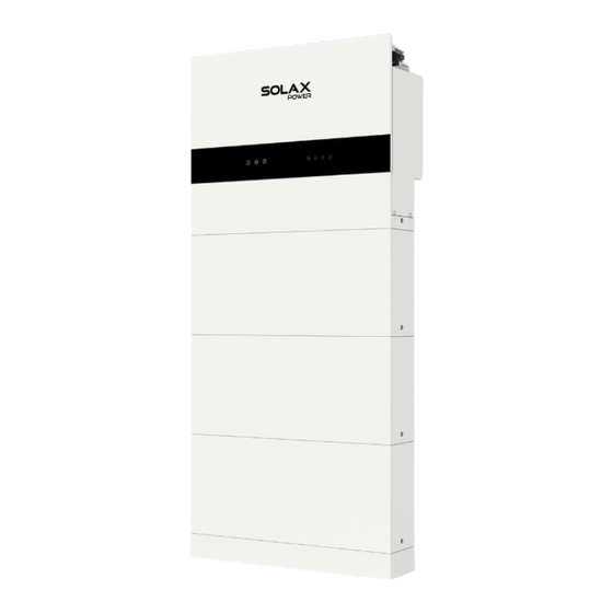
Product Overview Appearance LCD panel Upgrade/ port DC switch , button Type label Inverter electrical connection area Battery electrical Button , connection area switch Battery modules Base Figure 2-5 Apprearance Table 2-1 Desciption of appearance Item Description Type label clearly identifies the device type, serial number, specific Type label DC/AC parameters, certification, etc. -
Page 21: Dimensions
Product Overview Item Description USB port for upgrading and communication module connection. Upgrade/ Dongle Communication module includes a dongle/ 4G (optional) . DC switch Disconnect the PV input when necessary. Button Power on or off the inverter system. Inverter electrical Including PV terminals, battery terminals, AC terminals, connection area communication terminals, etc. - Page 22 Product Overview 150 mm 730 mm Figure 2-8 Battery module 75 mm 150 mm 730 mm Figure 2-9 Base 91.5 mm 167 mm 121 mm Figure 2-10 Series box...
- Page 23 Product Overview X3-Matebox G2 Dimensions 182 mm Figure 2-11 X3-Matebox G2...
-
Page 24: Control Panel And Indicators
Product Overview 2.3.2 Control Panel and Indicators Inverter control panel Timely output power Today’s energy Battery energy Power Today 0.0KWh Battery Normal Error indicator light Battery indicator light Down Status or error Operating indicator light Enter information Figure 2-12 Control Panel * The LCD screen in the whole passage is subject to the actual screen. - Page 25 Product Overview Table 2-3 Definition of keys Definition ESC key Exit from the current interface or function Up key Move the cursor to the upper part or increase the value Down key Move the cursor to the lower part or decrease the value Enter key Confirm the selection Battery indicators...
- Page 26 Product Overview Status Description The status light comes on solid green light, and the state of SoC power Charging indicators depends on the actual situation. For details, please refer to the following “Figure 2-5 Indicator information while charging”. The status light comes on solid green light, and the state of SoC power Discharging indicators depends on the actual situation.
- Page 27 Product Overview Fault SoC1 SoC2 SoC3 SoC4 Temperature fault (high temperature, low Flash Flash temperature) Current fault (overcurrent charging, Flash overcurrent discharging) Hardware fault (MCU fault, external short circuit fault, AFE fault, voltage sampling Flash Flash disconnection fault, temperature sampling, or current sensor default) Relay fault Flash...
- Page 28 Product Overview Black Start The equipment can provide Black Start capacity, meaning that our energy storage inverter and battery can continue to run even if the power grid and photovoltaic panel are out of service. The startup procedure for Black Start is as follows: First stage: in case of pressing and holding the BMS BUTTON for less than 20 •...
-
Page 29: Ports Of Devices Of X3-Ies System
Product Overview 2.3.3 Ports of Devices of X3-IES System Ports of Inverter Right side Figure 2-14 Ports of an inverter Table 2-8 Description of ports Item Description DC switch: Turn on or turn off to connect or disconnect the PV input PV connection port: Connect PV cables ... - Page 30 Product Overview Ports of Battery (T-BAT-SYS) • HEAT Left side Right side Figure 2-15 Ports of a BMS Table 2-9 Description of ports Item Description The hot-plug interface connected to the inverter The hot-plug interface connected to the battery module BAT BUTTON: Start system BAT SWITCH: A switch for battery's input and output “DIP Switch”...
- Page 31 Product Overview Item Description HEAT: Connect the HEAT port of the series box (if any), or a short-circuit plug must be inserted into the port • DIP Switch A DIP Switch is equipped on the BMS. After opening HEAT Figure 2-16 DIP switch Table 2-9 Definition of DIP switch Description DIP Switch 1...
- Page 32 Product Overview • Battery module A hot-plug interface that is connected to the bottom of the battery module or the BMS. A hot-plug interface that is connected to the bottom of the battery module or the Base. Figure 2-17 Ports of a battery module •...
- Page 33 Product Overview • Series box The series box shall be installed in case the battery modules purchased exceed 4 sets (including 4). Figure 2-19 Ports of a series box Table 2-10 Description of ports Item Description GND: Connect to the grounding port of the BMS. COM: Connect to the COM port of the BMS.
-
Page 34: Symbols On The Label And Devices Of X3-Ies System
Product Overview Item Description Grid(INV): Connect to the Grid port of the inverter. Meter/CT: Connect to the Meter/CT port of the inverter when a meter is selected. Connect to the Meter/CT port of the inverter with CTs connected in between when CTs are selected. Grid: Connect to the power grid. - Page 35 Product Overview Symbol Description Observe enclosed documentation. The inverter and battery modules can not be disposed together with the household waste. Disposal information can be found in the enclosed documentation. Do not dispose of the battery module together with household waste. The battery system must be disposed of at a proper facility for environmentally-safe recycling.
-
Page 36: Working Principle
Product Overview Working Principle 2.4.1 Working mode The inverter has two configurable working periods: allowed discharging period and forced charging period. For how to set the two working periods, please refer to “9.7 Settings” to set working modes. The default value of allowed discharging period is 00:00~23:59, and the default value of forced charging period is 00:00~00:00(closed in default). - Page 37 Product Overview Feed-in Priority The feed-in priority mode is suitable for areas with high feed-in subsidies, but has feed-in power limitation. The power of PV will supply the loads first, and surplus power will feed into the grid, then the remaining power will charge the battery.
- Page 38 Product Overview Peak Shaving mode Peak Shaving mode is set for leveling out peaks in electricity use. System is controlled to charge up during off-peak hours and discharged during peak hours. Peak Shaving Mode Power (Assuming peak power from 7:00 to 9:00 and from 18:00 to 23:00) Idea: Leveling out peaks in electricity use.
- Page 39 Product Overview TOU mode In the TOU mode, different working modes, i.e Self-use, Charging, Discharging, Peaking shaving and Battery off can be set for different time periods in accordance with actual needs and environment conditions through SolaX Cloud App or Web. The day can be divided into up to 24 time slots, and the minimum time slot is 15 minutes, independent working mode can be set for each time slot.
-
Page 40: Circuit Diagram
Product Overview 2.4.2 Circuit Diagram The inverter is equipped with multi-channel MPPT for DC input to ensure maximum power even under different photovoltaic input conditions. The inverter unit converts DC into AC that meets the requirements of the power grid and feeds it into the power grid. The lightning arrester at AC / DC side can realize the function of surge protection. - Page 41 Product Overview System Diagram A (applicable to most countries) Dongle Inverter Breaker Main Breaker BAT+ BAT- BMS METER/CT Grid T-BAT-SYS ⋯ ⋯ Loads Loads ⋯ ⋯ N-BAR for loads N-BAR for EPS loads Distribution box Figure 2-24 System diagram without X3-Matebox G2 for most countries...
- Page 42 Product Overview System Diagram B (applicable to most countries) Dongle X3-Matebox G2 Inverter PE-BAR GRID GRID (INV) (INV) LOAD R S T N R S T N R S T N R S T N BAT+ BAT- BMS METER/CT PE-BAR Meter T-BAT-SYS Connect to loads...
- Page 43 Product Overview System Diagram C (applicable to Australia) Dongle Inverter Breaker Main Breaker BAT+ BAT- BMS METER/CT Grid T-BAT-SYS Loads Loads N-BAR for loads N-BAR for EPS loads Distribution box Figure 2-26 System diagram without X3-Matebox G2 for Australia...
- Page 44 Product Overview System Diagram B (applicable to Australia) Dongle X3-Matebox G2 Inverter PE-BAR GRID (INV) (INV) LOAD GRID R S T N R S T N R S T N R S T N BAT+ BAT- BMS METER/CT PE-BAR Meter T-BAT-SYS Connect to loads R S T N...
-
Page 45: Micro Grid
Product Overview Micro Grid Due to the islanding effect, on-grid inverters are unable to work off-grid. This feature makes users lose the PV energy of on-grid inverters when off-grid. Micro-grid is a function that makes hybrid inverters simulate the grid to activate an on-grid inverter during off-grid. By connecting the on-grid inverter to the EPS port of the hybrid inverter, the hybrid inverter is able to use PV or battery energy to activate the on-grid inverter when utility is lost. -
Page 46: Transportation And Storage
Transportation and Storage If the devices of X3-IES system is not put into use immediately, the transportation and storage requirements needs to be met: Transportation • Observe the caution signs on the packaging of the devices before transportation. • Pay attention to the weight of the devices. Be cautious to avoid injury when carrying the devices. -
Page 47: Preparation Before Installation
Preparation before Installation Selection of Installation Location The installation location selected for the devices of X3-IES system is quite critical in the aspect of the guarantee of machine safety, service life and performance. • It has the IP66 ingress protection, which allows it to be installed outdoor; •... - Page 48 Preparation before Installation • Install the inverter 500 meters away from sea and at the place where the sea breeze does not directly hit Sea breeze Inverter 300m 500m 1,000m Over 1,000m Figure 4-1 Recommended installation position Sea breeze Inverter 300m 500m 1,000m Over 1,000m...
-
Page 49: Installation Options
Installation Options NOTICE! • X3-IES series inverter can match 2~6 battery modules. "Option A/ B/ C" is for one tower and "option D/ E/ F/ G" is for two towers. • Generally, up to three battery modules in one tower are recommended. Four battery modules in one tower can be selected when installation space is limited. - Page 50 Preparation before Installation Two Towers >300 mm >300 mm Option E Option D >300 mm >300 mm Option F Option G Figure 4-4 Installation options for two towers Table 4-1 Net weight and dimensions of components Option Option Option Option D Option E Option F Option G...
- Page 51 • The maximum net weight of an inverter (37kg) is taken as an example. • The net weight of inverters of different powers differs. Please check the specific net weight of the X3-IES series inverter when calculating the total weight of the devices of X3-IES system.
-
Page 52: Installation Carrier Requirement
Preparation before Installation Table 4-6 Net weight and dimensions of T-BAT-SYS Battery Base Series box Cover module Length (mm) Width (mm) Height (mm) 91.5 Net weight (kg) 4.1.3 Installation Carrier Requirement The mounting location must be suitable for the weight and dimensions of the product and the support surface for installation must be made of a non-flammable material. -
Page 53: Clearance Requirement
Preparation before Installation 4.1.4 Clearance Requirement To guarantee proper heat dissipation and ease of disassembly, the minimum space around the inverter must meet the standards indicated below. • For installations with multiple devices, make sure to leave a minimum space of 300 mm between the left and right tower and 300 mm from the ceiling. -
Page 54: Tools Requirement
Preparation before Installation Tools Requirement Installation tools include but are not limited to the following recommended ones. If necessary, use other auxiliary tools on site. Measuring tape Utility knife Hammer drill Multimeter Flat-head Allen key Marker Cross screwdriver screwdriver Crimping tool for Crimping tool Wire stripper Diagonal pliers... -
Page 55: Additionally Required Materials
Preparation before Installation Additionally Required Materials Battery Table 4-7 Additionally required wires Required Material Type Diameter External diameter: over Corrugated pipe Protective pipe 67.2 mm Inverter Table 4-8 Additionally required wires Conductor Required Material Type Cross-section 6 mm² dedicated PV wire with a voltage rating of PV wire 1000 V, a temperature... - Page 56 Preparation before Installation Table 4-10 EPS wire and breaker recommended X3-IES X3-IES X3-IES X3-IES Model -10K -12K -15K Five- core wire 4-6 mm² 4-6 mm² 4-6 mm² mm² mm² mm² mm² (copper) Breaker 16 A 16 A 16 A 20 A 25 A 32 A 32 A...
-
Page 57: Unpacking And Inspection
Unpacking and Inspection The number of battery cartons will be different due to different modes of mounting. Therefore, please check whether the number of cartons received are correct before unpacking. For details, please refer to the following table. Table 5-1 Number of cartons One Tower Two Towers A BMS carton, and carton(s) of... - Page 58 Unpacking and Inspection • Unpacking the BMS and battery module(s) according to the following figures. If there are other cartons, such as the base support carton, and series box carton, the unpacking procedure can also be referred to the following figures. Figure 5-2 Unpacking the BMS Figure 5-3 Unpacking the battery module •...
-
Page 59: Scope Of Delivery
Unpacking and Inspection Scope of Delivery Inverter Inverter Bracket AC connector Waterproof connector with a RJ45 Communication Negative PV connectors & Positive PV connectors & connector & ferrules PV pin contact PV pin contact M5*14 screws M5*10 screws RJ45 terminal Expansion tubes RJ45 connector Self-tapping screws... - Page 60 Unpacking and Inspection Items Quantity 2 pairs for 4.0 ~ 6.0 kW inverter; Positive PV connectors & PV pin contacts 3 pairs for 8.0 ~ 15.0 kW inverter 2 pairs for 4.0 ~ 6.0 kW inverter; Negative PV connectors & PV pin contacts 3 pairs for 8.0 ~ 15.0 kW inverter Waterproof connector with RJ45...
- Page 61 Unpacking and Inspection Expansion bolt Angle bracket M5*14 Phillips Tapping cheese head screw Adjustable bracket screw Base System performance Expansion screw label Document Rotation wrench Table 5-3 Packing list of BMS Item Quantity 1 pc Base 1 pc Angle brackets 4 pcs Adjustable brackets 4 pcs...
- Page 62 Unpacking and Inspection Battery Module M5*14 Phillips cheese Battery module head screw Document Table 5-4 Packing list of battery module Item Quantity Battery module 1 pc M5*14 Phillips cheese head screws 2 pcs Document 1 pc Base Support (For wall mounting only) M5*20 Phillips countersunk head Expansion screw...
- Page 63 Unpacking and Inspection Series Box (For two towers only) Expansion bolt Angle bracket Series Box Tapping M5*14 Phillips cheese screw Adjustable bracket head screw Base Power cable (black) Communication cable Power cable (red) Expansion screw Grounding cable Heater cable Cover Document Table 5-6 Packing list of Series Box Item...
- Page 64 Unpacking and Inspection X3-Matebox G2 Expansion tubes & self-tappting screws X3-Matebox G2 Bracket Keys 14 mm² and 10 mm² 14 mm² and 10 mm² ferrules OT terminals Document Table 5-7 Packing list of X3-Matebox G2 Items Quantity X3-Matebox G2 1 pc Bracket 1 pc Keys...
-
Page 65: Mechanical Installation
Mechanical Installation Mechanical Installation of X3-IES System Figure 6-1 Correct installtion angle NOTICE! • The wall selected for installation should be flat and perpendicular to the floor. The mechanical installation of the X3-IES system supports floor mounting and wall mounting. The two installation methods are illustrated below. Option B with three battery modules is taken as an example. - Page 66 Mechanical Installation WARNING! • Only the qulalified personel can perform the mechanical installation following the local standards and requirements. • Check the existing power cables or other piping in the wall to prevent electric shock or other damage. CAUTION! • Always be aware of the weight of the devices. Personal injuries may result if the devices are lifted improperly or dropped while being transported or mounted.
-
Page 67: Floor Mounting
Mechanical Installation Floor Mounting 6.2.1 One Tower for Floor Mounting NOTICE! • The mode of floor mounting is given priority for installation. • Take the installation procedure for Option B (three battery modules in one tower) as an example. Step 1: Remove dustproof covers from the base, battery module(s) and BMS before conducting installation. - Page 68 Mechanical Installation Step 3: Rotate the adjustment screws clockwise to ensure that it is even. Turn clockwise to lower the base, and turn anticlockwise to raise the base. Figure 6-5 Rotating adjustment screws NOTICE! • Use a spirit level to measure both side of the base to ensure that the base is even; •...
- Page 69 Mechanical Installation Step 5: Attach the angle bracket and adjustable bracket together by using M5*14 screws, but do not tighten them for a while. Figure 6-7 Attaching two brackets Step 6: Place the assembled bracket on the wall, align the hole to the hole on the battery module;...
- Page 70 Mechanical Installation Step 7: Remove the assembled bracket, and then drill two holes at a depth of more than 60 mm in the concrete wall by using a drill (Ø10 mm). Concrete Wall Ø10 mm Drill 90° > 60 mm Figure 6-9 Drilling holes NOTICE! •...
- Page 71 Mechanical Installation Tapping screw M5*14 8-10 N·m 2.2-2.5 N·m Figure 6-11 Securing the assembled bracket NOTICE! • If the base is shifted before securing assembled bracket, move it to its original location according to the mark previously drawn. Step 9: Place a battery module on the base. Figure 6-12 Placing the battery module NOTICE! •...
- Page 72 Mechanical Installation Step 10: Insert and tighten M5*14 screws on both sides (torque: 2.2-2.5 N·m). M5*14 2.2-2.5 N·m Figure 6-13 Tightening screws NOTICE! • Please make sure that the corners and edges of the base and battery module are aligned before tightening screws. Step 11: Place the second and third battery modules, and make sure that the corners and edges of the battery modules are aligned.
- Page 73 Mechanical Installation brackets on the wall; 3. Align the holes on the positioning cardboard with the dots in the second row on the wall; 4. Mark the dots where "X3-IES" is noted on the positioning cardboard. Figure 6-15 Attaching two brackets Figure 6-16 Marking the position of BMS Figure 6-17 Aligning the positioning cardboard with the dots on the wall...
- Page 74 Mechanical Installation Figure 6-18 Marking the position of the brackets of the inverter Step 13: Drill the holes for the BMS and the inverter and tighten them. 1. Remove the assembled brackets on the battery module, and then drill the four holes at a depth of more than 60 mm in the concrete wall by using a Drill (Ø10 mm);...
- Page 75 Mechanical Installation Figure 6-20 Knocking expansion tubes into the wall As for securing brackets, refer to Step 8. Figure 6-21 Tightening the BMS brackets NOTICE! • An electric drill dust collector is recommended. • To prevent dust from being released into the hot plug when drilling holes, users may use the package bag of the device or other materials to fully cover the battery module.
- Page 76 Mechanical Installation Step 14: Place the BMS, and then tighten the M5*14 screws on both sides (torque: 2.2-2.5 N·m) Figure 6-22 Placing the BMS M5*14 2.2-2.5 N·m Figure 6-23 Tightening M5 screws NOTICE! • Please make sure that the corners and edges of the BMS and battery module are aligned before tightening screws.
- Page 77 Mechanical Installation Step 15: Remove the dustproof cover from the bottom of the inverter. Figure 6-24 Removing the dustproof cover Step 15: Install the inverter on the BMS. Figure 6-25 Installing the inverter NOTICE! • At least two persons are required to move the inverter.
- Page 78 Mechanical Installation Step 16: Lock the screws on both sides of the inverter with the BMS. M5 * 14 2±0.1 N·m Figure 6-26 Locking the inverter with the BMS Step 17: Lock the inverter brackets on both sides of the inverter. 1.
-
Page 79: Two Towers For Floor Mounting
Mechanical Installation 6.2.2 Two Towers for Floor Mounting NOTICE! • Take the installation procedure for option G as an example. Step 1: As for the installation steps for the following figure, please refer to the installation procedure for “6.2.1 One Tower for Floor Mounting” (Steps 1 to 19). -
Page 80: Wall Mounting
Mechanical Installation Wall Mounting 6.3.1 One Tower for Wall Mounting NOTICE! • Take the installation procedure for three battery modules as an example. Step 1: Remove dust covers from the base, battery module(s) and BMS before conducting installation. Base Battery module Figure 6-30 Removing dust covers Step 2: Tighten M5*8 screws on both sides to attach the base support and transverse plate together (torque: 2.2-2.5 N·m). - Page 81 Mechanical Installation Step 3: Place the assembled base support and transverse plate on the wall, check the cylindrical plastic bubble spirit level on the transverse plate. If the bubble isn't in the centre, slightly bow it to the horizontal. Then circle along the inner ring of the four holes. cylindrical plastic bubble...
- Page 82 Mechanical Installation Step 5: Place the assembled base support and transverse plate on the wall again, and check whether the bubble is in the centre. Attach the expansion screws to such four holes, hit it by using rubber mallet, and then tighten it by using torque wrench (torque: 20-25 N·m) 20-25 N·m Figure 6-34 Tightening expansion screws...
- Page 83 Mechanical Installation Step 7: Place the battery module on the base. Figure 6-36 Placing battery module NOTICE! • At least two persons are required to move the battery module. • Please ensure that the side with "R" shall be against the wall. Step 8: Insert and tighten M5*14 screws on both sides (torque: 2.2-2.5 N·m).
- Page 84 Mechanical Installation Step 9: Place the second and third battery modules, and make sure that the corners and edges of the battery modules are aligned. Step 8 Steps 7 to 8 Figure 6-38 Placing battery modules Step 10: Locate the position of the BMS and the inverter. 1.
- Page 85 Mechanical Installation Figure 6-40 Marking the position of BMS Figure 6-41 Aligning the positioning cardboard with the dots on the wall Figure 6-42 Marking the position of the brackets of the inverter...
- Page 86 Mechanical Installation Step 11: Drill the holes for the BMS and the inverter and tighten them. 1. Remove the assembled brackets on the battery module, and then drill the four holes at a depth of more than 60 mm in the concrete wall by using a drill (Ø10 mm);...
- Page 87 Mechanical Installation 8-10 N·m Tapping screw M5*14 2.2-2.5 N·m Figure 6-45 Securing the assembled bracket NOTICE! • An electric drill dust collector is recommended. • To prevent dust from being released into the hot plug when drilling holes, users may use the package bag of the device or other materials to fully cover the battery module.
- Page 88 Mechanical Installation M5*14 2.2-2.5 N·m Figure 6-47 Tightening M5 screws NOTICE! • Please make sure that the corners and edges of the BMS and battery modules are aligned before tightening screws. Step 13: Remove the dustproof cover from the bottom of the inverter. Figure 6-48 Removing the dustproof coverr...
- Page 89 Mechanical Installation Step 14: Install the inverter on the BMS. Figure 6-49 Installing the inverter NOTICE! • At least two persons are required to move the inverter. Step 15: Lock the screws on both sides of the inverter with the BMS. M5 * 14 2±0.1 N·m Figure 6-50 Locking the inverter with the BMS...
- Page 90 Mechanical Installation Step 16: Lock the inverter brackets on both sides of the inverter. 1. Tighten but not lock the self-tapping screws into the wall. 2. Lock screws on the inverter. 3. Lock screws into the wall. ST 6.3 2±0.1 N·m M5 * 10 2±0.1 N·m Figure 6-51 Locking the inverter brackets...
-
Page 91: Two Towers For Wall Mounting
Mechanical Installation 6.3.2 Two Towers for Wall Mounting NOTICE! • Take the installation procedure for six battery modules as an example. Step 1: As for the installation steps for the following figure, please refer to the installation procedure for “6.3.1 One Tower for Wall Mounting” (Steps 1 to 17). -
Page 92: Battery Capacity Expansion
Mechanical Installation Step 2: Place the series box, insert and tighten M5*14 screws, with totalling 4 screws (torque: 2.2-2.5 N·m). M5 * 14 2.2-2.5 N·m Figure 6-53 Placing the series box NOTICE! • The side of the series box with "R" shall be against the wall. •... -
Page 93: X3-Matebox G2 Mounting
Mechanical Installation X3-Matebox G2 Mounting NOTICE! • "Matebox" refers to X3-Matebox G2. • The horizonal distance between X3-IES and X3-Matebox G2 should be no more than 100 cm. • For the height of X3-Matebox G2, the bottom of the ports of X3-Matebox G2 should be a little bit higher than the outlet of the inverter. - Page 94 Mechanical Installation Ø10 drill bit Depth: > 60 mm Figure 6-55 Drilling holes NOTICE! • When drilling holes, make sure the already installed part is covered to prevent dust from falling onto the device. Step 3: Knock expansion tubes into the holes on the wall with a rubber hammer, put the wall-mounting bracket on the wall again and then align the bracket with the drilled holes on the wall.
- Page 95 Mechanical Installation 2±0.1 N·m Figure 6-57 Securing the bracket Step 4: Hang the device on the wall-mounting bracket with two people's help. Ensure that the device is well fit with the bracket and hanged securely. Figure 6-58 Hanging the matebox on the bracket...
-
Page 96: Electrical Connection
Electrical Connection Electrical Connection of Battery 7.1.1 Details of Cables Communication cable: There are two terminals at both ends. One connects to the COM port of the BMS, and the other connects to the COM port of the series box. Figure 7-1 Communication cable Heater cable: There are two terminals at both ends. -
Page 97: Wiring Procedure
Electrical Connection NOTICE! • The above-mentioned cables are delivered with the Accessories of Series Box. 7.1.2 Wiring Procedure WARNING! • Only the qualified personnel can perform the wiring. • Follow this manual to wire connection. The device damage caused by incorrect cabling is not in the scope of warranty. - Page 98 Electrical Connection Step 1: Before conducting wiring between the BMS and series box, press and hold the lock button to unplug the short power cable. HEAT Short power cable HEAT Lock button Figure 7-6 Removing short power cable Step 2: Rotate the waterproof cap anti-clockwise to remove it. And rotate the short- circuit plug anti-clockwise.
- Page 99 Electrical Connection HEAT port short-circuit plug Figure 7-8 Closing short-circuit plug NOTICE! • Press and hold the lock button while unplugging the power cable, or it cannot be pulled out. • Don't violently remove the short-circuit plug before the arrow on the rotating ring is aligned with the arrow on the panel.
- Page 100 Electrical Connection Step 3: Connect B+ of the BMS to B+ of the series box; Connect B- of the BMS to B- of the series box; Connect COM port of the BMS to COM port of the series box; Connect HEAT port of the BMS to HEAT port of the series box; Connect the grounding port of the BMS to the grounding port of the series box.
- Page 101 Electrical Connection Step 4: Pull cables through pipes after connecting cables to the BMS. Pull the power cable (red) and heater cable through pipe 1, and pull the power cable (black), communication cable and grounding cable through pipe 2. Pipe 2 Pipe 1 Figure 7-10 Pulling cables NOTICE!
- Page 102 Electrical Connection Step 6: Firstly rotate the rotating ring until the arrow on it is aligned with the arrow on the panel before removing the short-circuit plug, and then insert the heater cable into the HEAT port and rotate clockwise to close it. Align the groove according to the arrows...
-
Page 103: Installation Of Cover
Electrical Connection 7.1.3 Installation of Cover After finishing wiring, push the cover to the series box, and tighten M5*14 screws on both sides to secure the cover (torque: 2.2-2.5 N·m). M5*14 2.2-2.5 N·m Figure 7-13 Tightening M5 screws NOTICE! • Please make sure that the corners and edges of the cover and battery modules are aligned before tightening screws. -
Page 104: Electrical Connection Of Inverter
Electrical Connection Electrical Connection of Inverter DANGER! • (Without X3-Matebox G2) Before electrical connection, make sure the DC switch of the battery (T-BAT-SYS), the inverter DC switch, the AC breaker and the EPS breaker are turned off. Otherwise, an electrical shock may be caused by high voltage, resulting in serious personal injury or death. -
Page 105: Grid And Eps Connection
Electrical Connection 7.2.2 Grid and EPS Connection NOTICE! • Before connecting the inverter to the grid, approval must be received by the local utility as required by national and state interconnection regulations. The inverter has an EPS function. When the grid is connected, the inverter outputs go through the Grid port, and when the grid is disconnected, the inverter outputs go through the EPS port. - Page 106 Electrical Connection Wiring procedures Figure 7-15 Well connected Grid & EPS cables Step 1: Prepare a Grid cable (five-core wire) and an EPS cable (five-core wire) and strip the insulation jacket as below. wire cutter 65~72 mm wire stripper Figure 7-16 Striping the Grid and EPS cables Step 2: Insert L1, L2, L3 and PE wires of the Grid and EPS cables into ferrules.
- Page 107 Electrical Connection NOTICE! • For a 5.0~8.0 kW inverter, please select suitable Grid and EPS ferrules from theinverter accessory pack in accordance with the diameter of the Grid and EPS cables actually used. Step 3: Loosen the swivel nut of the AC connector, pull out the rubber sealing stopper. Figure 7-18 Disassembling the AC connector »...
- Page 108 Electrical Connection Step 4: Press the tool into the terminal block in the AC connector and use a screwdriver to poke the terminal block out from the other end of the AC connector. Figure 7-21 Poking the terminal block out of the AC connector Step 5: Connect Grid and EPS cables to the AC connector.
- Page 109 Electrical Connection Step 6: Put the terminal block, the rubber sealing stopper into the AC connector. Screw the swivel nut tightly. Click! Figure 7-24 Wiring the AC connector Step 7: Pull up the latch on the AC connector. Figure 7-25 Pulling up the latch Step 8: Remove the dustproof cover on the Grid &...
- Page 110 Electrical Connection Figure 7-27 Plugging the AC connector into the port on the inverter outer side PE L1 L2 L3 N GRID inner side Allen key 2.5±0.1 N·m Figure 7-28 Tightening the lock on the AC connector...
-
Page 111: Pv Connection
Electrical Connection 7.2.3 PV Connection DANGER! • High DC voltage will be generated by PV modules when exposed to sunlight. Death or lethal injuries will occur due to electric shock. • Make sure the DC switch are turned off and AC breaker are disconencted from the inverter before PV connection. - Page 112 Electrical Connection Wiring procedures Figure 7-30 Well connected PV cables Step 1: Strip 7 mm insulation jacket off PV cables. Insert the stripped ends of PV cables (+/-) into PV pin contacts (+/-). Ensure that the stripped cable and the PV pin contact are of the same polarity.
- Page 113 Electrical Connection MC4 crimping tool Figure 7-33 Crimping cables with PV pin contacts Step 2: Thread PV cables through swivel nuts and insert cables (+/-) into PV connectors (+/-) until a "Click" is heard. Gently pull cables backward to ensure firm connection.
- Page 114 Electrical Connection Figure 7-36 Tightening swivel nuts of PV connectors Step 3: Check whether the PV connectors have the correct polarity. Use a multimeter to measure the positive and negative voltage of the assembled PV connectors. Make sure the open circuit voltage does not exceed the input limit of 950 V. Figure 7-37 Measuring the voltage of PV connectors NOTICE! •...
- Page 115 Electrical Connection NOTICE! • Please ensure the AC breaker is disconnected and secure against reconnection. • Please ensure the DC switch of the inveter and the battery is switched off. Step 5: Connect the assembled PV connectors to corresponding ports on the inverter until there is an audible click.
-
Page 116: Communication Connection
Electrical Connection 7.2.4 Communication Connection COM and CT/Meter ports are for the communication function of the inverter. Communication Port Introduction Table 7-1 Description of COM PARALLE_SYNC1 PARALLE_SYNC2 EPSBOX_RELAY_VCC PARALLE485A Parallel signal out- PARALLE485B GND_COM Parallel signal port CAN_L (RJ45) CAN_H PARALLE_SYNC1 PARALLE_SYNC2 Parallel signal input... - Page 117 Electrical Connection Icon Definition Function Comment Parallel signal port CAN_L Parallel signal input (RJ45) CAN_H DRM1/5 DRM2/6 Logical interface is DRM3/7 Logic interface for Australia (AS4777) signal DRM4/8 and other standards +3.3V_COM COM/DRM0 RS485 differential communication with remote 485A signal-A SolaX's datahub, EV-Charger and oth- RS485 differential...
- Page 118 Electrical Connection Parallel Connection (P1/P2 Port) The inverter provides the parallel connection function. Up to 10 inverters can be connected in one system with an X3-PBOX-60kW-G2/ X3-PBOX-150kW-G2 (hereafter referred to as X3-PBOX device). Up to 3 inverters can be connected in one system if no X3-PBOX device is equipped.
- Page 119 Electrical Connection • Diagram 2: System diagram without SolaX X3-PBOX device N-BAR for EPS loads Loads Breaker PE-BAR COM (P1) Grid EPS COM (P1) Grid EPS Grid EPS Figure 7-41 System diagram without SolaX X3-PBOX device WARNING! • Many cables are connected in these parallel systems, therefore it is strongly required that cables must be connected according to correct line sequence (R-R, S-S, T-T, N-N).
- Page 120 Electrical Connection Parallel connection diagram • Diagram 1: Parallel connection with SolaX X3-PBOX device » Use standard network cables for P2-P1 connection. » Connect Master inverter P1 to the COM port of X3-PBOX device. » Connect Master inverter P2 to Slaver 1 inverter P1. »...
- Page 121 Electrical Connection Table 7-2 Master inverter and slaver inverter connection P2 (COM) port of the master inverter P1 (COM) port of slaver 1 inverter Pin definition Pin definition PARALLE_SYNC1 PARALLE_SYNC1 PARALLE_SYNC2 PARALLE_SYNC2 PARALLE485A PARALLE485A PARALLE485B PARALLE485B GND_COM GND_COM CAN_L CAN_L CAN_H CAN_H Other slave inverters connects in the same way.
- Page 122 Electrical Connection DRM Connection (COM Port)(Applicable to AS/NZS 4777) According to Australia AS/NZS 4777, the inverter need to support the function of demand response mode (DRM), DRM 0, DRM 1 and DRM 5 are available now. Table 7-5 Desciptions of DRM Mode Requirement DRM 0...
- Page 123 Also the external equipment can be controlled through COM communication. External connection with a datahub Pin Assignment Table 7-6 Inverter connected with a SolaX datahub COM port of X3-IES series inverter RS485-1/-2/-3/-4 port of SolaX datahub Pin definition Pin definition 7 (P3)
- Page 124 Electrical Connection External connection with an EV Charger Pin Assignment Table 7-7 Inverter connected with an SolaX EV Charger COM port of X3-IES series inverter COM port of SolaX EV Charger Pin definition Pin definition 7 (P3) remote 485A 8 (P3)
- Page 125 Electrical Connection External connection with an adapter box G2 Pin Assignment Table 7-8 Inverter connected with an SolaX adapter box G2 COM port of X3-IES series inverter 485_INV port of SolaX Adapter Box G2 Pin definition Pin definition 7 (P3)
- Page 126 Electrical Connection Wiring procedures Figure 7-47 Well connected COM port Step 1: Loosen the swivel nut and pull out the rubber stoppers inside. Press the bricks on the terminal block and pull the block out. terminal block rubber stopper Figure 7-48 Disassembling the communication connector Step 2: Thread two communication cables through the swivel nut and the communication connector.
- Page 127 Electrical Connection Step 3: Crimp the stripped end with RJ45 terminals with a crimping tool for RJ45. Crimping tool for RJ45 Figure 7-50 Crimping terminals Step 4: Strip communication cables as needed as below. wire stripper Figure 7-51 Stripping cables Step 5: Thread communication cables through the swivel nut and the communication connector.
- Page 128 Electrical Connection Step 6: Crimp ferrules and plug well crimped wires into the terminal block as needed. crimping tool for ferrules Figure 7-53 Crimping ferrules Step 7: Insert the terminal block connected with cables into the communication connector until there is an audible click. Screw the swivel nut tightly. Click! Figure 7-54 Inserting the terminal block into the connector NOTICE!
- Page 129 Electrical Connection Meter/CT Connection (Meter/CT Port) The inverter should work with an electric meter or current transformer (CT for short) to monitor household electricity usage. The electricity meter or CT can transmit the relevant electricity data to the inverter or platform, which is convenient for users to read it at anytime.
- Page 130 Electrical Connection Connection Diagram • Meter connection diagram Loads meter1 household three-phase meter Grid meter If the user has other power generation equipment (such as an inverter) at home and wants to monitor both devices, our inverter provides a meter 2 commnication function to achieve power monitoring.
- Page 131 Electrical Connection • CT connection diagram L2 L3 PE L1 Grid Loads Grid CT_T CT_S CT_R Household meter The direction of CTs This is the Meter/CT port L line of the inverter. Public grid electricity Figure 7-57 CT connection diagram * The arrow on the CT must point at the public grid.
- Page 132 Electrical Connection Wiring procedures Step 1: Prepare a waterproof connector with RJ45, a RJ45 terminal and a communication cable. An additional RJ45 terminal is not needed in meter connection. Disassemble the waterproof connector and the RJ45 terminal inside the connector. »...
- Page 133 Electrical Connection Step 2: Remove the dustproof cover from the Meter/CT port. Figure 7-60 Removing the dustproof cover Step 3: Insert the communication cable into the Meter/CT port. An audiable "Click" will be heard if it is successfully connected. Figure 7-61 Connecting cable to the Meter/CT port...
- Page 134 Electrical Connection Step 4: For a CT connection, plug the terminal B to RJ45 connector. For a meter connection, connect pin 4 and pin 5 of the stripped end directly to the pin 24 and pin 25 of a meter. Please refer to a meter manual for a specific connection method.
- Page 135 Electrical Connection Step 5: Hang the cable shielding board on the screws on the inverter and lock the screws at the bottom of the inverter. M5*14 1.5±0.1 N·m cross screwdriver Figure 7-64 Locking the cable shielding board Figure 7-65 Locking the board well...
-
Page 136: Monitoring Connection (Upgrade/ Port)
Electrical Connection 7.2.5 Monitoring Connection (UPGRADE/ Port) The inverter provides a DONGLE terminal, which can transmit data of the inverter to the monitoring website via the WiFi+LAN dongle or WiFi+4G (optional). The WiFi+Lan dongle is equipped with 2 kinds of communication modes (WiFi mode or LAN mode). NOTICE! WiFi dongle •... - Page 137 Electrical Connection Cloud Router Figure 7-67 LAN mode connection diagram Cloud Figure 7-68 WiFi+4G connection diagram Wiring procedures WiFi mode: » Assemble the dongle; M2.5 0.8±0.1 N·m Figure 7-69 Assembling the dongle » Plug the dongle to the inverter. Figure 7-70 WiFi connection procedure...
- Page 138 Electrical Connection CAUTION! • The buckles must be on the same side. Otherwise, the may be damaged. NOTICE! • The longest connection distance between the router and the equipment should be no more than 100 meters; if there is a wall between the router and the equipment, the longest connection distance is 20 meters.
-
Page 139: Electrical Connection Of X3-Matebox G2
Electrical Connection Electrical Connection of X3-Matebox G2 Wiring procedures Figure 7-73 Well connected device Step 1: Take the key from the anti-static bag from the carton. Before electrical connection, release the buckles of a X3-Matebox G2. Figure 7-74 Unlocking the buckles Step 2: Loosen the screws at the corners of the plate and remove the plate. - Page 140 Electrical Connection M4*8 1.5±0.2 N·m Figure 7-75 Loosening screws on the plate Figure 7-76 Removing the plate Step 3: Confirm the ports which needs to be wired in the next step.
- Page 141 Electrical Connection Figure 7-77 Confirming the ports Step 4: Prepare two 10 mm² five-core cable. Strip 200 mm outer insulation jacket off the EPS (INV) and Grid (INV) cable with a wire cutter. 10 mm² 10 mm² Grid (INV) EPS (INV) Five-core cable Five-core cable Figure 7-78 Stripping the EPS (INV) and Grid (INV)cable...
- Page 142 Electrical Connection Figure 7-80 Crimping terrminals Step 7: Anti-clockwise the swivel nuts of the EPS (INV) and Grid (INV) port. Figure 7-81 Loosening the Grid (INV) and EPS (INV) swivel nut Step 8: Thread the assembled EPS (INV) and Grid (INV) cable through the swivel nuts, the corresponding port and then into the matebox.
- Page 143 Electrical Connection L1 L2 L3 N L1 L2 L3 N Grid (INV) (INV) Figure 7-83 Connecting cables to the terminal block in the matebox Figure 7-84 Well connected EPS (INV) and Grid (INV) cable Step 10: Remove the sealing cap of the Meter/CT port. Figure 7-85 Removing the cap Step 11: Strip 15 mm insulation jacket off the network cable.
- Page 144 Electrical Connection Meter 1) White with orange stripes 2) Orange 3) White with green stripes 4) Blue 5) White with blue stripes 6) Green 7) White with brown stripes 8) Brown Figure 7-86 Wiring the meter cable Figure 7-87 Well connected meter cable Step 12: Confirm the Grid and Load port of the matebox.
- Page 145 Electrical Connection Load Grid Figure 7-89 Stripping the Grid and Load cable Step 14: Strip 12 mm insulation L1, L2, L3, N and PE cable of the Grid cable and strip 12 mm insulation L1, L2, L3, N cable of the Load cable. Insert 14 mm² ferrules into L1, L2, L3 and N cable of the Grid and Load cable.
- Page 146 Electrical Connection Figure 7-92 Loosening the swivel nut of the Grid and Load cable Step 17: Thread the assembled Grid and Load cable through the swivel nuts, the corresponding port and then into the matebox. Figure 7-93 Threading Grid and Load cables through the ports Step 18: Connect L1, L2, L3, N and PE cable of the Grid cable and L1, L2, L3 and N cable of the Load cable to the L1, L2, L3, N and (PE) terminal in the matebox respectively.
- Page 147 Electrical Connection Step 19: Install the plate into the matebox and secure the plate with screws at the corners of the plate. Figure 7-95 Reinstalling the plate 0.8±0.1 N·m Figure 7-96 Securing the plate Step 20: Lock the buckles with the key.
- Page 148 Electrical Connection Figure 7-97 Locking the buckles Figure 7-98 Well connected Grid and Load cables...
-
Page 149: System Commissioning
System Commissioning Checking before Power-on Make sure that the device installed correctly and securely; This step differs with or without X3-Matebox G2. » (Without X3-Matebox G2) Make sure that the DC switch and system BUTTON on the inverter and the AC breakers connected to the inverter are OFF. »... -
Page 150: Powering On The System
System Commissioning Powering on the System Step 1: This step differs with or without X3-Matebox G2. Without X3-Matebox G2 Turn on the AC breaker and check whether the LCD screen lights on. If the LCD screen is not on, turn off the AC breaker and check whether the Grid cable is conected correctly and securely. - Page 151 System Commissioning Figure 8-2 Turning on the DC switch Step 3: Switch the BAT switch to the "ON" position. Press and hold the BAT button for 1-2 seconds (at the point, the SoC indicators will rapidly flash yellow lights and then turn to flash green lights).
- Page 152 System Commissioning Figure 8-4 Pressing the inverter button NOTICE! • The button is in OFF status by default. • A system problem may be encountered while pressing the button frequently. The user may need to wait at least 10 seconds and then try again. Step 5: Check whether the current “Safety Code”...
-
Page 153: Checking After Power-On
System Commissioning NOTICE! • Normal: When the inverter is working normally, the blue light is always on. At the same time, the LCD displays the output power. Step 9: Check whether the meter/CT is correctly connected. » If CT is connected, please perform the “Meter/CT Check”... -
Page 154: Operation Of Australian Dc Switch
System Commissioning WARNING! • After the inverter powers off, there will still be the remaining electricity and heat which may cause electric shocks and body burns. Please wear personal protective equipment (PPE) and begin servicing the inverter five minutes after power off. Operation of Australian DC switch This series of inverters are provided with two kinds of DC switches: general version (optional;... - Page 155 System Commissioning • To turn off the DC switch » Rotate the DC switch from ON state to OFF state. Turn off DC switch (Australian verion) Figure 8-7 Turning off DC switch • To lock the DC switch » Rotate the lock to the left side; »...
- Page 156 System Commissioning • To unlock the DC switch » Push the lock down (as shown in the diagram below); » Wait for it to return to OFF state. Figure 8-9 Unlocking DC switch...
-
Page 157: Operation On Lcd
Operation on LCD Overview of LCD Press Up and Down to select the setting item and press Enter to confirm it. If there is no operation on the inverter's LCD screen for 10 minutes, it will go black. Press any key to illuminate the screen again. The main interface is the default interface, the inverter will automatically return to this interface when the system starts successfully or does not operate for a period of time. - Page 158 Operation on LCD • “System Status” Battery System Status On-grid Meter/CT Figure 9-4 System status diagram • “Parallel Status” • “History Data” On-grid History Data E_Feedin E_USERDEF Error Log Figure 9-5 History data diagram • Setting User Setting and Advance Setting are included in Setting. Here below display the specific items under the two settings.
- Page 159 Operation on LCD “Safety Code” “Main Breaker Limit” “Grid Parameters” “Phase Unbalanced” “EPS Setting” “Charger” “Export Control” “AS4777 Setting” “Meter/CT Settings” “ExternalGen” “Self Test” “Reset” “GMPPT” “Battery Heating” “Modbus” “Advance Setting” “Advance Setting” “Extended BAT FUNC” “External ATS” “Hotstandby Setting” “Power Factor”...
-
Page 160: System On/Off
Operation on LCD System ON/OFF Setting path: Menu > System ON/OFF Setting System ON/OFF ON means the inverter is turned on, and it is the default status. OFF means the inverter is shut down, but the LCD screen is still on. Default: OFF ===Syetem ON/OFF=== Switch... -
Page 161: System Status
Operation on LCD ===Work Mode=== ===Work Mode=== Manual: Manual: > Forced Charge < > Stop Chrg&Dischrg < Figure 9-11 Setting items in Manual interface » Selecting TOU Mode Select TOU Mode and enter the interface, the inverter screen will display the Min SoC under this mode. - Page 162 Operation on LCD » Battery Here displays the battery status including the voltage, current and power of the BAT port, the present battery capacity, the battery cell temperature and BMS connection status. ======Battery====== ======Battery====== >SoC >U Cell Temp BMS Connected Figure 9-15 Displaying battery status »...
-
Page 163: Parallel Status
Operation on LCD » Meter/CT Here display the feedin power of each phase of Meter/CT1 and the power of each phase of Meter2. The third LCD below will display if a Meter2 is connected. =====Meter/CT===== =====Meter/CT===== ====System Status==== >P_USERDEF A >Pfeedin A Pfeedin B P_USERDEF B... -
Page 164: History Data
Operation on LCD History Data Displaying path: Menu > History Data Displaying History Data After entering the History Data interface, the status of On-grid, EPS, E_Feedin, E_ USERDEF and Error Log as follows. » On-grid Here display today's output and input energy, total output and input energy under the on-grid condition. - Page 165 Operation on LCD » E_Feedin Here display today's and total energy feeding into the grid, today's and total energy taking from the grid. ====History Data==== =====E_Feedin===== >FeedInToday >E_Feedin 0KWh Error Log =====E_Feedin===== =====E_Feedin===== >FeedInTotal >ConsumeToday 0KWh 0KWh =====E_Feedin===== >ConsumeTotal 0KWh Figure 9-22 Displaying E_Feedin data »...
-
Page 166: Settings
Operation on LCD Settings Setting path: Menu > Settings Enter the Settings interface and input the default password "0000" to enter the User setting interface. Contact SolaX after-sales team for the Advance setting password. =====Password===== Figure 9-25 Entering a password NOTICE! •... - Page 167 Operation on LCD Setting Language This inverter provides multiple languages for customers to choose, such as English, Deutsch, francais, Polskie, Espanol, Português and Italiano. Select Language in the User Setting interface, press Enter to enter the Language interface. Press Up or Down to select the display language based on actual need. Press Enter to confirm the language.
- Page 168 Operation on LCD Default Charge battery to: 30%; range: 10%~100%. ===Self Use Mode=== ===Self Use Mode=== ===Self Use Mode=== Min SoC Charge from grid Charge battery to >Charge from grid >Enable< Figure 9-30 Setting Charge battery to Setting Feed-in Priority »...
- Page 169 Operation on LCD value. Default Charge battery to: 50%; range: 30%~100%. ====Backup Mode==== >Charge battery to Figure 9-34 Setting Charge battery to Setting Char&Disc Period There are two setable time period need to be set: Char&Disc Period and Char&Disc Period2. »...
- Page 170 Operation on LCD Setting Peak Shaving mode There are four parts to set: DischgPeriod1, DischgPeriod2, ChargeFromGrid and Reserved_ SoC. » Setting Dischg Period1 DischgPeriod1 is the discharging period for peak shaving during which the PV and battery discharge energy for loads to leveling out peaks in electricity use. You can set the ShavingStartTime and ShavingEndTime to define the peak shaving time period.
- Page 171 Operation on LCD » Setting ChargeFromGrid The battery is not allowed to diacharge in non-peak hours. Set Enable in the ChargeFromGrid interface if you want to get electricity from the grid. Default setting: Disable. After you set Enable, set ChargePowerLimits and MAX_SoC. ChargePowerLimits range: 0 W~rated power (W) Default MAX_SoC: 50%;...
-
Page 172: Advance Setting
Operation on LCD 9.7.2 Advance Setting Setting path: Menu > Setting > Password > Advance Setting Only professional installers can modify the items (refer to “Figure 9-7 Advance setting diagram”) in the Advance Setting interface under the permission of SolaX company. Setting Safety Code In order for the inverter to be able to feed in, the safety code must be set as the installation site correctly. - Page 173 Operation on LCD your reference: =====Safety Code===== >Country: AS 4777_2020_A Figure 9-43 Setting suitable grid regulations Table 9-2 Setting the region Region Australia A Australia B Australia C Zealand Standarad AS4777_2022 AS4777_2022 AS4777_2022 Setting Code Zealand Range Name OV-G-V 265 V 265 V 265 V 265 V...
- Page 174 Operation on LCD Region Australia A Australia B Australia C Zealand Standarad AS4777_2022 AS4777_2022 AS4777_2022 Setting Code Zealand Range Name Recover- 50.15 Hz 50.15 Hz 50.15 Hz 50.15 Hz Recover- 47.5 Hz 47.5 Hz 47.5 Hz 47.5 Hz Start-VH 253 V 253 V 253 V 253 V...
- Page 175 Operation on LCD NOTICE! • Under Safety Code AS4777, "Export Control" is in the path of Advance Setting > AS4777 Setting. You can set the Soft Limit and Hard Limit of Export Control to control the power output to grid. •...
- Page 176 Operation on LCD Setting Meter/CT Settings You need to select the CT or electricity meter to connect the inverter. CT is set by default. NOTICE! • If the user has other power generation equipment (such as inverter) at home and wants to monitor both, the inverter provides Meter2 communication function to monitor the power generation equipment.
- Page 177 Operation on LCD » Setting Meter/CT Check Installation Check: it is for checking whether the meter/CT is properly connected when the inverter is well installed. Cyclic Check: it is for periodically checking whether the meter/CT is in good condition when the inverter is running. You can set Enable in the Installation Check interface to check the connection status of the meter/CT.
- Page 178 Operation on LCD Setting GMPPT GMPPT is the shadow tracking function. It can adapt to changing weather conditions and maintain power output continuously and effectively through tracking shadows on PV panels. You can set in this interface in accordance with the real-time situation of each string of PV panels.
- Page 179 Setting Power Factor (applicable to the local grid requirements of a specific country) The items in the Power Factor interface will be adjusted in accordance with the local safety requirements and law regulations, casual modification is prohibited. Off, Over Excited, Under Excited, Curve, Q(u) and Fixed Q Power can be selected in Power Factor interface.
- Page 180 Operation on LCD SetQuPower1 SetQuPower2 SetQuPower3 SetQuPower4 QuRespondV1 QuRespondV2 Q(u) QuRespondV3 QuRespondV4 3Tau QuDelayTimer QuLockEn Fixed Q Power Q Power In the Q(u) interface, when QuLockEn is selected, the following items need to be set. ====QuLockSetting==== ====QuLockSetting==== ====QuLockSetting==== QuLockIn QuLockOut QuLockFunction >...
- Page 181 Table 9-4 Setting items in Pu Function Items ResponseV1 ResponseV2 ResponseV3 ResponseV4 3Tau Pu Functiion SetPuPower1 SetPuPower2 SetPuPower3 SetPuPower4 3Tau_Charge Pu Type Setting FVRT Function (apply to 50549) The items in the FVRT interface will be adjusted in accordance with the local safety requirements and law regulations, casual modification is prohibited.
- Page 182 Operation on LCD Reactive power control, reactive power standard curve cos φ = f(P) • For VDE ARN 4105, the curve cos φ = f(P) should refer to curve A. The set default value is shown in curve A. For TOR, the curve cos φ = f(P) should be curve B. The set default value is shown in curve B.
- Page 183 Operation on LCD cos φ Figure 9-63 Curve C • Reactive power control, reactive power standard curve Q= f(V). V2s=1.10Vn V1s=1.08Vn=QuVlowRate Qmax V2i=0.90Vn V2i=0.92Vn=QuVlowRate -Qmax Figure 9-64 Curve Q=f(V) Setting DRM Function (applied to NZS4777.2) The DRM function is a demand response method required by the NZS4777.2 standard and is only applicable to NZS4777.2.
- Page 184 Operation on LCD There are three modes in parallel system, and your acknowledge of different inverter’s work modes will help you understand parallel system better, therefore please read it carefully before operating. Table 9-5 Mode selection Only if no one inverter is set as a Master, all inverters are in Free mode free mode in the system.
- Page 185 Operation on LCD How to remove the parallel connection Select the Parallel Settings, set the master inverter as Free and then set all slave inverters as Free. ===Advance Setting=== ==Parallel Connection== Battery Setting >Parallel Setting > Free < Reset Figure 9-68 Removing parallel connection Disconnect all the network cables on the COM port.
- Page 186 Operation on LCD Default main breaker limit current: 250A; range: 10~250A. ==Main Breaker Limit== >Current 250A Figure 9-71 Setting main breaker current limit Setting Phase Unbalanced This function controls the distribution of AC output power. Enable means each phase will be divided according to the loads connected with each phase.
- Page 187 Operation on LCD ====EPS Setting==== ====EPS Setting==== >Min ESC SoC >Min SoC ====EPS Setting==== >Super-Backup Disable Figure 9-73 Setting data in EPS setting Setting AS4777 Setting (applicable to Austrialian and New Zealand safety) It is the same as the function of Export Control, but it’s only applicable to Australia and New Zealand.
- Page 188 Operation on LCD Setting ExternalGen ExternalGen is set for controlling the generator connected. • Set Enable/Disable in the ExternalGen interface. The following settings display when Enable is set. ====ExternalGen==== Function Control > Disable < Figure 9-76 Enabling/ disabling ExternalATS function Max Charge Power to be set in the interface must meet the following two conditions when the maximum charging power of batteries is to be set.
- Page 189 Operation on LCD ====ExternalGen==== ====ExternalGen==== Allowed Disc Period Forced Charg Period Start Time End Time 00:00 00:00 ====ExternalGen==== Allowed Disc Period End Time 00:00 Figure 9-79 Setting Char&Disc period2 » Setting Charge from grid Default Charge battery to: 10%, setable range: 10%~100%. ====ExternalGen==== ====ExternalGen==== Charge from gird...
- Page 190 Operation on LCD » Setting MaxRunTime, MinRestTime, Allow Work ====ExternalGen==== ====ExternalGen==== MaxRunTime MinRestTime 0 Min 0 Min ====ExternalGen==== ====ExternalGen==== Allow Work Allow Work start time end time 00:00 00:00 Figure 9-83 Setting MaxRunTime, MinRestTime, allow working period » Setting Char&Disc period ====ExternalGen==== ====ExternalGen==== Forced Charg Period...
- Page 191 Operation on LCD Setting Reset You can set Reset Error Log, Reset Meter/CT, Reset INV Energy. Reset Wifi, Factory Reset in the Reset interface. » Reset Error Log ======Reset====== ===Reset Error Log=== >Reset Error Log Reset Reset Meter/CT > No < Reset INV Energy Figure 9-87 Resetting Error Log »...
- Page 192 Operation on LCD Setting Battery Heating Battery heating setting is used to restore the charging and discharging function of the battery in a low temperature environment. This function works when the battery connected supports battery heating. Set Enable to define the battery heating periods as follows. If the battery does not support this function, then set it Disable.
- Page 193 Operation on LCD Setting Pgrid Bias That the inverter dischages more energy to the grid or charges more from the grid can be selected or set in the Pgrid Bias interface. Disable: disabling this function Grid: the inverter will discharge more energy to the grid. INV: the inveter will be biased to charge power from the grid.
- Page 194 Operation on LCD » Set EV Charger / AdaptBoxG2 COM STAT Connected or Disconnected =====Internal485===== =====Internal485===== EV Charger COM STAT AdaptBoxG2 COM STAT > Disconnected < > Disconnected < Figure 9-99 Connecting or disconnecting the external device Setting Battery Charge EVC You can set Enable/Disable to control whether the battery can discharge energy to an EV Charger.
-
Page 195: About
Operation on LCD About Displaying path: Menu > About Users and Installers can enter the About interface to view the information about the inverter, the battery and the internal code. Displaying Inverter Information You can view the SN, register SN, DSP version, ARM version, the total time of on-grid status, the total time of EPS status of the inverter in the Inverter interface. - Page 196 Operation on LCD ======Battery====== Battery S Version: 2.01 Figure 9-104 Displaying the battery information Displaying Internal Code Information You can view BMS FW version and slave FW versions in the Internal Code interface. =======About======= ====Internal Code==== Inverter Inverter code: Battery 01 00 01 xx >Internal Code ====Internal Code====...
-
Page 197: 10 Operation On Solax App And Web
10 Operation on SolaX App and Web 10.1 Introduction of SolaX Cloud App Solax Cloud is an intelligent management platform for home energy, which integrates energy efficiency monitoring device management data security communication and other integrated capabilities. While managing your home energy device, it helps you optimize the efficiency of electricity consumption, improve the revenue of power generation, and meet the unknown energy challenges. -
Page 198: Operation Guide On Solax Cloud Web
Operation on SolaX App and Web NOTICE! • The screenshots in this chapter correspond to the SolaX Cloud App V4.2.8. 10.3 Operation Guide on SolaX Cloud Web Open a browser and enter www.solaxcloud.com to complete registration,login, add site and other related operations according to the guidelines of user guide. Figure 10-3 User guide Web... -
Page 199: 11 Troubleshooting And Maintenance
11 Troubleshooting and Maintenance Before troubleshooting or maintenance operation, please ensure the system has been powered off (refer to “8.4 Power off” for specific steps). 11.1 Troubleshooting This section contains information and procedures for resolving possible problems with the inverter and the rechargeable battery, and provides the troubleshooting tips to identify and solve most problems that may occur. - Page 200 Troubleshooting and Maintenance Error Code Fault Descriptions and Diagnosis • Press the “ESC" key to restart the inverter. • Check that the PV input open circuit voltage is in IE 06 Bus Volt Fault the normal range. • Or ask the installer for help. Battery voltage fault •...
- Page 201 Troubleshooting and Maintenance Error Code Fault Descriptions and Diagnosis EPS(Off-grid) over load fault. • Shutdown the high-power device and press the EPS Overload “ESC" key to IE 16 Fault • Restart the inverter. • Or ask for help from the installer if it can not return to normal.
- Page 202 Troubleshooting and Maintenance Error Code Fault Descriptions and Diagnosis Fault of Residual Current Device • Check the impedance of DC input and AC output. IE 27 RCD Fault • Disconnect PV + PV - and batteries, reconnect. • Or ask for help from the installer if it can not return to normal.
- Page 203 Troubleshooting and Maintenance Error Code Fault Descriptions and Diagnosis Power type fault • Upgrade the software and press the ESC" key to IE 101 Power Type Fault restart the inverter. • Or ask for help from the installer if it can not return to normal.
- Page 204 Troubleshooting and Maintenance Error Code Fault Descriptions and Diagnosis ARMParaComFIt • Please check that the communication cables of inverters are well connected and the baud rate of IE 111 ARM ParaCom FIt COMM setting of inverters are the same. • Or seek help from the installer if it can not return to normal.
- Page 205 Troubleshooting and Maintenance Error Code Fault Descriptions and Diagnosis The temperature of the BMS is too low. BE 08 BMS_TempLow • Warm up the BMS, and restart it. • Contact the after-sales personnel of our company. Cell imbalance of BMS. Inconsistency of battery module.
- Page 206 Troubleshooting and Maintenance Error Code Fault Descriptions and Diagnosis Battery master slave control mismatches BE 21 M&S Unmatched • Upgrade the battery BMS software. • Please contact the battery supplier Inverter does not respond the charging request. BE 22 CR NORespond •...
-
Page 207: Maintenance
Troubleshooting and Maintenance 11.2 Maintenance Regular maintenance is required for the devices. The table of “Proposal of Maintenance” below lists the operational maintenance for expressing the optimum device performance. More frequent maintenance service is needed in the worse work environment. Please make records of the maintenance. - Page 208 Troubleshooting and Maintenance Item Check Notes Maintenance Inverval Check whether the heat sink is covered with Heat sink dirt, clean the machine and absorb dust if Every 6-12 months necessary Battery Maintenance Precautions • If the ambient temperature for storage is between 30°C and 50°C (86°F to 122°F), please recharge the battery modules at least once every 6 months.
-
Page 209: Upgrading Firmware
Troubleshooting and Maintenance 11.2.2 Upgrading Firmware Upgrade precautions WARNING! • If the DSP and ARM firmware need to be upgraded, please note that ARM firmware must be upgraded first, then DSP firmware! • Please make sure that the category format is correct, do not modify the firmware file name. - Page 210 Troubleshooting and Maintenance Upgrade steps Please save the Upgrade firmware in your U disk first. Find the Upgrade port of the inverter, unplug the monitoring module (dongle / 4G ) by hand, and insert the USB flash drive. (Refer to “7.2.5 Monitoring Connection (UPGRADE/ Port)”...
-
Page 211: 12 Decommissioning
• When disassembling the X3-IES system, strictly follow the steps as below. • Only use measuring devices with a DC input voltage range of 600 V or higher. Disassembling X3-IES series inverter Step 1: Press the buttons on the inverter and the battery to shut down the system. - Page 212 Decommissioning Figure 12-3 Turning off the BAT switch Step 3: This step differs with or without X3-Matebox G2. » (Without X3-Matebox G2) Turn off the AC and EPS breaker between the inverter and the power grid. » (With X3-Matebox G2) Turn off the main breaker between the matebox and the power grid, the EPS (INV) breaker, the Grid (INV), the Grid breaker and the Load breaker inside the matebox and other load breakers.
- Page 213 Decommissioning Figure 12-5 Inserting the tool into the PV connector Figure 12-6 Pulling out PV connectors Step 8: Ensure that no voltage is present between the positive terminal and negative terminal at the DC inputs using a suitable measuring device. Figure 12-7 Measuring the voltage of PV connectors Step 9: Disassemble the AC connector and disconnect the Grid&EPS cable.
- Page 214 Decommissioning Figure 12-8 Loosening the AC connector Figure 12-9 Pulling up the latch of the AC connector Figure 12-10 Disconnecting the Grid&EPS cable Step 10: Disconnect the Communication cable.
- Page 215 Decommissioning Figure 12-11 Disconnecting the communication connector Step 11: Loosen the swivel nut and disconnect the Meter/CT cable. Figure 12-12 Disconnect the meter/CT cable Step 12: Disconnect the WiFi . Figure 12-13 Unplugging the WiFi Step 13: Put the original protective cap on the terminals.
- Page 216 Decommissioning Step 14: Unscrew the screws of fastening the wall mounting bracket and remove the wall mounting bracket. Disassembling T-BAT-SYS-HV-S50E battery system Step 15: Press and hold the lock button on the terminals to unplug the short power cable in the case of one tower; Or press and hold the lock button on the terminals to unplug power cables in the case of two towers.
- Page 217 Decommissioning NOTICE! • The above steps for disconnecting cables apply to both the BMS and series box. Disassembling X3-Matebox G2 Step 19: Measure the ports of the X3-Matebox G2 with a multimeter and make sure the voltage is 0V. Step 20: Make sure the four breakers inside the matebox are off. Loosen the swivel nuts and then disassemble cables of the device.
-
Page 218: Packing The Devices Of X3-Ies System
Decommissioning Figure 12-18 Disassembling the meter cable Figure 12-19 Disassembling Grid and Load cables Step 22: Reinstall the original caps back to the ports of the device. Rmove the device from the wall and disassemble the wall-mounting bracket. 12.2 Packing the devices of X3-IES system •... -
Page 219: 13 Technical Data
13 Technical Data • Inverter DC Input Model X3-IES-4K X3-IES-5K X3-IES-6K X3-IES-8K X3-IES-10K X3-IES-12K X3-IES-15K Max. recommended 8000 10000 12000 16000 20000 24000 30000 PV array power Max. input power 8000 10000 12000 16000 20000 24000 30000 Max. PV voltage 1000 [d.c. - Page 220 Technical Data AC Output/Input Model X3-IES-4K X3-IES-5K X3-IES-6K X3-IES-8K X3-IES-10K X3-IES-12K X3-IES-15K Rated AC output 10000 5000 15000 apparent power 4000 6000 8000 (9999 for 12000 (4999 for (14999 for [VA] AS4777) AS4777) AS4777) Rated AC input apparent power 10000 10000 12000 16000...
- Page 221 Technical Data Battery Model X3-IES-4K X3-IES-5K X3-IES-6K X3-IES-8K X3-IES-10K X3-IES-12K X3-IES-15K Battery type Lithium batteries Battery voltage 160-800 range [d.c. V] Recommended battery voltage Max. charge/ discharge current [d.c. A] Battery connection Communication CAN/RS485 interface EPS Output Model X3-IES-4K X3-IES-5K X3-IES-6K X3-IES-8K X3-IES-10K...
- Page 222 Technical Data Efficiency, Power Consumption, Protection and Standard Model X3-IES-4K X3-IES-5K X3-IES-6K X3-IES-8K X3-IES-10K X3-IES-12K X3-IES-15K MPPT efficiency 99.9% Euro-efficiency 97.7% Max. efficiency 98.0% Max. battery charge efficiency (PV 98.5% to BAT)(@ full load) Max. battery discharge efficiency (BAT 97.0% to AC)(@ full load) Rated battery...
- Page 223 Technical Data Generic Data Model X3-IES-4K X3-IES-5K X3-IES-6K X3-IES-8K X3-IES-10K X3-IES-12K X3-IES-15K Dimensions (W/ 717 * 405 * 209.5 H/D) [mm] Net weight [kg] Cooling Natural Cooling concept Inverter Transformerless topology RS485 (Meter), Pocket-X, USB, RS485 (Modbus, EV charger, Datahub), Parallel (CAN+RS485), DO (SG Communication ready controlled by Adapter Box), DI (OFF signal input) LCD display...
- Page 224 Technical Data • Battery Configuration List Nominal Energy Operating Model Battery Module (kWh) Voltage (Vdc) T-BAT HS 5 TBMS-MCS0800E × 1 TP-HS50E × 1 90-116 T-BAT HS 10 TBMS-MCS0800E × 1 TP-HS50E × 2 10.2 180-232 T-BAT HS 15 TBMS-MCS0800E × 1 TP-HS50E ×...
- Page 225 Technical Data NOTICE! 1. Test conditions: 25°C, 100%, depth of discharge (DoD), 0.2 C charge & discharge. 2. System usable energy may vary with inverter different setting. 3. Discharge: In case of battery cell's temperature range of -20°C ~ 10°C and 45°C ~ 53°C, the discharge current will be reduced;...
- Page 226 Technical Data • X3-Matebox G2 On-grid inverter Rated voltage[Vac], frequency[Hz] 380/400/415, 50/60 Max. Grid(INV) apparent power [VA] 16500 Max. Grid(INV) input/ output current[A] 32/25 Off-grid (Inverter) Rated voltage[Vac], frequency[Hz] 380/400/415, 50/60 Norminal Off-grid(INV) apparent power [VA] 15000 Max. current[A] Grid (Utility) Rated grid voltage[Vac], frequency[Hz] 380/400/415, 50/60 Max.
- Page 227 Contact Information UNITED KINGDOM AUSTRALIA Unit C-D Riversdale House, Riversdale 21 Nicholas Dr, Dandenong South VIC 3175 Road, Atherstone, CV9 1FA +61 1300 476 529 +44 (0) 2476 586 998 service@solaxpower.com service.uk@solaxpower.com TURKEY GERMANY KIZILSARAY MAH. 76 SK. LATİF AYKUT Am Tullnaupark 8, 90402 Nürnberg, İŞMERKEZİ...
- Page 228 SolaX Power Network Technology (Zhejiang) Co., Ltd. Add.: No. 288, Shizhu Road, Tonglu Economic Development Zone, Tonglu City, Zhejiang Province, 310000 P. R. CHINA Tel.: +86 (0) 571-56260011 E-mail: info@solaxpower.com / service@solaxpower.com Copyright © SolaX Power Technology (Zhejiang) Co., Ltd. All rights reserved. 320101071602...
Need help?
Do you have a question about the X3-IES Series and is the answer not in the manual?
Questions and answers