
Related Manuals for SolaX Power X3-IES-A Series


Summary of Contents for SolaX Power X3-IES-A Series
- Page 1 X3-IES-A 5 kW / 10 kW / 15 kW User Manual Version 0.0 www.solaxpower.com eManual in the QR code or at http://kb.solaxpower.com/...
- Page 2 The images included in this document are solely for illustrative purposes and may differ based on the specific product models. For more detailed information, kindly visit the website of SolaX Power Network Technology (Zhejiang) Co., Ltd. at www.solaxpower.com. SolaX retains all rights for the final explanation.
-
Page 3: About This Manual
This manual is an integral part of X3-IES-A system. It describes the installation, electrical connection, commissioning, maintenance and troubleshooting of the product. Please read it carefully before operating. This X3-IES-A system includes a X3-IES-A series inverter and a T-BAT-SYS- HV-S50E. X3-IES-A series inverter model list:... -
Page 4: Target Group
Target Group The installation, maintenance and grid-related setting can only be performed by qualified personnel who • Are licensed and/or satisfy state and local jurisdiction regulations. • Have good knowledge of this manual and other related documents. Conventions The symbols that may be found in this manual are defined as follows. Symbol Description Indicates a hazardous situation which, if not avoided,... -
Page 5: Table Of Contents
Table of Contents Safety ......................1 1.1 General Safety ........................1 1.2 Safety Instructions of Inverter, Grid and Battery ............2 1.2.1 Safety Instructions of Inverter ................2 1.2.2 Safety Instructions of Utility Grid ..............3 1.2.3 Safety Instructions of Battery (T-BAT-SYS) ............3 1.3 Additional Safety Instructions ..................6 Product Overview ..................7 2.1 System Description ......................7 2.2 Supported Power Grid .....................9... - Page 6 6.2.1 One Tower for Floor Mounting ................51 6.2.2 Two Towers for Floor Mounting ..............64 6.3 Wall Mounting ........................65 6.3.1 One Tower for Wall Mounting ................65 6.3.2 Two Towers for Wall Mounting ................76 6.4 Battery Capacity Expansion ....................77 Electrical Connection ................78 7.1 Electrical Connection of Battery ...................78 7.1.1 Details of Cables ....................78...
- Page 7 11.2.2 Upgrading Firmware ....................157 Decommissioning ..................159 12.1 Disassembling X3-IES-A system ...................159 12.2 Packing the Devices of X3-IES-A System ..............164 12.3 Disposing of the Devices of X3-IES-A System ............164 Technical Data ..................165 Appendix ....................169 14.1 CT/Meter Connection Scenarios ..................169 14.1.1 Connection of CT ....................169 14.1.2 Connection of Direct-connected Meter ............172 14.1.3 Connection of CT-connected Meter .............175 14.1.4 Connection of Two Meters ................178...
-
Page 8: Safety
Safety General Safety The X3-IES-A system has been meticulously designed and thoroughly tested to comply with all relevant state and international safety standards. Nevertheless, like all electrical and electronic equipment, safety precautions must be observed and followed during the installation of the inverter to minimize the risk of personal injury and ensure a safe installation. -
Page 9: Safety Instructions Of Inverter, Grid And Battery
Safety Safety Instructions of Inverter, Grid and Battery Save these important safety instructions. Failure to do so may result in damage to the devices and injury or even loss of life. 1.2.1 Safety Instructions of Inverter DANGER! Potential risk of lethal electrical shock associated with the inverter •... -
Page 10: Safety Instructions Of Utility Grid
Safety NOTICE! • If an external Residual Current Device (RCD) is required by local regulations, verify the type of RCD required. It is recommended to use a Type-A RCD with a rating of 300 mA unless a lower value is required by the specific local electric codes. When required by local regulations, the use of an RCD type B is permitted. - Page 11 Safety • DO store the battery module in a cool and dry place; • DO seal the outer cable connection hole to prevent ingress of foreign objects; • DO confirm that the wiring of the device must be correct ; •...
- Page 12 Safety If a fire breaks out where the battery module is installed, please do as follows: • In case the battery module is charging when the fire breaks out, provide it is safe to do so, disconnect the battery module circuit break to shut off the power charge;...
-
Page 13: Additional Safety Instructions
Safety Additional Safety Instructions Anti-islanding Effect The islanding effect means that when the power grid is cut off, the grid-connected power generation system fails to detect the power outage and still supplies power to the power grid. This is very dangerous for the maintenance personnel and the power grid on the transmission line. -
Page 14: Product Overview
Load Figure 2-1 System overview diagram X3-IES-A System X3-IES-A series residential energy storage system integrates the inverter and a T-BAT-SYS into one. Inverter The inverter refers to Single-phase energy storage inverter that can control battery and grid-connected charge or discharge T-BAT-SYS The T-BAT-SYS is a high voltage battery. - Page 15 Product Overview Grid 380V / 400V grid are supported. SolaX Cloud SolaX Cloud is an intelligent, multifunctional monitoring platform that can be accessed via wired or wireless connections. With the SolaX Cloud, the operators and installers can always view the real-time data. DRM is applicable for AS NZS 4777.2-2015.
-
Page 16: Supported Power Grid
Product Overview Supported Power Grid There are different ways of wiring for different grid systems. Three grid types, TT / TN-S / TN-C-S are shown as below: L1 L2 L3 Inverter Figure 2-2 TT power grid L1 L2 L3 N Inverter Figure 2-3 TN-S power grid CT/Meter... -
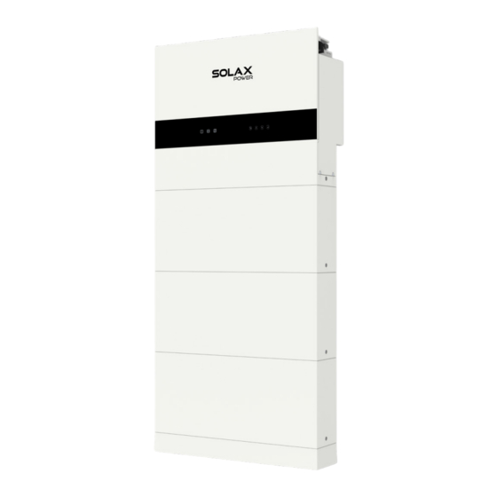
Page 17: Appearance
Product Overview Appearance LCD panel Upgrade / Dongle Button Type label Inverter electrical connection area Battery electrical Button , connection area switch Battery modules Base Figure 2-5 Apprearance Table 2-1 Desciption of appearance Item Description Type label clearly identifies the device type, serial number, specific Type label DC/AC parameters, certification, etc. -
Page 18: Dimensions
Product Overview Item Description USB port for upgrading and communication module connection. Upgrade/ Dongle Communication module includes a dongle/ 4G (optional) . Button Power on or off the inverter system. Inverter electrical Including battery terminals, AC terminals, communication terminals, connection area etc. - Page 19 Product Overview 150 mm 730 mm Figure 2-8 Battery module 75 mm 150 mm 730 mm Figure 2-9 Base 91.5 mm 167 mm 121 mm Figure 2-10 Series box...
-
Page 20: Control Panel And Indicators
Product Overview 2.3.2 Control Panel and Indicators Inverter Control Panel Timely output power Today’s energy Battery energy Power Today 0.0KWh Battery Normal Error indicator light Battery indicator light Down Status or error Operating indicator light Enter information Figure 2-11 Control Panel * The LCD screen in the whole passage is subject to the actual screen. - Page 21 Product Overview Table 2-3 Definition of keys Definition ESC key Exit from the current interface or function Up key Move the cursor to the upper part or increase the value Down key Move the cursor to the lower part or decrease the value Enter key Confirm the selection Battery Indicators...
- Page 22 Product Overview Status Description The status light comes on solid green light, and the state of SoC power Charging indicators depends on the actual situation. For details, please refer to the following “Figure 2-5 Indicator information while charging”. The status light comes on solid green light, and the state of SoC power Discharging indicators depends on the actual situation.
- Page 23 Product Overview Table 2-7 Indicators information while reporting errors Fault SoC1 SoC2 SoC3 SoC4 Huge differential pressure Flash Voltage fault (undervoltage and overvoltage of unit, overvoltage and undervoltage of total Flash voltage) Temperature fault (high temperature, low Flash Flash temperature) Current fault (overcurrent charging, Flash overcurrent discharging)
- Page 24 Product Overview Black Start The equipment can provide Black Start capacity, meaning that our energy storage inverter and battery can continue to run even if the power grid and photovoltaic panel are out of service. The startup procedure for Black Start is as follows: •...
-
Page 25: Ports Of Devices Of X3-Ies-A System
Product Overview 2.3.3 Ports of Devices of X3-IES-A System Ports of Inverter Right side Figure 2-13 Ports of an inverter Table 2-8 Description of ports Item Description C T/ Meter port: Connect a CT or a meter COM port: Connect communication cables USB port for upgrading and communication module connection Communication module includes dongle, 4G (optional) System button: Press to turn on or turn off the inverter system... -
Page 26: Item Description
Product Overview Ports of Battery (T-BAT-SYS) • HEAT Left side Right side Figure 2-14 Ports of a BMS Table 2-9 Description of ports Item Description The hot-plug interface connected to the inverter The hot-plug interface connected to the battery module BMS BUTTON: Start system BAT SWITCH: A switch for battery's input and output “DIP Switch”... - Page 27 Product Overview Item Description HEAT: Connect the HEAT port of the series box (if any), or a short-circuit plug must be inserted into the port NOTICE! The mark "*" indicates that when stacking the inverter onto the BMS, the inverterbattery grounding and communications are connected directly through the connector.
- Page 28 Product Overview • Battery module A hot-plug interface that is connected to the bottom of the battery module or the BMS. A hot-plug interface that is connected to the bottom of the battery module or the Base. Figure 2-16 Ports of a battery module •...
-
Page 29: Symbols On The Label And Devices Of X3-Ies-A System
Product Overview • Series box The series box shall be installed in case the battery modules purchased exceed 4 sets (including 4). Figure 2-18 Ports of a series box Table 2-10 Description of ports Item Description GND: Connect to the grounding port of the BMS. COM: Connect to the COM port of the BMS. - Page 30 Product Overview Symbol Description Danger of high voltages. Danger to life due to high voltages in the inverter! Danger. Risk of electric shock! The battery module may explode. Keep the battery system away from open flames or ignition systems. Keep the battery system away from children. Observe enclosed documentation.
-
Page 31: Working Principle
Product Overview Working Principle 2.4.1 Working Mode The inverter has two configurable working periods: allowed discharging period and forced charging period. For how to set the two working periods, please refer to “9.7 Settings” to set working modes. The default value of allowed discharging period is 00:00~23:59, and the default value of forced charging period is 00:00~00:00 (closed in default). - Page 32 Product Overview Self Use The self-use mode is suitable for areas with low feed- in subsidies and high electricity prices. The power of PV will supply the loads first, and surplus power will charge the battery, then the remaining power will feed into the grid. Priority: Loads >...
- Page 33 Product Overview Peak Shaving Mode (With Grid-tied Inverter) Peak Shaving mode is set for leveling out peaks in electricity use. System is controlled to charge up during off-peak hours and discharged during peak hours. Peak Shaving Mode Power (Assuming peak power from 7:00 to 9:00 and from 18:00 to 23:00) Idea: Leveling out peaks in electricity use.
- Page 34 Product Overview TOU mode In the TOU mode, different working modes, i.e Self-use, Charging, Discharging, Peaking shaving and Battery off can be set for different time periods in accordance with actual needs and environment conditions through SolaX Cloud App or Web. The day can be divided into up to 24 time slots, and the minimum time slot is 15 minutes, independent working mode can be set for each time slot.
-
Page 35: Circuit Diagram
Product Overview 2.4.2 Circuit Diagram The inverter unit converts DC into AC that meets the requirements of the power grid and feeds it into the power grid. The lightning arrester at AC / DC side can realize the function of surge protection. The principle design of inverter is shown in the figure below: DC BUS DC/AC DC/DC Fliter... - Page 36 Product Overview System Diagram B (applicable to most countries) Dongle Grid-tied inverter X3-IES-A BAT+BAT-BMS CT/Meter Breaker Main Breaker Grid T-BAT-SYS … Loads … Distribution Box N-BAR for loads Figure 2-23 System diagram with grid-tied inverter for most countries System Diagram C (applicable to Australia) Dongle X3-IES-A Breaker...
- Page 37 Product Overview NOTICE! The neutral wire is connected to the PE, and the diameter of the neutral wire must not be smaller than the diameter of the live wire. (Apply to Australia) System Diagram D (applicable to Australia) Dongle Grid-tied inverter X3-IES-A BAT+BAT-BMS CT/Meter...
-
Page 38: Transportation And Storage
Transportation and Storage If the devices of X3-IES-A system is not put into use immediately, the transportation and storage requirements needs to be met: Transportation • Observe the caution signs on the packaging of the devices before transportation. • Pay attention to the weight of the devices. Be cautious to avoid injury when carrying the devices. -
Page 39: Preparation Before Installation
Preparation before Installation Selection of Installation Location The installation location selected for the devices of X3-IES-A system is quite critical in the aspect of the guarantee of machine safety, service life and performance. • Flaunting an IP66 enclosure, the battery can be used outdoors and indoors. •... - Page 40 Preparation before Installation NOTICE! • For outdoor installation, precautions against direct sunlight, rain exposure and snow accumulation are recommended. • Exposure to direct sunlight raises the temperature inside the device. This temperature rise poses no safety risks, but may impact the device performance. •...
-
Page 41: Installation Options
Installation Options NOTICE! • X3-IES-A series inverter can match 2~6 battery modules. "Option A/ B/ C" is for one tower and "option D/ E/ F/ G" is for two towers. • Generally, up to three battery modules in one tower are recommended. Four battery modules in one tower can be selected when installation space is limited. - Page 42 Preparation before Installation Two Towers >300 mm >300 mm Option E Option D >300 mm >300 mm Option F Option G Figure 4-4 Installation options for two towers Table 4-1 Net weight and dimensions of components Option Option Option Option D Option E Option F Option G...
- Page 43 NOTICE! • The net weight of inverters of different powers differs. Please check the specific net weight of the X3-IES-A series inverter when calculating the total weight of the devices of X3-IES-A system. • Please consider the distance between the left tower and right tower under limited installation space.
-
Page 44: Installation Carrier Requirement
Preparation before Installation Table 4-6 Net weight and dimensions of T-BAT-SYS Battery Base Series box Cover module Length (mm) Width (mm) Height (mm) 91.5 Net weight (kg) 4.1.3 Installation Carrier Requirement The mounting location must be suitable for the weight and dimensions of the product and the support surface for installation must be made of a non-flammable material. -
Page 45: Clearance Requirement
Preparation before Installation 4.1.4 Clearance Requirement To guarantee proper heat dissipation and ease of disassembly, the minimum space around the inverter must meet the standards indicated below. • For installations with multiple devices, make sure to leave a minimum space of 300 mm between the left and right tower and 300 mm from the ceiling. -
Page 46: Tools Requirement
Preparation before Installation Tools Requirement Installation tools include but are not limited to the following recommended ones. If necessary, use other auxiliary tools on site. Measuring tape Utility knife Hammer drill Multimeter Flat-head Allen key Marker Cross screwdriver screwdriver Crimping tool Wire stripper Diagonal pliers for RJ45... -
Page 47: Additionally Required Materials
Preparation before Installation Additionally Required Materials Battery Table 4-7 Additionally required wires Required Material Type Diameter External diameter: over Corrugated pipe Protective pipe 67.2 mm Inverter Table 4-8 Additionally required wires Conductor Required Material Type Cross-section Communication Network cable CAT5E 0.2 mm²... -
Page 48: Unpacking And Inspection
Unpacking and Inspection The number of battery cartons will be different due to different modes of mounting. Therefore, please check whether the number of cartons received are correct before unpacking. For details, please refer to the following table. Table 5-1 Number of cartons One Tower Two Towers A BMS carton, and carton(s) of... - Page 49 Unpacking and Inspection Unpacking the BMS and battery module(s) according to the following figures. If there are other cartons, such as the base support carton, and series box carton, the unpacking pro- cedure can also be referred to the following figures. Figure 5-2 Unpacking the BMS Figure 5-3 Unpacking the battery module •...
-
Page 50: Scope Of Delivery
Unpacking and Inspection Scope of Delivery Inverter Inverter Brackets AC connector Waterproof connector M5*10 screws with a RJ45 Communication Expansion tubes RJ45 terminals M5*14 screws connector & ferrules Self-tapping screws RJ45 connector Cable shielding board Cable shielding board (General version) (Australia version) 6 mm²... - Page 51 Unpacking and Inspection Items Quantity Communication connector 1 pc Communication ferrules 16 pcs Waterproof connector with RJ45 1 pc M5*14 screws 6 pcs M5*10 screws 2 pcs Expansion tubes 2 pcs Self-tapping screws 2 pcs RJ45 terminals 3 pcs RJ45 connector 1 pc Cable shielding board 1 pc...
- Page 52 Unpacking and Inspection Expansion bolt Angle bracket M5*14 Phillips Tapping cheese head screw Adjustable bracket screw Base System performance Expansion screw label Document Rotation wrench Table 5-3 Packing list of BMS Item Quantity 1 pc Base 1 pc Angle brackets 4 pcs Adjustable brackets 4 pcs...
- Page 53 Unpacking and Inspection Battery Module M5*14 Phillips cheese Battery module head screw Document Table 5-4 Packing list of battery module Item Quantity Battery module 1 pc M5*14 Phillips cheese head screws 2 pcs Document Base Support (For wall mounting only) M5*20 Phillips countersunk head Expansion screw...
- Page 54 Unpacking and Inspection Series Box (For two towers only) Expansion bolt Angle bracket Series Box Tapping M5*14 Phillips cheese screw Adjustable bracket head screw Base Power cable (black) Communication cable Power cable (red) Expansion screw Grounding cable Heater cable Cover Document Table 5-6 Packing list of Series Box Item...
- Page 55 Unpacking and Inspection Cable (Optional) Positive power y cable Negative power y cable Female Phoenix Male Phoenix terminals (2000 mm) (2000 mm) terminals RNB14-5 ring terminals Table 5-7 Packing list of cables Item Quantity Positive power y cable (2000 mm) 1 pc Negative power y cable (2000 mm) 1 pc...
-
Page 56: Mechanical Installation
Mechanical Installation Mechanical Installation of X3-IES-A System Figure 6-1 Correct installtion angle NOTICE! • The wall selected for installation should be flat and perpendicular to the floor. The mechanical installation of the X3-IES-A system supports floor mounting and wall mounting. The two installation methods are illustrated below. Option B with three battery modules is taken as an example. - Page 57 Mechanical Installation WARNING! • Only the qulalified personel can perform the mechanical installation following the local standards and requirements. • Check the existing power cables or other piping in the wall to prevent electric shock or other damage. CAUTION! • Always be aware of the weight of the devices. Personal injuries may result if the devices are lifted improperly or dropped while being transported or mounted.
-
Page 58: Floor Mounting
Mechanical Installation Floor Mounting 6.2.1 One Tower for Floor Mounting NOTICE! • The mode of floor mounting is given priority for installation. • Take the installation procedure for Option B (three battery modules in one tower) as an example. Step 1: Remove dustproof covers from the base, battery module(s) and BMS before conducting installation. - Page 59 Mechanical Installation Step 3: Rotate the adjustment screws clockwise to ensure that it is even. Turn clockwise to lower the base, and turn anticlockwise to raise the base. Figure 6-5 Rotating adjustment screws NOTICE! • Use a spirit level to measure both side of the base to ensure that the base is even; •...
- Page 60 Mechanical Installation Step 5: Attach the angle bracket and adjustable bracket together by using M5*14 screws, but do not tighten them for a while. Figure 6-7 Attaching two brackets Step 6: Place the assembled bracket on the wall, align the hole to the hole on the battery module;...
- Page 61 Mechanical Installation Step 7: Remove the assembled bracket, and then drill two holes at a depth of more than 60 mm in the concrete wall by using a drill (Ø10 mm). Concrete Wall Ø10 mm Drill 90° > 60 mm Figure 6-9 Drilling holes NOTICE! •...
- Page 62 Mechanical Installation Tapping screw M5*14 8-10 N·m 2.2-2.5 N·m Figure 6-11 Securing the assembled bracket NOTICE! • If the base is shifted before securing assembled bracket, move it to its original location according to the mark previously drawn. Step 9: Place a battery module on the base. Figure 6-12 Placing the battery module NOTICE! •...
- Page 63 Mechanical Installation Step 10: Insert and tighten M5*14 screws on both sides (torque: 2.2-2.5 N·m). M5*14 2.2-2.5 N·m Figure 6-13 Tightening screws NOTICE! • Please make sure that the corners and edges of the base and battery module are aligned before tightening screws. Step 11: Place the second and third battery modules, and make sure that the corners and edges of the battery modules are aligned.
- Page 64 Mechanical Installation brackets on the wall; 3. Align the holes on the positioning cardboard with the dots in the second row on the wall; 4. Mark the dots where "X3-IES-A" is noted on the positioning cardboard. Figure 6-15 Attaching two brackets Figure 6-16 Marking the position of BMS Figure 6-17 Aligning the positioning cardboard with the dots on the wall...
- Page 65 Mechanical Installation Figure 6-18 Marking the position of the brackets of the inverter Step 13: Drill the holes for the BMS and the inverter and tighten them. 1. Remove the assembled brackets on the battery module, and then drill the four holes at a depth of more than 60 mm in the concrete wall by using a Drill (Ø10 mm);...
- Page 66 Mechanical Installation Figure 6-20 Knocking expansion tubes into the wall As for securing brackets, refer to Step 8. Figure 6-21 Tightening the BMS brackets NOTICE! • An electric drill dust collector is recommended. • To prevent dust from being released into the hot plug when drilling holes, users may use the package bag of the device or other materials to fully cover the battery module.
- Page 67 Mechanical Installation Step 14: Place the BMS, and then tighten the M5*14 screws on both sides (torque: 2.2-2.5 N·m) Figure 6-22 Placing the BMS M5*14 2.2-2.5 N·m Figure 6-23 Tightening M5 screws NOTICE! • Please make sure that the corners and edges of the BMS and battery module are aligned before tightening screws.
- Page 68 Mechanical Installation Step 15: (For Australia version only) Install the anti-tamper bracket. M4*10 1.2±0.1 N·m Figure 6-24 Install the anti-tamper bracket Step 16: Remove the dustproof cover from the bottom of the inverter. Figure 6-25 Removing the dustproof cover...
- Page 69 Mechanical Installation Step 17: Install the inverter on the BMS. Figure 6-26 Installing the inverter NOTICE! • At least two persons are required to move the inverter. Step 18: Lock the screws on both sides of the inverter with the BMS. M5 * 14 2±0.1 N·m Figure 6-27 Locking the inverter with the BMS...
- Page 70 Mechanical Installation Step 19: Lock the inverter brackets on both sides of the inverter. 1. Tighten but not lock the self-tapping screws into the wall. 2. Lock screws on the inverter. 3. Lock screws into the wall. ST 6.3 2±0.1 N·m M5 * 10 2±0.1 N·m Figure 6-28 Locking the inverter brackets...
-
Page 71: Two Towers For Floor Mounting
Mechanical Installation 6.2.2 Two Towers for Floor Mounting NOTICE! • Take the installation procedure for option G as an example. Step 1: As for the installation steps for the following figure, please refer to the installation procedure for “6.2.1 One Tower for Floor Mounting” (Steps 1 to 20) for the left tower and the “6.2.1 One Tower for Floor Mounting”... -
Page 72: Wall Mounting
Mechanical Installation Wall Mounting 6.3.1 One Tower for Wall Mounting NOTICE! • Take the installation procedure for three battery modules as an example. Step 1: Remove dust covers from the base, battery module(s) and BMS before conducting installation. Base Battery module Figure 6-31 Removing dust covers Step 2: Tighten M5*8 screws on both sides to attach the base support and transverse plate together (torque: 2.2-2.5 N·m). - Page 73 Mechanical Installation Step 3: Place the assembled base support and transverse plate on the wall, check the cylindrical plastic bubble spirit level on the transverse plate. If the bubble isn't in the centre, slightly bow it to the horizontal. Then circle along the inner ring of the four holes. cylindrical plastic bubble...
- Page 74 Mechanical Installation Step 5: Place the assembled base support and transverse plate on the wall again, and check whether the bubble is in the centre. Attach the expansion screws to such four holes, hit it by using rubber mallet, and then tighten it by using torque wrench (torque: 20-25 N·m) 20-25 N·m Figure 6-35 Tightening expansion screws...
- Page 75 Mechanical Installation Step 7: Place the battery module on the base. Figure 6-37 Placing battery module NOTICE! • At least two persons are required to move the battery module. • Please ensure that the side with "R" shall be against the wall. Step 8: Insert and tighten M5*14 screws on both sides (torque: 2.2-2.5 N·m).
- Page 76 Mechanical Installation Step 9: Place the second and third battery modules, and make sure that the corners and edges of the battery modules are aligned. Step 8 Steps 7 to 8 Figure 6-39 Placing battery modules Step 10: Locate the position of the BMS and the inverter. 1.
- Page 77 Mechanical Installation Figure 6-41 Marking the position of BMS Figure 6-42 Aligning the positioning cardboard with the dots on the wall Figure 6-43 Marking the position of the brackets of the inverter...
- Page 78 Mechanical Installation Step 11: Drill the holes for the BMS and the inverter and tighten them. 1. Remove the assembled brackets on the battery module, and then drill the four holes at a depth of more than 60 mm in the concrete wall by using a drill (Ø10 mm);...
- Page 79 Mechanical Installation 8-10 N·m Tapping screw M5*14 2.2-2.5 N·m Figure 6-46 Securing the assembled bracket NOTICE! • An electric drill dust collector is recommended. • To prevent dust from being released into the hot plug when drilling holes, users may use the package bag of the device or other materials to fully cover the battery module.
- Page 80 Mechanical Installation M5*14 2.2-2.5 N·m Figure 6-48 Tightening M5 screws NOTICE! • Please make sure that the corners and edges of the BMS and battery modules are aligned before tightening screws. Step 13: (For Australia version only) Install the anti-tamper bracket. M4*10 1.2±0.1 N·m Figure 6-49 Install the anti-tamper bracket...
- Page 81 Mechanical Installation Step 14: Remove the dustproof cover from the bottom of the inverter. Figure 6-50 Removing the dustproof cover Step 15: Install the inverter on the BMS. Figure 6-51 Installing the inverter NOTICE! • At least two persons are required to move the inverter.
- Page 82 Mechanical Installation Step 16: Lock the screws on both sides of the inverter with the BMS. M5 * 14 2±0.1 N·m Figure 6-52 Locking the inverter with the BMS Step 17: Lock the inverter brackets on both sides of the inverter. 1.
-
Page 83: Two Towers For Wall Mounting
Mechanical Installation 6.3.2 Two Towers for Wall Mounting NOTICE! • Take the installation procedure for six battery modules as an example. Step 1: As for the installation steps for the following figure, please refer to the installation procedure for “6.3.1 One Tower for Wall Mounting” (Steps 1 to 18) for the installation procedure for the left tower and the “6.3.1 One Tower for Wall... -
Page 84: Battery Capacity Expansion
Mechanical Installation Step 2: Place the series box, insert and tighten M5*14 screws, with totalling 4 screws (torque: 2.2-2.5 N·m). M5 * 14 2.2-2.5 N·m Figure 6-55 Placing the series box NOTICE! • The side of the series box with "R" shall be against the wall. •... -
Page 85: Electrical Connection
Electrical Connection Electrical Connection of Battery 7.1.1 Details of Cables Communication cable: There are two terminals at both ends. One connects to the COM port of the BMS, and the other connects to the COM port of the series box. Figure 7-1 Communication cable Heater cable: There are two terminals at both ends. -
Page 86: Wiring Procedure
Electrical Connection NOTICE! • The above-mentioned cables are delivered with the Accessories of Series Box. 7.1.2 Wiring Procedure WARNING! • Only the qualified personnel can perform the wiring. • Follow this manual to wire connection. The device damage caused by incorrect wiring is not in the scope of warranty. - Page 87 Electrical Connection Step 1: Before conducting wiring between the BMS and series box, press and hold the lock button to unplug the short power cable. HEAT Short power cable HEAT Lock button Figure 7-6 Removing short power cable Step 2: Rotate the waterproof cap anti-clockwise to remove it. And rotate the short- circuit plug anti-clockwise.
- Page 88 Electrical Connection HEAT port short-circuit plug Figure 7-8 Closing short-circuit plug NOTICE! • Press and hold the lock button while unplugging the power cable, or it cannot be pulled out. • Don't violently remove the short-circuit plug before the arrow on the rotating ring is aligned with the arrow on the panel.
- Page 89 Electrical Connection Step 3: Connect B+ of the BMS to B+ of the series box; Connect B- of the BMS to B- of the series box; Connect COM port of the BMS to COM port of the series box; Connect HEAT port of the BMS to HEAT port of the series box; Connect the grounding port of the BMS to the grounding port of the series box.
- Page 90 Electrical Connection Step 4: Pull cables through pipes after connecting cables to the BMS. Pull the power cable (red) and heater cable through pipe 1, and pull the power cable (black), communication cable and grounding cable through pipe 2. Pipe 2 Pipe 1 Figure 7-10 Pulling cables NOTICE!
- Page 91 Electrical Connection Step 6: Firstly rotate the rotating ring until the arrow on it is aligned with the arrow on the panel before removing the short-circuit plug, and then insert the heater cable into the HEAT port and rotate clockwise to close it. Align the groove according to the arrows...
-
Page 92: Installation Of Cover
Electrical Connection 7.1.3 Installation of Cover After finishing wiring, push the cover to the series box, and tighten M5*14 screws on both sides to secure the cover (torque: 2.2-2.5 N·m). M5*14 2.2-2.5 N·m Figure 7-13 Tightening M5 screws NOTICE! • Please make sure that the corners and edges of the cover and battery modules are aligned before tightening screws. -
Page 93: Electrical Connection Of Inverter
Electrical Connection Electrical Connection of Inverter DANGER! • Before electrical connection, make sure the DC switch of the battery (T-BAT-SYS), the inverter AC breaker are turned off. Otherwise, an electrical shock may be caused by high voltage, resulting in serious personal injury or death. WARNING! •... -
Page 94: Grid Connection
Electrical Connection 7.2.2 Grid Connection NOTICE! • Before connecting the inverter to the grid, approval must be received by the local utility as required by national and state interconnection regulations. Requirements for AC Side Connection • Grid Voltage requirement » The grid voltage must be within the permissible range. - Page 95 Electrical Connection Step 1: Prepare a Grid cable (five-core wire) and strip the insulation jacket as below. wire cutter 65~72 mm wire stripper Figure 7-16 Striping the Grid cables Step 2: Insert L1, L2, L3 and PE wires of the Grid cables into ferrules. Use a crimping tool for ferrules to crimp the ferrules.
- Page 96 Electrical Connection Figure 7-19 Cutting the round membrane NOTICE! • If only one round hole is needed, please do not cut the other round membrane, to ensure the sealing of the inverter. » According to the outer diameters of the cable, take out the corresponding sealing plug with your hand.
- Page 97 Electrical Connection Step 4: Connect Grid cables to the AC connector. » Thread the Grid cables through the swivel nut, cable support sleeve, and the enclosure separately. Insert the crimped conductors L1, L2, L3, N, and PE into the corresponding position of the rubber core and tighten them. Figure 7-22 Inserting Grid cables into the AC connector »...
- Page 98 Electrical Connection Figure 7-25 Pulling up the latch Step 7: Remove the dustproof cover on the Grid & EPS port of the inverter. Figure 7-26 Removing the dustproof cover Step 8: Plug the AC connector into the Grid & EPS port of the inverter and lock the AC connector with an Allen key.
-
Page 99: Communication Connection
Electrical Connection 7.2.3 Communication Connection COM and CT/Meter ports are for the communication function of the inverter. Communication Port Introduction Table 7-1 Description of COM Icon Definition Function Comment PARALLE_SYNC1 PARALLE_SYNC2 EPSBOX_RELAY_VCC PARALLE485A Parallel signal out- PARALLE485B GND_COM Parallel signal port CAN_L (RJ45) CAN_H... - Page 100 Electrical Connection Icon Definition Function Comment Parallel signal port CAN_L Parallel signal input (RJ45) CAN_H DRM1/5 DRM2/6 Logical interface is DRM3/7 Logic interface for Australia (AS4777) signal DRM4/8 and other standards REF GEN/0 COM/DRM0 RS485 differential communication with remote 485A signal-A SolaX's datahub, EV-Charger and oth-...
- Page 101 Electrical Connection DRM Connection (COM Port)(Applicable to AS/NZS 4777) According to Australia AS/NZS 4777, the inverter need to support the function of demand response mode (DRM), DRM 0, DRM 1 and DRM 5 are available now. Table 7-2 Desciptions of DRM Mode Requirement DRM 0...
- Page 102 Also the external equipment can be controlled through COM communication. External Connection with a Datahub Pin Assignment Table 7-3 Inverter connected with a SolaX datahub COM port of X3-IES-A series inverter RS485-1/-2/-3/-4 port of SolaX datahub Pin definition Pin definition 7 (P3)
- Page 103 Electrical Connection External Connection with an EV Charger Pin Assignment Table 7-4 Inverter connected with an SolaX EV Charger COM port of X3-IES-A series inverter COM port of SolaX EV Charger Pin definition Pin definition 7 (P3) remote 485A 8 (P3)
- Page 104 Electrical Connection External Connection with an Adapter Box G2 Pin Assignment Table 7-5 Inverter connected with an SolaX adapter box G2 COM port of X3-IES-A series inverter 485_INV port of SolaX Adapter Box G2 Pin definition Pin definition 7 (P3)
- Page 105 Electrical Connection Wiring Procedures Figure 7-32 Well connected COM port Step 1: Loosen the swivel nut and pull out the rubber stoppers inside. Press the bricks on the terminal block and pull the block out. terminal block rubber stopper Figure 7-33 Disassembling the communication connector Step 2: Thread two communication cables through the swivel nut and the communication connector.
- Page 106 Electrical Connection Step 3: Crimp the stripped end with RJ45 terminals with a crimping tool for RJ45. Crimping tool for RJ45 Figure 7-35 Crimping terminals Step 4: Strip communication cables as needed as below. wire stripper Figure 7-36 Stripping cables Step 5: Thread communication cables through the swivel nut and the communication connector.
- Page 107 Electrical Connection Step 6: Crimp ferrules and plug well crimped wires into the terminal block as needed. crimping tool for ferrules Figure 7-38 Crimping ferrules Step 7: Insert the terminal block connected with cables into the communication connector until there is an audible click. Screw the swivel nut tightly. Click! Figure 7-39 Inserting the terminal block into the connector NOTICE!
- Page 108 Electrical Connection CT/Meter Connection (CT/Meter Port) This section only introduces the wiring of the CT/Meter port of the inverter. For wiring procedures of the CT and meter side, see “14.1 CT/Meter Connection Scenarios”. CAUTION! • Compatible meters and CTs must be properly connected to the inverter, otherwise, the inverter will shut down and prompt a Meter Fault alarm.
- Page 109 Electrical Connection Step 2: Thread the communication cable through the waterproof connector. Figure 7-42 Threading the communication cable Step 3: Strip and crimp the communication cable. » For CT connection a. Strip around 15 mm wire insulation off both ends of the cable. Figure 7-43 Stripping the communication cable for CT b.
- Page 110 Electrical Connection Table 7-7 Pin number and color PIN No. Color PIN No. Color Orange-White Blue-White 1 2 3 4 5 6 7 8 Orange Green Green-White Brown-White Blue Brown » For meter connection a. Strip around 15 mm wire insulation off one end of the communication cable.
- Page 111 Electrical Connection Step 4: Remove the dustproof cover from the CT/Meter port of the inverter, insert the RJ45 terminal into the port, and then secure the waterproof connector. An audible "Click" will be heard if it is successfully connected. Figure 7-47 Connecting cable to the CT/Meter port NOTICE! •...
- Page 112 Electrical Connection Figure 7-49 Locking the board well » (For Australia version only) Hang the cable shielding board on the screws on the inverter and lock the screws at the bottom of the inverter. Install the padlock. (The lock rod 's diameter doesn't exceed 5 mm.) M5*14 2±0.1 N·m cross...
-
Page 113: Monitoring Connection (Upgrade/ Port)
Electrical Connection Figure 7-52 Installing the padlock 7.2.4 Monitoring Connection (UPGRADE/ Port) The inverter provides a DONGLE terminal, which can transmit data of the inverter to the monitoring website via the WiFi+LAN dongle or WiFi+4G (optional). The WiFi+Lan dongle is equipped with 2 kinds of communication modes (WiFi mode or LAN mode). NOTICE! WiFi dongle •... - Page 114 Electrical Connection Monitoring Connection Diagram Cloud Router Figure 7-53 WiFi mode connection diagram Cloud Router Figure 7-54 LAN mode connection diagram Cloud Figure 7-55 WiFi+4G connection diagram...
- Page 115 Electrical Connection Wiring Procedures WiFi mode: » Assemble the dongle; M2.5 0.8±0.1 N·m Figure 7-56 Assembling the dongle » Plug the dongle to the inverter. Figure 7-57 WiFi connection procedure CAUTION! • The buckles must be on the same side. Otherwise, the dongle may be damaged. NOTICE! •...
- Page 116 Electrical Connection Figure 7-58 Disassembling the waterproof connector » Assemble the dongle. M2.5 0.8±0.1 N·m Figure 7-59 Assembling the LAN dongle » Plug the dongle to the inverter. For network configuration of the dongle, see “10 Operation on SolaX App and Web”.
- Page 117 Electrical Connection Ø6 drill Depth: >50 mm 0.8±0.1 N·m Figure 7-61 Mounting the WiFi stand c. Plug the dongle into the WiFi connecting cable. Figure 7-62 Plugging the dogle...
-
Page 118: System Commissioning
System Commissioning Checking before Power-on Make sure that the device installed correctly and securely; Make sure that the system BUTTON on the inverter and the AC breakers connected to the inverter are OFF. Make sure that all the BMS BUTTON and BAT SWITCH are OFF; Make sure that all Grid cables are connected correctly and securely;... -
Page 119: Powering On The System
System Commissioning Powering on the System Step 1: Turn on the AC breaker and check whether the LCD screen lights on. If the LCD screen is not on, turn off the AC breaker and check whether the Grid cable is conected correctly and securely. - Page 120 System Commissioning Step 3: Turn on the inverter system BUTTON. Figure 8-3 Pressing the inverter button NOTICE! • The button is in OFF status by default. • A system problem may be encountered while pressing the button frequently. The user may need to wait at least 10 seconds and then try again. Step 4: Check whether the current “Safety Code”...
-
Page 121: Checking After Power-On
System Commissioning NOTICE! • When the meter or CT is correctly connected, the CT/Meter power displays on the CT/Meter check interface; when the connection method is wrong, "Meter Fault" displays on this interface. Checking after Power-on Check whether the inverter has any abnormal noise. Check whether the indicator lights report an error and whether the LCD screen displays the error message. -
Page 122: Operation On Lcd
Operation on LCD Overview of LCD Press Up and Down to select the setting item and press Enter to confirm it. If there is no operation on the inverter's LCD screen for 10 minutes, it will go black. Press any key to illuminate the screen again. The main interface is the default interface, the inverter will automatically return to this interface when the system starts successfully or does not operate for a period of time. - Page 123 Operation on LCD • “System Status” Battery System Status On-grid Meter/CT Figure 9-4 System status diagram • “History Data” On-grid E_Feedin History Data Error Log Figure 9-5 History data diagram • Setting User Setting and Advance Setting are included in Setting. Here below display the specific items under the two settings.
-
Page 124: System On/Off
Operation on LCD • “About” Inverter About Battery Internal code Figure 9-8 About diagram NOTICE! Property losses or system damage due to unauthorized access to the system when the keys on the LCD are mistakenly pressed. • System ON/OFF, Work Mode can be set and System Status, Parallel Status, History Data and About can be browsed without any password. -
Page 125: Work Mode
Operation on LCD Work Mode Setting path: Menu > Work Mode You can select a specific work mode to decide the working principle of the inverter in this interface. Setting Work Mode After entering the Work Mode interface, you can select Self Use, Feed-in Priority, Manual, Peak Shaving and TOU Mode as follows. -
Page 126: System Status
Operation on LCD working mode is Peak Shaving, it displays as follows. ======TOU====== ======TOU====== >Current Mode: PeakLimits: Peak Shaving Figure 9-13 Displaying the current work mode in TOU Mode interface System Status Displaying path: Menu > System Status Displaying System Status After entering the System Status interface, the status of Battery, On-grid and Meter/CT as follows. -
Page 127: History Data
Operation on LCD =====Meter/CT===== =====Meter/CT===== ====System Status==== >Pfeedin A >P_USERDEF A >Meter/CT Pfeedin B P_USERDEF B Pfeedin C P_USERDEF C Figure 9-16 Displaying Meter/CT status History Data Displaying path: Menu > History Data Displaying History Data After entering the History Data interface, the status of On-grid, E_Feedin and Error Log as follows. -
Page 128: Settings
Operation on LCD » Error Log Here display error logs of the device. The default status is "No Error". =====Error Log===== No Error Figure 9-19 Displaying Error Log Settings Setting path: Menu > Settings Enter the Settings interface and input the default password "0000" to enter the User setting interface. - Page 129 Operation on LCD ====Date & Time==== > 2023 - 07 - 06 10:05 Figure 9-21 Setting the system date and time Setting Language This inverter provides multiple languages for customers to choose, such as English, Deutsch, francais, Polskie, Espanol, Português and Italiano. Select Language in the User Setting interface, press Enter to enter the Language interface.
- Page 130 Operation on LCD Setting Feed-in Priority » Setting Min SoC Min SoC means the minimum battery SoC, and the battery won't discharge power when the actual battery SoC reaches this value. Default Min SoC: 10% ; range: 10%~100%. ====Feedin Priority==== Min SoC Figure 9-25 Setting Min SoC »...
- Page 131 Operation on LCD ===Char&Disc Period=== ==Char&Disc Period2== Function Control >Char&Disc Period2 > Enable < ==Char&Disc Period2== ==Char&Disc Period2== >Forced Charg Period >Forced Charg Period Start Time End Time 00:00 00:00 ==Char&Disc Period2== ==Char&Disc Period2== >Allowed Disc Period >Allowed Disc Period Start Time End Time 00:00...
- Page 132 Operation on LCD PeakLimits2 is set to limit the power that loads charge from the grid. Once the power of loads exceeds PeakLimits2 during DischgPeriod2, the battery discharge power for loads. ==Peak shaving mode== ====DisChgPeriod2==== >DisChgPeriod2 ShavingStartTime ChargeFromGrid > 19:00 <...
-
Page 133: Advance Setting
Operation on LCD Setting User Password You can reset the password in the User Password interface. Default user password: 0000. ===User Password=== ===User Password=== ===User Password=== Set OK! Setting failed! Figure 9-33 Resetting User Password 9.6.2 Advance Setting Setting path: Menu > Setting > Password > Advance Setting Only professional installers can modify the items (refer to “Figure 9-7 Advance setting diagram”) in the Advance Setting interface under the permission of SolaX company. - Page 134 Operation on LCD NOTICE! • For the Australian, please select Australian Region A/B/C in complicance with AS/ NZS 4777.2:2020. Only after the safety code setting is completed, some designated parameters in the inverter system will take effect according to the corresponding safety regulations.
- Page 135 Operation on LCD Region Australia A Australia B Australia C Zealand Standarad AS4777_2022 AS4777_2022 AS4777_2022 Setting Code Zealand Range Name UN-G-F1 47 Hz 47 Hz 45 Hz 45 Hz 40-50 Hz UNGF1-T 1.5 s 1.5 s 1.5 s UN-G-F2 47 Hz 47 Hz 45 Hz 45 Hz...
- Page 136 Operation on LCD ======Charger====== ======Charger====== >Max Charge Charger upper limit Current: 100% Figure 9-36 Setting battery charging and discharging limits Setting Export Control If Necessary This function allows the inverter to control the output power to the grid. The user value set must be less than the maximum value.
- Page 137 Operation on LCD • Setting the Export Control under Other Safety Codes » Set the Safety Code (refer to “Safety Code” for details) » Select Export Control in Advance Settings and set the User Value you needed. For the countries with zero export controllimit, set the user value to "0".
- Page 138 Operation on LCD ====External ATS==== Function Control > Enable < Figure 9-42 Enabling/disabling external ATS Setting Power Factor (applicable to the local grid requirements of a specific country) The items in the Power Factor interface will be adjusted in accordance with the local safety requirements and law regulations, casual modification is prohibited.
- Page 139 Operation on LCD Mode Select Items SetQuPower1 SetQuPower2 SetQuPower3 SetQuPower4 QuRespondV1 QuRespondV2 Q(u) QuRespondV3 QuRespondV4 3Tau QuDelayTimer QuLockEn Fixed Q Power Q Power In the Q(u) interface, when QuLockEn is selected, the following items need to be set. ====QuLockSetting==== ====QuLockSetting==== ====QuLockSetting==== QuLockIn QuLockOut...
- Page 140 Operation on LCD Items ResponseV1 ResponseV2 ResponseV3 ResponseV4 3Tau Pu Functiion SetPuPower1 SetPuPower2 SetPuPower3 SetPuPower4 3Tau_Charge Pu Type Setting FVRT Function (apply to 50549) The items in the FVRT interface will be adjusted in accordance with the local safety requirements and law regulations, casual modification is prohibited. Default VacUpper: 265 V Default VacLower: 115 V The default parameters adjust with the...
- Page 141 Operation on LCD value is shown in curve A. For TOR, the curve cos φ = f(P) should be curve B. The set default value is shown in curve B. For CEI 0-21, the default value of PFLockInPoint is 1.05. When Vac> 1.05Vn, Pac>...
- Page 142 Operation on LCD • Reactive power control, reactive power standard curve Q= f(V). V2s=1.10Vn V1s=1.08Vn=QuVlowRate Qmax V2i=0.90Vn V2i=0.92Vn=QuVlowRate -Qmax Figure 9-51 Curve Q=f(V) Setting DRM Function (applied to NZS4777.2) The DRM function is a demand response method required by the NZS4777.2 standard and is only applicable to NZS4777.2.
- Page 143 Operation on LCD NOTICE! • Refer to section “7.2.3 Communication Connection” for specific parallel connection diagram. NOTICE! • Master inverter has an absolute lead in the parallel system to control all slave inverter’s energy management and dispatch control. Once master inverter has some error and stop working, all slave inverter will be stop simultaneously.
- Page 144 Operation on LCD NOTICE! • If a slave inverter is set to Free mode but not disconnect the network cable, this inverter will return to Slave mode automatically. • If a slave inverter is disconnected with other inverter but not be set to Free mode, this inverter will stop working and maintain waiting status.
- Page 145 Operation on LCD Setting Phase Unbalanced This function controls the distribution of AC output power. Enable means each phase will be divided according to the loads connected with each phase. Disable means each phase power will be divided equally. Disable is the default setting.
- Page 146 Operation on LCD Setting ExternalGen ExternalGen is set for controlling the generator connected. • Set Enable/Disable in the ExternalGen interface. The following settings display when Disable is set. ====ExternalGen==== Function Control > Disable < Figure 9-62 Enabling/ disabling ExternalATS function Max Charge Power to be set in the interface must meet the following two conditions when the maximum charging power of batteries is to be set.
- Page 147 Operation on LCD » Setting Char&Disc period2 ====ExternalGen==== ====ExternalGen==== Forced Charg Period Char&Disc Period2 Start Time > Enable < 00:00 ====ExternalGen==== ====ExternalGen==== Allowed Disc Period Forced Charg Period Start Time End Time 00:00 00:00 ====ExternalGen==== Allowed Disc Period End Time 00:00 Figure 9-65 Setting Char&Disc period2 »...
- Page 148 Operation on LCD » Setting MaxRunTime, MinRestTime, Allow Work ====ExternalGen==== ====ExternalGen==== MaxRunTime MinRestTime 0 Min 0 Min ====ExternalGen==== ====ExternalGen==== Allow Work Allow Work start time end time 00:00 00:00 Figure 9-69 Setting MaxRunTime, MinRestTime, allow working period » Setting Char&Disc period ====ExternalGen==== ====ExternalGen==== Forced Charg Period...
- Page 149 Operation on LCD Setting Reset You can set Reset Error Log, Reset Meter/CT, Reset INV Energy. Reset Wifi, Factory Reset in the Reset interface. » Reset Error Log ======Reset====== ===Reset Error Log=== >Reset Error Log Reset Reset Meter/CT > No < Reset INV Energy Figure 9-73 Resetting Error Log »...
- Page 150 Operation on LCD ===Battery Heating=== ===Battery Heating=== Heating Period 1 Func Select: Start Time > Enable < 00:00 ===Battery Heating=== ===Battery Heating=== Heating Period 2 Heating Period 1 Start Time End Time 00:00 00:00 ===Battery Heating=== Heating Period 2 End Time 00:00 Figure 9-78 Enabling battery heating and setting working periods Setting Extended BAT FUNC...
- Page 151 Operation on LCD =====Pgrid Bias===== =====Pgrid Bias===== =====Pgrid Bias===== Pgrid Bias Pgrid Bias Pgrid Bias > Disable < > Grid < > INV < Figure 9-81 Setting the Pgrid bias Setting Internal485 Here items in Internal485 interface can be set to achieve communication with SolaX devices.
-
Page 152: About
Operation on LCD Setting Battery Charge EVC You can set Enable/Disable to control whether the battery can discharge energy to an EV Charger. Enable: the battery can discharge energy to an EV Charger. Disable: the battery cannot discharge energy to an EV Charger. ==Battery charge EVC== Function Control >... - Page 153 Operation on LCD Displaying Battery Information You can view battery cell brand, BMS SN, Slave 1 SN, Slave 2 SN, Slave 3 SN, Slave 4 SN, BMS FW version and slave FW version in the Battery interface. =======About======= Inverter ======Battery====== >Battery BatBrand: BAK Internal Code...
-
Page 154: 10 Operation On Solax App And Web
10 Operation on SolaX App and Web 10.7.1 Downloading and Installing App Select and scan the QR code below to download SolaxCloud APP. You can also find the QR codes at the top left of the login page of www.solaxcloud.com or on the user manual of Pocket series communication module. -
Page 155: 11 Troubleshooting And Maintenance
11 Troubleshooting and Maintenance Before troubleshooting or maintenance operation, please ensure the system has been powered off (refer to “8.4 Power off” for specific steps). 11.1 Troubleshooting This section contains information and procedures for resolving possible problems with the inverter and the rechargeable battery, and provides the troubleshooting tips to identify and solve most problems that may occur. - Page 156 Troubleshooting and Maintenance Error Code Fault Descriptions and Diagnosis Battery voltage fault • Check battery input voltage if it's within normal IE 07 Bat Volt Fault range • Or ask the installer for help. Grid voltage out of range in the last 10 minutes •...
- Page 157 Troubleshooting and Maintenance Error Code Fault Descriptions and Diagnosis External fault of BMS . Unable to establish communication with inverter. IE 19 BMS Lost • Restart the BMS. • Contact the after-sales personnel of our company. Low temperature fault. • Check if the ambient temperature is too low. IE 21 Low Temp Fault •...
- Page 158 Troubleshooting and Maintenance Error Code Fault Descriptions and Diagnosis Power type fault • Upgrade the software and press the ESC" key to IE 101 Power Type Fault restart the inverter. • Or ask for help from the installer if it can not return to normal.
- Page 159 Troubleshooting and Maintenance Error Code Fault Descriptions and Diagnosis Battery Error - External Communication Fault BE 01 BMS_ExterErr • Please contact the battery supplier. Internal fault of BMS. Unable to establish communication among battery modules. BE 02 BMS_InterErr • Restart the BMS. •...
- Page 160 Troubleshooting and Maintenance Error Code Fault Descriptions and Diagnosis Voltage sampling fault of the BMS. BE 13 BMS_VolSen • Restart the BMS. • Contact the after-sales personnel of our company. Temperature sensor failure BE 14 BMS_TempSen • Restart the battery. •...
- Page 161 Troubleshooting and Maintenance Error Code Fault Descriptions and Diagnosis BMS temperature varies greatly. BE 26 BMS Tempdiff • Restart the BMS. • Contact the after-sales personnel of our company. BMS sampling fault. BE 27 BMS_BreakFault • Restart the BMS. • Contact the after-sales personnel of our company. Battery hardware protection failure BE 28 BMS_FlashFault...
-
Page 162: Maintenance
Troubleshooting and Maintenance 11.2 Maintenance Regular maintenance is required for the devices. The table of “Proposal of Maintenance” below lists the operational maintenance for expressing the optimum device performance. More frequent maintenance service is needed in the worse work environment. Please make records of the maintenance. - Page 163 Troubleshooting and Maintenance Battery Maintenance Precautions • If the ambient temperature for storage is between 30°C and 50°C (86°F to 122°F), please recharge the battery modules at least once every 6 months. • If the ambient temperature for storage is between -20°C and 30°C (-4°F to 86°F), please recharge the battery modules at least once every 12 months.
-
Page 164: Upgrading Firmware
Troubleshooting and Maintenance 11.2.2 Upgrading Firmware Upgrade Precautions WARNING! • If the DSP and ARM firmware need to be upgraded, please note that ARM firmware must be upgraded first, then DSP firmware! • Please make sure that the category format is correct, do not modify the firmware file name. - Page 165 Troubleshooting and Maintenance Upgrade Steps Please save the Upgrade firmware in your U disk first. Find the Upgrade port of the inverter, unplug the monitoring module (dongle / 4G ) by hand, and insert the USB flash drive. (Refer to “7.2.4 Monitoring Connection (UPGRADE/ Port)”...
-
Page 166: 12 Decommissioning
• When disassembling the X3-IES-A system, strictly follow the steps as below. • Only use measuring devices with a DC input voltage range of 600 V or higher. Disassembling X3-IES-A Series Inverter Step 1: Press the buttons on the inverter and the battery to shut down the system. - Page 167 Decommissioning Step 3: Turn off the AC breaker between the inverter and the power grid. Step 4: Turn off the breakers between the inverter and the power grid. Step 5: Wait for at least 5 minutes to fully discharge the capacitors inside the inverter. Step 6: Disassemble the AC connector and disconnect the Grid cable.
- Page 168 Decommissioning Unplug the AC connector together with the Grid cables from the inverter. Figure 12-5 Unplugging the AC connector Unscrew the swivel nut of the AC connector, and then pull out the rubber sealing stopper. Insert the disassembling tool into the terminal block inside the AC connector, press and hold the double arc edges of the tool, push the Grid cables forward to poke the terminal block out from the connector, and then disconnect the cables.
- Page 169 Decommissioning Step 7: Press the clips on both sides of the communication connector and pull the communication connector outward to disconnect the Communication cable. Figure 12-7 Disconnecting the communication connector Step 8: Loosen the swivel nut and disconnect the CT/Meter cable. Figure 12-8 Disconnecting the CT/Meter cable Step 9: Disconnect the WiFi .
- Page 170 Decommissioning Step 10: Put the original protective cap on the terminals. Step 11: Unscrew the screws of fastening the wall mounting bracket and remove the wall mounting bracket. Disassembling T-BAT-SYS-HV-S50E Battery System Step 12: Press and hold the lock button on the terminals to unplug the short power cable in the case of one tower;...
-
Page 171: Packing The Devices Of X3-Ies-A System
Decommissioning NOTICE! • The above steps for disconnecting cables apply to both the BMS and series box. 12.2 Packing the Devices of X3-IES-A System • Load the inverter, the devices of battery system into the original packing material if possible. •... -
Page 172: 13 Technical Data
13 Technical Data • Inverter AC Output Model X3-IES-5K-A X3-IES-10K-A X3-IES-15K-A 5000 10000 15000 Norminal AC power [VA] (4999 for AS4777) (9999 for AS4777) (14999 for AS4777) 5500 10000 16500 Max. apparent AC power [VA] (4999 for AS4777) (9999 for AS4777) (14999 for AS4777) Max. - Page 173 Technical Data Battery Model X3-IES-5K-A X3-IES-10K-A X3-IES-15K-A Battery voltage range [V] 160-800 Recommended battery voltage [V] Max.charge/discharge current [A] Battery connection Communication interfaces CAN/RS485 Efficiency, Power Consumption, Protection and Standard Model X3-IES-5K-A X3-IES-10K-A X3-IES-15K-A Rated battery charge/discharge efficiency 97.6% / 97.4% Internal consumption (night) [W] <5 Idle mode...
- Page 174 Technical Data • Battery Configuration List Nominal Energy Operating Model Battery Module (kWh) Voltage (Vdc) T-BAT HS 5 TBMS-MCS0800E × 1 TP-HS50E × 1 90-116 T-BAT HS 10 TBMS-MCS0800E × 1 TP-HS50E × 2 10.2 180-232 T-BAT HS 15 TBMS-MCS0800E × 1 TP-HS50E ×...
- Page 175 Technical Data NOTICE! 1. Test conditions: 25°C, 100%, depth of discharge (DoD), 0.2C charge & discharge. 2. System usable energy may vary with inverter different setting. 3. Discharge: In case of battery cell's temperature range of -20°C ~ 10°C and 45°C ~ 53°C, the discharge current will be reduced;...
-
Page 176: 14 Appendix
14 Appendix 14.1 CT/Meter Connection Scenarios X3-IES-A inverter series can be connected to a single batch of CTs, a direct-connected meter, or a CT-connected meter, and also supports a Meter 2 function for you to monitor another power generation equipment at home. Followings are the detailed wiring and setting procedures of these scenarios. - Page 177 Appendix PE L1 L2 L3 Grid Load L1 L2 L3 N Grid Grid Inverter Figure 14-1 System wiring with CT * The arrow on the CTs must point at the public grid. *Markings on the CTs might be R, S and T or L1, L2 and L3. Make sure to clip CT-R/CT-L1 to the L1 wire, CT-S/CT-L2 to the L2 wire, and CT-T/CT-L3 to the L3 wire.
- Page 178 Appendix Wiring Procedure Step 1: Clip CT_L1, CT_L2 and CT_L3 respectively onto the L1, L2 and L3 cables of the grid. Make sure the arrow on the CTs is pointing to the grid side from the inverter. CT_L1 Grid Inverter CT_L2 CT_L3 Figure 14-2 Clipping CTs to grid cables...
-
Page 179: Connection Of Direct-Connected Meter
Appendix 14.1.2 Connection of Direct-connected Meter NOTICE! • SolaX DTSU666 is used for example. Load L1 L2 L3 N Grid Figure 14-5 System wiring with direct-connected meter *For direct-connected meter, the current flow direction should be from grid to the inverter . *Terminal 1, 4 and 7 of the meter must be connected to the grid side, and termimnal 3, 6 and 9 be connected to the inverter side of the system. - Page 180 Appendix Meter Terminal Definition Table 14-1 Terminal defintion of SolaX direct-connected meter Terminal No. Definition Description Voltage input terminal of the three phases (the grid side), 1, 4, 7 respectively connected to L1, L2 and L3 Voltage output terminal of the three phases (the inverter 3, 6, 9 side), respectively connected to L1, L2 and L3 Phase N voltage input and output terminal, connected to...
- Page 181 Appendix Step 3: Connect the conductors to terminal 24 and 25 of the meter. Waterproof distribution box Figure 14-8 Connecting inverter to meter Setting Procedure After connecting CT to the inverter, set parameters for them on the inverter. Step 1: Select Advance Settings >...
-
Page 182: Connection Of Ct-Connected Meter
Appendix 14.1.3 Connection of CT-connected Meter NOTICE! • SolaX DTSU666-CT is used for example. • The CTs referred to in this section are CTs that are delivered with the CT-connected meter. Grid Inverter Grid Load Figure 14-10 System wiring with CT-connected meter *Terminal 2, 5 and 8 of the meter must be connected to the grid side. - Page 183 Appendix Meter Terminal Definition Table 14-2 Terminal defintion of SolaX CT-connected meter Terminal No. Definition Description Voltage input terminal of the three phases, 2, 5, 8 respectively connected to L1, L2 and L3 Phase N voltage input terminal, connected to the N wire Current input terminal of the three phases, 1, 4, 7...
- Page 184 Appendix Step 4: Strip 15 mm wire insulation off the other end of the communication cable. Figure 14-12 Stripping communication cable for meter Step 5: Connect the conductors to terminal 24 and 25 of the meter. Waterproof distribution box Figure 14-13 Connecting inverter to meter Setting Procedure After connecting the meter to the inverter, set parameters of the meter on the inverter.
-
Page 185: Connection Of Two Meters
Appendix 14.1.4 Connection of Two Meters If you have another power generation equipment (such as an inverter) at home and wants to monitor both equipment, our inverter provides a Meter 2 Communication function to monitor the other power generation equipment. NOTICE! •... - Page 186 Appendix Load L1 L2 L3 N L1 L2 L3 N Grid RJ45 splitter adapter Meter 2 L1 L2 L3 N Other power generation equipment Figure 14-15 Connection diagram of CT and direct-connected meter...
- Page 187 Appendix Meter 1 Load L1 L2 L3 N L1 L2 L3 N Grid RJ45 splitter adapter Meter 2 L1 L2 L3 N Other power generation equipment Figure 14-16 Connection diagram of two direct-connected meters...
- Page 188 Appendix Wiring Procedure Step 1: Follow the above steps to connect the meter, CT and inverter. Step 2: Connect the RJ45 terminals to the RJ45 splitter adapter. Setting Procedure After connecting the CT and meter to the inverter, you need to set parameters on the inverter LCD before the they can work normally for the system.
- Page 189 Appendix Related Operation Setting Meter/CT Check • Installation Check: It is for checking whether the Meter/CT has been correctly connected. It is vital to the normal function of the whole system. Therefore, we recommend performing installation check after connecting the Meter/CT. Select Meter/CT Setting >...
-
Page 190: Contact Information
Contact Information UNITED KINGDOM AUSTRALIA Unit C-D Riversdale House, Riversdale 21 Nicholas Dr, Dandenong South VIC 3175 Road, Atherstone, CV9 1FA +61 1300 476 529 +44 (0) 2476 586 998 service@solaxpower.com.au service.uk@solaxpower.com TURKEY GERMANY Fevzi Çakmak mah. aslım cd. no 88 A Am Tullnaupark 8, 90402 Nürnberg, Karatay / Konya / Türkiye Germany... - Page 191 SolaX Power Network Technology (Zhejiang) Co., Ltd. Add.: No. 278, Shizhu Road, Chengnan Sub-district, Tonglu County, Hangzhou, Zhejiang, China E-mail: info@solaxpower.com Copyright © SolaX Power Network Technology (Zhejiang) Co., Ltd. All rights reserved. 320101111500...
Need help?
Do you have a question about the X3-IES-A Series and is the answer not in the manual?
Questions and answers