
Related Manuals for Dormakaba DB25K


Summary of Contents for Dormakaba DB25K
- Page 1 Solenoid Drop Bolt with manual Key Override DB25K Operating Manual WN 60425 45532/16458 - 08/2022...
-
Page 2: Table Of Contents
Table of contents Operating Manual Table of contents Information about this document Contents and purpose Target group Retain document Security Intended use Non-intended use Responsibility of the operator For qualified personnel only Product description View Accessories (to be ordered separately) Variants Technical data Dimensions... -
Page 3: Information About This Document
1 Information about this document 1.1 Contents and purpose This manual describes installation, connection, operation and maintenance of the lock DB25K. Read the manual carefully and observe the instructions it contains. They contain important information for reliable installation and trouble-free operation. -
Page 4: Security
Security Operating Manual 2 Security 2.1 Intended use • Electromagnetically operated deadbolt lock for commercial or private doors • Installation in mortise opening or surface mounting (with accessories) • Suitable for wooden, aluminum or steel doors/frames • Installation indoors or in protected outdoor areas 2.2 Non-intended use This lock is not suitable for: •... -
Page 5: Product Description
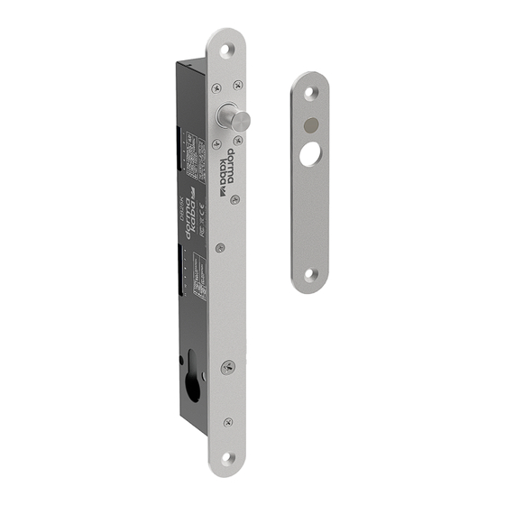
Operating Manual Product description 3 Product description 3.1 View Fig. 1: View Faceplate Housing Connection terminals Space for profile cylinder Latch Strike plate Mounting screws, self-tapping, 10G × 1" csk Screws M5 × 10 Screws M5 × 30 csk 3.2 Accessories (to be ordered separately) •... -
Page 6: Variants
Operating Manual 3.3 Variants Fail-safe (currentless opening) • DB25K Fail safe 2400001203 In the event of a power failure, the lock opens. This prevents people who are inside the secured area from becoming trapped in the event of an emergency. -
Page 7: Dimensions
Operating Manual Product description 3.5 Dimensions Fig. 2: Lock - dimensions Dimensions lock Dimensions latch housing (accessories) Dimensions short striking plate Dimensions of striker housing (accessories) Dimensions long striking plate Dimensions cover plate (accessories) (accessories) WN 60425 45532/16458 - 08/2022 Solenoid Drop Bolt with manual Key Override... -
Page 8: Operating Modes And Functions
High mechanical strength Profile cylinder The DB25K allows the inclusion of a profile cylinder. The profile cylinder allows the lock to be closed manually with the use of a key. The electronic access control is thus bypassed. Depending on the variant (fail-safe or fail-secure) and the connection type, the deadbolt is moved electrically or mechanically during manual closing. - Page 9 When the door is closed, the relocking time is started. • After the door is closed and the relocking time has elapsed, the lock latches the bolt. Functional overview of lock and connection variants DB25K Connection Multiple relocking Automatic. Re- Time for relocking...
-
Page 10: Mounting
Mounting Operating Manual 5 Mounting 5.1 Requirements for mounting Before mounting, the following aspects must be clarified: • Product variant • Type of installation • Installation position • Cable routing and wire cross-section Which product variant? The product variant must match the intended use: •... - Page 11 Operating Manual Mounting When installed in the floor, penetrating moisture or similar can contaminate the mechanics of the lock and render the lock unusable in the long term. Cable routing and conductor cross-section The routing and thus the length of the connecting cable must be determined. Three connecting wires are required for a fully functional lock.
-
Page 12: Example 1: Installing Lock And Strike Plate In Mortise Openings
Mounting Operating Manual 5.2 Example 1: Installing lock and strike plate in mortise openings The installation example describes the installation • of the lock into an insertion opening in the frame, • of the strike plate into an insertion opening in the door. Cut an insertion opening for the lock in the door frame. -
Page 13: Example 2: Install Lock On Frame And Strike Plate On Glass Door
Operating Manual Mounting 5.3 Example 2: Install lock on frame and strike plate on glass door. The installation example describes the installation • of the lock on a wooden frame, • the strike plate on a glass door. Two housings, a cover plate and a long strike plate are required for mounting (accessories). -
Page 14: Electrical Connection
Electrical connection Operating Manual 6 Electrical connection 6.1 Select power supply The lock is designed for low power consumption. Only when the deadbolt is moved does a larger current flow. Select the power supply according to the maximum current consumption. Note: If several locks are connected to one power supply at the same time, the maximum current consumptions of the individual locks are added together. -
Page 15: Three-Wire Connection (Recommended)
Operating Manual Electrical connection 6.3 Three-wire connection (recommended) In three-wire mode, the power supply is constantly connected to terminals + and - (terminals 1 and 3). To unlock the lock, control input CL (terminal 2) is supplied with voltage. Three-wire connection at fail-safe lock Connect terminals 1 and 9 with a wire jumper. -
Page 16: Connect Signaling Contacts For Door Position And Bolt Position
Electrical connection Operating Manual 6.5 Connect signaling contacts for door position and bolt position. The signaling contacts are used to monitor the door position, the bolt position and the profile cylinder, e.g. by an access control or alarm system. The door position is a simple normally open contact. -
Page 17: Maintenance And Cleaning
Operating Manual Maintenance and Cleaning At DB25K the switch M is factory set for Fail Safe or Fail Secure configuration and should not be changed. Connection M position Lock variant fail-safe (currentless opening) Three-wire connection Off (default) Two-wire connection - Not applicable -... -
Page 18: Disposal Of The Device
• Germany dormakaba Deutschland GmbH will properly dispose of goods delivered at the end of their useful life, in accordance with the legal regulations (ElektroG or the Electrical and Electronic Equipment Act in Germany). Any transport costs incurred are to be borne by the owner of the electronic device. - Page 19 Operating Manual Notes WN 60425 45532/16458 - 08/2022 Solenoid Drop Bolt with manual Key Override...
- Page 20 Deutschland GmbH DORMA Platz 1 58256 Ennepetal Germany Headquarters: +49 2333 793-0 Service DE: 0800 524 0246 www.dormakaba.com www.dormakaba.com...
Need help?
Do you have a question about the DB25K and is the answer not in the manual?
Questions and answers