Advertisement
Quick Links
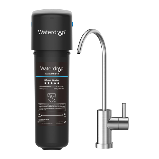
Quick Connect Undersink Water Filtration System
WD-UB system | Installation Instructions
System certi ed by WQA against NSF/ANSI Standards 42 for the reduction of the claims
speci ed on the Performance Data Sheet, and to NSF/ANSI 372 (≤0.25% lead).
Filter head
Stainless faucet
Cartridge
Quick-connect fitting
Specifications
Operating temperature
2-38℃/35-100℉
Working pressure
10-100psi (0.7-6.8bar)
Flow rate
0.75gpm (2.83lpm)
WD-RF10/WD-RF10-UF/MZ/AK: up to 11,000 gallons
Filter capacity
WD-RF15/WD-RF15-UF/MZ/AK: up to 19,000 gallons
WD-RF17/WD-RF17-UF/MZ/AK: up to 24,000 gallons
Feed water requirement
Municipal tap water
Note:
1. If using well water as the source, please make sure the feed water has been through a pre- ltration system, otherwise,
large particles in well water will clog the lter easily and shorten lter life.
2. The above form lists model numbers of only black lters. Please note that the white lter is di erent from the black
lter only in color. They have the same lter material and ltration capacity.
3. Actual lter life varies according to local water quality.
Precautions
• Do not use it with water that's microbiologically unsafe or of unknown quality without adequate disinfection.
• For use only with cold water.
• Do not freeze the lter, as this can cause cracking and water leakage.
• Do not allow children under 3 years old to have access to small parts during installation of this product.
• This installation must comply with all applicable state and local regulations.
• Turn o the water supply while replacing the lter.
Installation of the filter system
Step 1: Fix the filter head and the filter
1. Paste the assistant label to nish drilling. (Note: Mount the
water lter at least 2 inches higher than the ground for easier lter
change.)
2. Install the screw and reserve enough space to hang the lter.
3. Hang the lter system on the screw.
Step 2: Connect the water supply (cold water only)
1. There is an existing mark at the end of the tubing for you to
con rm if the tubing is fully inserted into the tting.
1/4" tubing
2. Connect one end of the 1/4" PE tubing to the inlet of the lter
head. Until you reach the mark on the tubing.
3. Shut o the water supply and remove the faucet hose.
3/8"-1/2" converter
4. Connect the feed water adapter and ensure that the rubber O-ring is loaded.
Feed water adapter
3/8"-1/2" converter
• If the angle valve outlet is 3/8", connect it to the water supply and faucet hose directly. (Figure 1)
• If the angle valve outlet is 1/2", you need to remove the above two ttings before connection. (Figure 2)
Teflon tape
Figure 1
Step 3: Install the faucet
Note: If there is no hole in your kitchen sink or countertop, you have to drill one (1")or use the hole for
the soap dispenser.
1. Insert the faucet spout into the faucet body.
2. Insert the faucet stem into the hole on the countertop.
Under the sink, slip on other parts in the order shown in
the picture.
3. Firmly insert the quick-connect tting onto the faucet stem.
4. Connect one end of the tubing to the quick-connect
tting of the faucet, then lock the clip. If you want to pull
out the tubing, remove the clip rst.
5. Connect the other end to the outlet of the lter head.
6. Push the tubing into the tting until you reach the
mark on the tubing.
Mark for
full insert
Figure 2
3/8" Cold water valve
1/2" Cold water valve
Faucet spout
Faucet body
Countertop
Faucet stem
Mounting washer
Nut
Clip
Quick-connect
fitting
Clip
Step 4: Check the leaks and flush the filter
1. In the event of water leakage, turn o the water
supply. If the water leakage is occurring at position
1, wrap Te on tape on the external thread. If the
water leakage is occurring at position 2, 3 or 4,
check whether the tubing is fully inserted into the
ttings. If not, insert it again until you reach the
mark on the tubing.
2. Flush the lter for 5 minutes before use.
To disconnect
Use your thumb and index nger to press down on the lock sleeve. Use your other hand to pull out the
hose from the tting.
Note: Please do not pull out the tubing directly, or else it will damage the tting and cause leakage.
Press
Press
Filter replacement
1. It's recommended to turn o the water supply and turn
on the faucet to release the water pressure.
2. Rotate 1/4 turn to the left to remove the lter.
3. Take out the new lter and remove the protective cap.
4. Rotate 1/4 turn to the right to install the lter. Ensure
that the lter's triangle mark is aligned with the
connection mark.
5. Turn on the cold water valve and ush for 5 minutes.
Remove the filter
Frequently asked questions
Q: What should I do if water leaks after installation?
A: In the event of water leakage, turn o the water supply. If the water leakage is occurring at the
thread, wrap Te on tape on the external thread. If the water leakage is occurring at the quick
connection position, insert the quick-connect tting to the end and make sure the hoses hit the
bottom of the tting. Contact us for solutions if the water leakage persists.
2
Outlet
Inlet
1
3
4
Hot
Cold
Filter system
Pull
Install the filter
Advertisement

Related Manuals for Waterdrop WD-UB


Summary of Contents for Waterdrop WD-UB
- Page 1 1, wrap Te on tape on the external thread. If the water lter at least 2 inches higher than the ground for easier lter WD-UB system | Installation Instructions water leakage is occurring at position 2, 3 or 4, change.)
- Page 2 Q: Why doesn’t the TDS value lower after filtration? Performance data sheet A: The main purpose of this waterdrop lter is not to remove TDS. TDS stands for total dissolved solids, System Model No.: and it is basically composed of inorganic salts and a small amount of organic matter. The lter can WD-10UB-MZ/WD-10UB-AK/WD-10UB/WD-10UBW/WD-10UBW-UF/WD-10UBW-AK/WD-10UBW-MZ/ remove harmful substances while keeping bene cial trace elements.
Need help?
Do you have a question about the WD-UB and is the answer not in the manual?
Questions and answers