
Related Manuals for Western Digital WD Series


Summary of Contents for Western Digital WD Series
- Page 1 Western Digital SCSI Hard Drives WD Enterprise • WDE2170 • WDE4360 Installation Guide Released 10/18/96...
- Page 2 Western Digital Corporation reserves the right to change specifications at any time without notice. Western Digital is a registered trademark. WD Enterprise is a trademark of Western Digital Corporation. Other marks may be mentioned herein that belong to other companies.
- Page 3 507-286-7926 (fax) If you need additional information or help during installation or during normal use of this product, contact Western Digital Technical Support. Our customer support staff will attempt to answer your installation questions by phone or issue a service authorization number for repair or replacement of your product.
-
Page 4: Table Of Contents
TABLE OF CONTENTS INTRODUCTION..............1 Product Description ............1 Product Features ............2 GENERAL INFORMATION ..........4 Handling Precautions ............ 4 ESD Protection ................5 Before Installing the Drive..........6 PREPARING FOR INSTALLATION.........7 Overview ..............7 Mounting Restrictions........... 8 Ventilation..................8 Orientation..................8 Mounting ..................9 Setting the Drive Jumpers ........... - Page 5 Multiple Drive Installations ......... 25 INSTALLING THE DRIVE ..........26 Opening the Computer System............27 Preparing the Drive for Installation..........27 If Your Drive has a 50-pin or 68-pin Connector ......28 If Your Drive has an 80-pin Connector ........35 Closing the Computer System .............37 USING THE DRIVE ............
- Page 6 LIST OF FIGURES Figure 1. WD Enterprise Drive (Top and Front View) ....2 Figure 2. Mounting Hole Locations..........9 Figure 3. Option Block..............10 Figure 4. Disable Auto Start Jumper ..........13 Figure 5. Auto Start Delay Jumper..........14 Figure 6. SCAM Jumper ...............15 Figure 7.
-
Page 7: Introduction
Mbits/s. There are currently two models available in the WD Enterprise series: the WDE4360 and WDE2170. The “WDE” prefix represents the Western Digital Enterprise group of products and the four numeric digits denote the drive’s capacity in megabytes. The model number listed on the product label may include additional customer-specific information. -
Page 8: Product Features
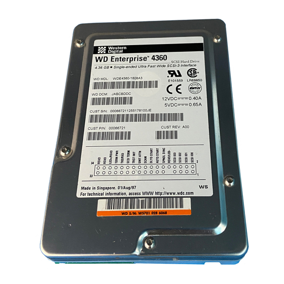
Figure 1. WD Enterprise Drive (Top and Front View) PRODUCT FEATURES The WD Enterprise drive offers the following features: • Advanced Caching — Including Read and Write Caching, Pre-fetch, and Adaptive Caching • Command Queuing — Supports both tagged and untagged queuing;... - Page 9 • Error Correction Code (ECC) — ECC on-the-fly is a feature that allows some ECC errors to be corrected in hardware with no delays to data transfer. • 512 KB Data Buffer — The entire data buffer is user accessible. A 1 MB option is also available. For more technical information and specifications on the WD Enterprise drives, see the Reference section of this manual.
-
Page 10: General Information
• Do not attempt to remove the drive cover. Servicing components in the sealed compartment requires special cleanroom facilities. Failure to observe this restriction will void the warranty. • For additional handling information, refer to the Western Digital 3.5-inch Drive Handling Guide (document number SO999). " Released 10/18/96... -
Page 11: Esd Protection
ESD Protection To prevent drive damage it is essential to keep the drive in an ESD safe environment. Several precautions can be taken to avoid permanent damage to the drive. • Keep the drive in the shielded anti-static bag prior to testing or installation. -
Page 12: Before Installing The Drive
• Jumper shunts, if you change the drive configuration. Jumper shunts are available from your local computer dealer or from Western Digital technical support. • Interface cable (for 50-pin or 68-pin models) • A drive tray or mounting rails, depending upon system requirements •... -
Page 13: Preparing For Installation
PREPARING FOR INSTALLATION OVERVIEW This section provides the steps necessary to prepare the WD Enterprise hard drive for installation in your system. Because the WD Enterprise WDE2170 and WDE4360 drives are compatible with a wide range of computer systems, this manual does not include system-specific information. -
Page 14: Mounting Restrictions
Since improper mounting may distort the drive frame and impair its proper function, mounting the drive securely will ensure maximum performance. Western Digital provides technical support to those customers requiring assistance with mounting design. Some customers may wish to review their system... -
Page 15: Mounting
Mounting Four 6-32 UNC screws are used to mount the drive. To avoid stripping the mounting-hole threads, the maximum torque applied to the screws should not exceed 6.0 in-lb. (0.675 N-m). Be aware of the following: • The drive features four mounting holes on either side of the drive and four mounting holes on the bottom. -
Page 16: Setting The Drive Jumpers
SETTING THE DRIVE JUMPERS NOTE: Before installing your WD Enterprise drive, you should review the SCSI concepts presented in this section. The information will help you configure each WD Enterprise drive to operate properly in your system. The drive is designed for use in a variety of systems. Therefore, several configuration options can be set using the option block on the front of the drive (end opposite the SCSI connector). -
Page 17: Scsi Id Numbers
SCSI ID Numbers Each device on the SCSI bus requires a unique SCSI ID number (0 to 7 for 8-bit devices, 0 to 15 for 16-bit devices). Option block pins 1 through 8 are used to set the SCSI IDs. Refer to Table 1 for a complete matrix of jumper settings. - Page 18 NOTE: The WD Enterprise drive supports the SCSI Configured Automatically (SCAM) option, which automatically assigns SCSI ID numbers and resolves ID conflicts upon bootup. If your SCSI controller and other SCSI devices support SCAM, you do not need to manually assign a SCSI ID to the hard drive.
-
Page 19: Disable Auto Start
Disable Auto Start The WD Enterprise drive can be configured to Auto Start, or automatically spin up when power is applied to the drive. If the drive is configured to disable Auto Start, it powers up, but will not spin up until a start unit command is issued by an operator. -
Page 20: Auto Start Delay
Auto Start Delay This feature delays the start-up process to avoid an initial power surge when several drives are powered up at once. The delay time (default) is 4 seconds between drives, or the SCSI ID multiplied by 4 seconds. Let’s say you have three hard drives in your system, and they are set to SCSI IDs 0, 1, and 2. -
Page 21: Scam
SCAM The WD Enterprise drive supports the SCSI Configured Automatically (SCAM) option, which allows it to function as a SCAM level 2 device. NOTE: In order to use this feature, the host bus adapter must support SCAM. Option block pins 17 and 18 are dedicated to the SCAM feature. -
Page 22: Disable Unit Attention
Disable Unit Attention Whenever a target (WD Enterprise drive) has been reset by a power-on or reset sequence, it communicates a unit attention message to the initiator (host bus adapter). Option block pins 19 and 20 are dedicated to the Disable Unit Attention option. -
Page 23: Disable Target Initiated Synchronous/Wide Negotiation
Disable Target Initiated Synchronous/Wide Negotiation During the power up sequence, the initiator (host bus adapter) and the target (WD Enterprise drive) negotiate and agree upon three items: bus width, bus speed, and synchronous/asynchronous data transfer. Either the initiator or the target can start the negotiation process, and once this process is completed successfully, all “data in”... -
Page 24: Scsi Termination
SCSI Termination To ensure reliable communication, the SCSI bus must be properly terminated. Devices located at the physical ends of the SCSI bus should have their terminators enabled. All other devices must have their terminators disabled. Option block pins 23 and 24 are dedicated to the SCSI Termination option. -
Page 25: Termination Power (Termpwr)
Termination Power (TERMPWR) WD Enterprise drives have the ability to supply +5V to the SCSI bus for termination. Option block pins 27 and 28 are dedicated to TERMPWR. If you want the drive to supply TERMPWR to the SCSI bus, install a jumper as shown in Figure 10. -
Page 26: Spindle Synchronization
For more details regarding the sync offset, refer to the Western Digital SCSI Implementation Guide (document number 4096-0011116) and the WD Enterprise Technical Reference Manual (document number 4079-001045). -
Page 27: Led Support
LED Support If your system configuration allows the use of an activity LED external to the WD Enterprise drive, you can power the LED from the drive. Pins 10 and 29 are dedicated to LED support, as shown in Figure 12. To install an external activity LED, connect the positive lead (anode) of the LED to pin 29 and the negative lead (cathode) to pin 10. -
Page 28: Reserved Pins
Read/Write Error Recovery Page, Format Device Page, and Caching Page. The Mode Select command allows drive characteristics to be customized to meet your system requirements. Refer to the Western Digital SCSI Implementation Guide (document number 4096-001116) for more information. Remote Option Block... -
Page 29: Scsi Cable Length Restrictions
SCSI CABLE LENGTH RESTRICTIONS Single-ended SCSI drives allow cable lengths of up to 6 meters (19.68 feet). Users who plan to use “Fast” and “Ultra Fast” data transfers with single-ended models should follow all the ANSI SCSI guidelines for these operations. Differential SCSI drives allow cable lengths of up to 25 meters (82.02 feet). -
Page 30: Connector Types
CONNECTOR TYPES 50-pin SCSI Connector 50-pin models use a high density connector which is compatible with ANSI SCSI “A” style connector specifications. It can transfer data in 8-bit (narrow) mode only. 68-pin SCSI Connector 68-pin models use a high density connector which is compatible with ANSI SCSI “P”... -
Page 31: Multiple Drive Installations
MULTIPLE DRIVE INSTALLATIONS If your system requires multiple devices, you may install up to eight SCSI devices (including the host bus adapter) on an 8-bit SCSI bus; up to sixteen SCSI devices (including the host bus adapter) on a 16-bit SCSI bus, or up to 32 devices (including the host bus adapter) on a 16- bit SCSI bus with a dual processor host bus adapter. -
Page 32: Installing The Drive
INSTALLING THE DRIVE Because the Enterprise WDE2170 and WDE4360 drives are compatible with a wide range of computer systems and host bus adapters, this manual does not include system- specific information. If the information contained in the following sections does not adhere to your setup, refer to your computer system documentation for further details. -
Page 33: Opening The Computer System
Opening the Computer System 1) Turn OFF the power to the computer system and all attached peripheral devices. 2) Unplug the AC power cable from the wall outlet. 3) Remove all cables from the back of the computer system. 4) Remove the screws attaching the computer system’s cover using a non-magnetic screwdriver. -
Page 34: If Your Drive Has A 50-Pin Or 68-Pin Connector
If Your Drive has a 50-pin or 68-pin Connector 1) Using a non-magnetic screwdriver and four mounting screws, mount the 50-pin or 68-pin drive in the computer system’s mounting frame as shown in Figure 14. Use four 6-32 mounting screws. Do not install the screws past .150-inch. -
Page 35: Figure 14. Installation Of 50- Or 68-Pin Drive
Figure 14. Installation of 50- or 68-pin Drive 2) Obtain the appropriate type of SCSI ribbon cable, 50- pin or 68-pin. 3) Identify pin 1 on the ribbon cable. The colored stripe indicates pin 1. 4) Connect the ribbon cable connector to the hard drive by matching pin 1 on the ribbon cable with pin 1 on the hard drive connector. -
Page 36: Figure 15. Attaching The 50-Pin Scsi Cable
Figure 15. Attaching the 50-pin SCSI Cable Figure 16. Attaching the 68-pin SCSI Cable Released 10/18/96... - Page 37 NOTE: If multiple devices are attached to the SCSI bus, they must be daisy-chained using a ribbon cable with multiple connectors. The ends of the cable must be connected to terminated devices. If the cable contains more connectors than needed for the devices on the bus, mid-cable connectors may remain unused.
-
Page 38: Figure 17. Attaching A 50- Or 68-Pin Scsi Cable To A Scsi Controller Card
Figure 17. Attaching a 50- or 68-pin SCSI Cable to a SCSI Controller Card Released 10/18/96... -
Page 39: Figure 18. Attaching A 50- Or 68-Pin Scsi Cable To The
Figure 18. Attaching a 50- or 68-pin SCSI Cable to the Motherboard Released 10/18/96... -
Page 40: Figure 19. Attaching The Power Supply Cable
NOTE: Before completing steps 6 and 7, ensure that power to the computer system is turned off. Hot-plugging power to the drive is not recommended. 6) Locate an available 4-pin power supply connector cable inside the computer system. 7) Connect the 4-pin power cable to the power connector on the drive. -
Page 41: If Your Drive Has An 80-Pin Connector
If Your Drive has an 80-pin Connector NOTE: The SCSI connection and power connection is handled by a single SCA-2 connector. 1) Mount the 80-pin drive in a drive tray using four mounting screws. 2) Slide the drive/tray assembly into the designated drive slot, making sure that the end with the SCSI connector is inserted first. -
Page 42: Figure 21. Connecting An 80-Pin Drive To A Backplane
3) Ensure that the drive is properly seated on the backplane connector. Refer to Figure 21. NOTE: This connection must be secure. Figure 21. Connecting an 80-pin Drive to a Backplane Released 10/18/96... -
Page 43: Closing The Computer System
Closing the Computer System 1) Verify all cable connections. 2) To prevent damage to the SCSI ribbon cables and power cables, make sure all cables are neatly placed inside the computer system’s chassis. 3) Replace the cover and install screws using a non- magnetic screwdriver. -
Page 44: Using The Drive
USING THE DRIVE To prepare your drive for use, you must install your operating system, application software, and if necessary, host bus adapter software. Consult your system and software documentation for additional information. It is extremely important to regularly back up the data on your hard drive. -
Page 45: Reference
• (80-pin SCA-2) Rotational Speed: 7200 RPM 7200 RPM Bytes per Sector: Western Digital defines a megabyte (MB) as 1,000,000 bytes and a gigabyte (GB) as 1,000,000,000 bytes. Differential option available on 68-pin and 80-pin models. RELIABILITY SPECIFICATIONS MTBF: 1,000,000 hours... -
Page 46: Physical Dimensions
PHYSICAL DIMENSIONS WDE2170 WDE4360 Form Factor: 3.5 inches 3.5 inches Height: 1.00 ± 0.02 inches 1.00 ± .02 inches 25.4 ± 0.50 mm 25.4 ± 0.50 mm Length: 5.75 ± 0.02 inches 5.75 ± 0.02 inches 146.05 ± 0.50 mm 146.05 ±... -
Page 47: Environmental Specifications
ENVIRONMENTAL SPECIFICATIONS Shock Operating: 10G (3 ms) Non-operating: 70G (3 ms) Non-operating Rotational Shock: 10,000 rad/s (3 ms) Vibration Operating: Sine Sweep 5-20 Hz, 0.037 inch (double amplitude displacement) 20-400 Hz, 0.75G (zero-to-peak) Non-operating: Sine Sweep 5-20 Hz, 0.098 inch (double amplitude displacement) 20-400 Hz, 2.0G (zero-to-peak) Sweep Rate: One octave/minute minimum... -
Page 48: Troubleshooting
TROUBLESHOOTING If you encounter a problem during installation of your WD Enterprise drive, first review your computer system documentation to ensure that you followed the setup procedures correctly, then use this checklist: • Is the system plugged in and are all power connections secure? •... - Page 49 If a problem persists, contact the manufacturer of the host bus adapter to verify the hardware and software setup is correct. If you have additional questions, contact your local dealer, the Western Digital web site (at www.wdc.com), or Western Digital Technical Support at 1-888-WDC-SCSI for assistance. "!
-
Page 50: Regulatory Agency Information
REGULATORY AGENCY INFORMATION The drive has met the following regulatory agency standards: • Underwriters Laboratories: UL-Standard 1950, Standard for Safety of Information Technology Equipment including Electrical Business Equipment File Number E101559 • Federal Communication Commission: Verified to comply with FCC Rules for Radiated and Conducted Emission, Part 15, Subpart B, for Class B Equipment •... -
Page 51: Radio Frequency Interference Statement
RADIO FREQUENCY INTERFERENCE STATEMENT FCC Notice This Western Digital Enterprise product has been verified to comply with the limits for a Class B computing device pursuant to subpart B Part 15 of FCC rules. This does not guarantee that interference will not occur in individual installations. -
Page 52: Warranty Information
WARRANTY INFORMATION WD ENTERPRISE HARD DRIVES OBTAINING SERVICE Western Digital Corporation (“WDC”) values your business and always attempts to provide you the very best of service. If this Product ever requires maintenance, either contact the dealer from whom you originally purchased the Product or telephone WDC’s Technical Support... -
Page 53: Limited Warranty
LIMITED WARRANTY WDC warrants that the Product, in the course of its normal use, will be free from defects in material and workmanship for a period of five (5) years and will conform to WDC’s specification therefor. This limited warranty shall commence on the purchase date appearing on your purchase receipt. - Page 54 MERCHANTABILITY OR FITNESS FOR A PARTICULAR PURPOSE, AND b) ANY AND ALL OBLIGATIONS AND LIABILITIES OF WDC FOR DAMAGES INCLUDING, BUT NOT LIMITED TO ACCIDENTAL, CONSEQUENTIAL, OR SPECIAL DAMAGES, OR ANY FINANCIAL LOSS, LOST PROFITS OR EXPENSES, OR LOST DATA ARISING OUT OF OR IN CONNECTION WITH THE PURCHASE, USE OR PERFORMANCE OF THE PRODUCT, EVEN IF WDC HAS BEEN ADVISED...
- Page 55 HO290...
Need help?
Do you have a question about the WD Series and is the answer not in the manual?
Questions and answers