Table of Contents
Advertisement
Quick Links
OWNER'S MANUAL
Instructions for the installation, operation
and maintenance of all Centerline™ by Traulsen Compacts:
Undercounter Refrigerators & Freezers*
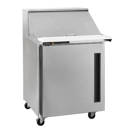
Prep Tables and Mega Tops*
*Please Note: This manual is intended for use with the above referenced equipment manufactured after June 01, 2022.
4401 Blue Mound Road Fort Worth, Texas 76106 (USA)
Phone: 800.825.8220 | Service Fax: 817.740.6757 | E-mail: service@traulsen.com | Website: centerlinefoodequipment.com
Hours of Operation: Monday - Friday 7:30 a.m. - 4:30 p.m. (CST)
Advertisement
Table of Contents

Related Manuals for Traulsen centerline CLUC-60R-SD-WTRR


Summary of Contents for Traulsen centerline CLUC-60R-SD-WTRR
- Page 1 *Please Note: This manual is intended for use with the above referenced equipment manufactured after June 01, 2022. 4401 Blue Mound Road Fort Worth, Texas 76106 (USA) Phone: 800.825.8220 | Service Fax: 817.740.6757 | E-mail: service@traulsen.com | Website: centerlinefoodequipment.com Hours of Operation: Monday - Friday 7:30 a.m. - 4:30 p.m. (CST)
-
Page 2: Table Of Contents
SYS2 (REFA): • Model = The model # of your Traulsen unit Hi Press. (PRESH): • (S/N) Serial Number = The permanent ID# of your Traulsen unit Lo Press. (PRESL): Input Power (ELIN) - FOR INDOOR USE ONLY • Refrigerant SYS1 = System 1 Refrigerant type used and... -
Page 3: Receipt Inspection
Under no condition may a damaged unit be returned side in this manner. The caster bolts are tightened using a to Traulsen without first obtaining written permission (return 1/2” socket wrench. Casters with locks should be installed authorization). You may contact Traulsen customer care at in the front for easy access to locking mechanism. -
Page 4: D) Installing Drain Pan
III. INSTALLATION (continued) III. d - INSTALLING DRAIN PAN III. e - SHELF CLIPS FOR DOOR MODELS (cont’d) Centerline compact models are shipped with the condensate pan (half-size sheet pan) wrapped up and stored inside the unit. Remove the condensate pan and slide it on the rails underneath the cabinet. -
Page 5: I) Cutting Board Assembly
III. INSTALLATION (continued) III. i - CUTTING BOARD ASSEMBLY III. j - INSTALLING BACKSPLASH All 27”, 36”, 48”, 60”, & 72” wide compact undercounter On prep tables and mega top tables, the cutting board may models can be supplied with an optional backsplash that require assembly at the site. -
Page 6: Operation
IV. OPERATION V. CARE AND MAINTENANCE IV. c - FREEZERS (cont’d) Both refrigerators and freezers do not require manual defrosting. However, manual defrost option is available on The electric heaters (attached to the evaporator coil and the control, if required. drip pan) are energized. -
Page 7: F) Divider Bars
V. CARE AND MAINTENANCE (continued) IV. f - DIVIDER BARS V. b - CLEANING THE INTERIOR (cont’d) Top Rail: Centerline compacts are provided with standard width pan divider bars. Pans are not provided with the unit. To remove the drawers, the lock tab must be unlocked by sliding the lock tab forward and then up, to loosen the slides (see figure 8). -
Page 8: D) Condensate Removal System Care
V. CARE AND MAINTENANCE (continued) V. e - DOOR RE-HINGING (cont’d) V. d - CONDENSATE REMOVAL SYSTEM CARE Carefully lay the door down on a padded flat surface. The Condensate removal is provided by evaporation at the pan door must be rotated 180° to mount on the other side of at the bottom of the equipment cabinet and does not need a cabinet. -
Page 9: G) Replacing The Gaskets
V. CARE AND MAINTENANCE (continued) VI. CONTROL BASICS V. g - REPLACING THE GASKETS Your new Centerline Refrigerator or Freezer is equipped with a digital control, which precisely regulates operation. It is To replace the gasket, grasp it firmly by one corner and pull supplied from the factory completely ready for use. -
Page 10: C) Initiating A Defrost
VI. CONTROL BASICS (continued) VI. c - INITIATING A DEFROST VI. c - INITIATING A DEFROST (cont’d) Automatic defrost: Resuming thermostatic cycle: Defrost starts automatically as soon as the time set with When defrost is over, if DRN is greater than 0, all outputs parameter DFT has elapsed. -
Page 11: E) Technical Data
VI. CONTROL BASICS (continued) VI. e - TECHNICAL DATA Power supply TRL-002..W 100-240Vac ±10%, 50/60Hz, 3W Relay output max loads (240Vac) TRL-002..S/T..-. TRL-002..Q/R..-. Compressor 16A resistive 12A resistive 12 FLA 48 RLA 12 FLA 48 RLA Evap. Fan 16A resistive 8A resistive 4 FLA 12 RLA 4 FLA 12 RLA... - Page 12 VI. CONTROL BASICS (continued) RANGE DESCRIPTION -58..SPH Minimum limit for SP setting. SPL...180° Maximum limit for SP setting. SPL... SPH Setpoint (value to be maintained in the room). REF; HEA Refrigerating (REF) or Heating (HEA) control mode. 1...10° Thermostat OFF -> ON differential. 0...10°...
- Page 13 VI. CONTROL BASICS (continued) RANGE DESCRIPTION Defrost display mode. During defrost the display will show: RT: the real temperature; LT : the last temperature before defrost; SP : the current setpoint value; DEF : “dEF”. 0...60min Display delay. The display shows the information selected with parameter DDM during defrost and for DDY minutes after defrost termination.
- Page 14 VI. CONTROL BASICS (continued) RANGE DESCRIPTION IIH1 0... 10° Thermostat ON->OFF differential in mode 2. IIDF 0...250 Time interval among defrosts in mode 2 in x10 minutes. IIFC NON; Fan control in mode 2. See FCM. TMP; 1...5 Controller sensitivity for the automatic switchover from Group I to Group II (1=minimum, 5=maximum). 1…5 Controller sensitivity for the automatic switchover.
- Page 15 VI. CONTROL BASICS (continued) RANGE DESCRIPTION NON; AUX 1 output operation LGT; NON : output disabled (always off). 0-1; LGT : output enabled for light control. 2CU; 0-1 : the relay contacts follow the on/standby state of controller. 2EU; 2CU : output programmed for the control of an auxiliary compressor. ALO;...
-
Page 16: F) Components And Wiring Diagram
VI. CONTROL BASICS (continued) VI. f - COMPONENTS AND WIRING DIAGRAM Control Wiring Diagram: Indications: Thermostat output Fan output Defrost output Activation of 2 patameter set Alarm Manual activation / Increase button Exit / Stand-by button -15-... -
Page 17: Troubleshooting Guide
VII. TROUBLESHOOTING GUIDE VII. a -TROUBLESHOOTING GUIDE FIND YOUR PROBLEM HERE REMEDY a.Check if cord & plug has been disconnected. 1. Condensing unit fails to start. b.Check control temperature setting. a.Are doors closing properly? 2. Condensing unit operates for prolonged periods or b.Dirty condenser or filter. -
Page 18: Service/Warranty Information
Centerline by Traulsen reserves the right to change specifications or discontinue models without notice. VIII. b - SPARE PARTS INFORMATION To purchase replacement parts or to speak to service support for Centerline by Traulsen units please contact our Ft. Worth facility by phone at 800-825-8220 or fax to 817-740-6748 (parts) or 817-740-6757 (service). -
Page 19: D) Warranty Statement
Purchaser. In the case of a nonconforming part, Purchaser must return the part to Traulsen within 30 days from the date of repair. Failure to return a claimed defective part to Traulsen within the 30 days will waive the right to the warranty claim. - Page 20 4401 Blue Mound Road Fort Worth, Texas 76106 (USA) Phone: 800.825.8220 | Service Fax: 817.740.6757 | E-mail: service@traulsen.com | Website: centerlinefoodequipment.com Form Number: TR36231 | Part Number: 375-60363-00 (Rev. C) | Revision Date: 09-21-22 Traulsen © All Rights Reserved...
Need help?
Do you have a question about the centerline CLUC-60R-SD-WTRR and is the answer not in the manual?
Questions and answers