Table of Contents
Advertisement
Quick Links
OWNER'S MANUAL
Instructions for the installation, operation and
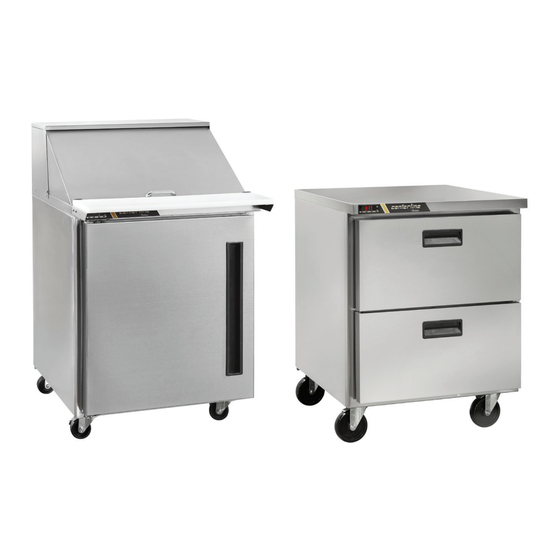
maintenance of all Centerline™ by Traulsen Compacts:
Undercounter Refrigerators & Freezers*
Prep Tables and Mega Tops*
*Please Note: This manual is intended for use with the above referenced equipment manufactured after June 01, 2022.
4401 Blue Mound Road Fort Worth, Texas 76106 (USA)
Phone: 800.825.8220 | Service Fax: 817.740.6757 | E-mail: service@traulsen.com | Website:
centerlinefoodequipment.com
Hours of Operation: Monday - Friday 7:30 a.m. - 4:30 p.m. (CST)
Advertisement
Table of Contents

Related Manuals for Traulsen centerlineCLUC-27R-SD-WTL


Summary of Contents for Traulsen centerlineCLUC-27R-SD-WTL
- Page 1 *Please Note: This manual is intended for use with the above referenced equipment manufactured after June 01, 2022. 4401 Blue Mound Road Fort Worth, Texas 76106 (USA) Phone: 800.825.8220 | Service Fax: 817.740.6757 | E-mail: service@traulsen.com | Website: centerlinefoodequipment.com Hours of Operation: Monday - Friday 7:30 a.m. - 4:30 p.m. (CST)
-
Page 2: Table Of Contents
Hi Press. (PRESH): • Model = The model # of your Traulsen unit Lo Press. (PRESL): Input Power (ELIN) - FOR INDOOR USE ONLY • (S/N) Serial Number = The permanent ID# of your Traulsen unit 115 V 60 Hz 3.3 A (3,30 A) •... -
Page 3: Receipt Inspection
THE CABINET MUST BE BLOCKED AND STABLE carrier and file a freight claim. Under no condition may BEFORE INSTALLING CASTERS. a damaged unit be returned to Traulsen without first To change the legs or casters, first raise and block the obtaining written permission (return authorization). You cabinet a minimum of 7”... -
Page 4: D) Installing Drain Pan
III. INSTALLATION (continued) III. d - INSTALLING DRAIN PAN III. e - SHELF CLIPS FOR DOOR MODELS (cont’d) Centerline compact models are shipped with the condensate pan (half-size sheet pan) wrapped up and stored inside the unit. Remove the condensate pan and slide it on the rails underneath the cabinet. -
Page 5: I) Cutting Board Assembly
III. INSTALLATION (continued) III. i - CUTTING BOARD ASSEMBLY III. j - INSTALLING BACKSPLASH (cont’d) On prep tables and mega top tables, the cutting board may require assembly at the site. Install cutting board brackets on each side with two screws. With brackets installed, slide the cutting board in at an angle under the lip in the back and then let it rest down with the pins running through the holes on the board... -
Page 6: B) Refrigerators
IV. OPERATION (continued) IV. b - REFRIGERATORS IV. c - FREEZERS (cont’d) During normal operation, a refrigerator continuously The microprocessor control is set from the factory to circulates above-freezing cabinet air through the evaporator terminate defrost at 25 minutes for freezers in the event coil. -
Page 7: Care And Maintenance
V. CARE AND MAINTENANCE V. c - CLEANING THE CONDENSER COIL DISCONNECT ELECTRICAL POWER SUPPLY BEFORE CLEANING ANY PARTS OF THE UNIT. Check the condenser coil periodically. The operating V. a - CLEANING THE EXTERIOR environment will affect the required frequency of clean- ing. -
Page 8: E) Door Re-Hinging
V. CARE AND MAINTENANCE (continued) V. e - DOOR RE-HINGING V. e - DOOR RE-HINGING (cont’d) The door(s) on all compact models can be easily re-hinged NOTE: The lower hinge plate is under spring tension. Grasp in the field. Existing hinge cartridge and top hinge bracket the lower hinge plate while keeping a firm grip on the can be reused but an opposite side bottom hinge bracket plate, carefully slide it out the bottom of the door just far... -
Page 9: H) Preparing For Extended Shutdown
V. CARE AND MAINTENANCE (continued) VI. CONTROL BASICS (continued) V. h - PREPARING FOR EXTENDED SHUTDOWN • When button is released, the new value is stored. If the refrigerator is not to be used for an extended period VI. c - INITIATING A DEFROST of time, disconnect the electrical power supply and open Automatic defrost: the doors. -
Page 10: D) Configuration Parameters
VI. CONTROL BASICS (continued) VI. c - INITIATING A DEFROST (cont’d) Measurement Range <0.5 within the measurement range Resuming thermostatic cycle: Operating Conditions When defrost is over, if DRN is greater than 0, all outputs -10... +50°C; 15%...80% r.H. will remain off for DRN minutes, in order for the ice to melt CE (Approvals and Reference Norms) completely and the resulting water to drain. - Page 11 VI. CONTROL BASICS (continued) RANGE DESCRIPTION -58..SPH Minimum limit for SP setting. SPL...180° Maximum limit for SP setting. SPL... SPH Setpoint (value to be maintained in the room). REF; HEA Refrigerating (REF) or Heating (HEA) control mode. 1...10° Thermostat OFF -> ON differential. 0...10°...
- Page 12 VI. CONTROL BASICS (continued) RANGE DESCRIPTION Defrost display mode. During defrost the display will show: RT: the real temperature; LT : the last temperature before defrost; SP : the current setpoint value; DEF : “dEF”. 0...60min Display delay. The display shows the information selected with parameter DDM during defrost and for DDY minutes after defrost termination.
- Page 13 VI. CONTROL BASICS (continued) RANGE DESCRIPTION IISH IISL... 180° Maximum limit for IISP setting. IISP IISL... IISH Setpoint in mode 2. IIH0 1... 10° Thermostat OFF->ON differential in mode 2. IIH1 0... 10° Thermostat ON->OFF differential in mode 2. IIDF 0...250 Time interval among defrosts in mode 2 in x10 minutes.
- Page 14 VI. CONTROL BASICS (continued) RANGE DESCRIPTION 0…600 sec Activation time of OA1 0…600 sec Pause between OA1 activation NON; AUX 1 output operation NON : output disabled (always off). LGT; LGT : output enabled for light control. 0-1; 0-1 : the relay contacts follow the on/standby state of controller. 2CU;...
-
Page 15: F) Components And Wiring Diagram
VI. CONTROL BASICS (continued) VI. f - COMPONENTS AND WIRING DIAGRAM Indications: Thermostat output Fan output Defrost output Activation of 2 patameter set Alarm Manual activation / Increase button Exit / Stand-by button Control Wiring Diagram: -14-... -
Page 16: Troubleshooting Guide
VII. TROUBLESHOOTING GUIDE VII. a -TROUBLESHOOTING GUIDE FIND YOUR PROBLEM HERE REMEDY a.Check if cord & plug has been disconnected. 1. Condensing unit fails to start. b.Check control temperature setting. a.Are doors closing properly? 2. Condensing unit operates for prolonged periods or b.Dirty condenser or filter. -
Page 17: Service/Warranty Information
Centerline by Traulsen reserves the right to change specifications or discontinue models without notice. VIII. b - SPARE PARTS INFORMATION To purchase replacement parts or to speak to service support for Centerline by Traulsen units please contact our Ft. Worth facility by phone at 800-825-8220 or fax to 817-740-6748 (parts) or 817-740-6757 (service). -
Page 18: Notes
IX. NOTES -17-... - Page 19 IX. NOTES -18-...
- Page 20 4401 Blue Mound Road Fort Worth, Texas 76106 (USA) Phone: 800.825.8220 | Service Fax: 817.740.6757 | E-mail: service@traulsen.com | Website: centerlinefoodequipment.com Form Number: TR36231 | Part Number: 375-60363-00 (Rev. E) | Revision Date: 03-2024 Traulsen © All Rights Reserved...
Need help?
Do you have a question about the centerlineCLUC-27R-SD-WTL and is the answer not in the manual?
Questions and answers