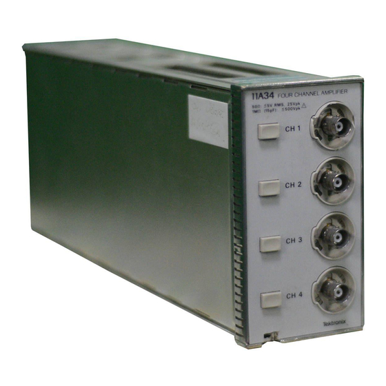
Tektronix 11A34 Service Reference Manual
Four-channel amplifier
Hide thumbs
Also See for 11A34:
- User reference supplement (45 pages) ,
- User reference supplement (54 pages)
Advertisement
Quick Links
WARNING
The following servicing instructions are for use by qualified
personnel only. To avoid personal injury. do not perform any
servicing unless you are qualified to do So. Refer to the Safety
Summary prior to perfarming any service.
Please check for CHANGE INFORMATION at the rear of this manual.
Advertisement

Related Manuals for Tektronix 11A34


Summary of Contents for Tektronix 11A34
- Page 1 WARNING The following servicing instructions are for use by qualified personnel only. To avoid personal injury. do not perform any servicing unless you are qualified to do So. Refer to the Safety Summary prior to perfarming any service. Please check for CHANGE INFORMATION at the rear of this manual.
- Page 3 Instrument Serial Numbers Each instrument manufactured by Tektronix has a serial number on a panel insert or tag, stamped on the chassis. The first letter in the serial number designates the country of manufacture. The last five digits of the serial numbsr are assigned sequentially end are unique to each Instrumsnt.
- Page 4 This seotton contains proceduresto specifications, and to manually set all internal adjustments. This procedure provides a logical sequence of check and adjustment steps, and is intended to return the amplifier to specifted operation following repair, or as a pan of a routine maintenance program.
- Page 5 Pan 3b High Frequency Alternate Procedure Mainframe High none none Frequency Response Amplifier Step Response difference belween none rations 54.5% peak and 7% p-p aberra- tions respectively, are within 4.5% peak and 7% p-p Amplifier Bandwidth: refer to Mble 2-4 nane Performance Verifioation for me bandwidth...
- Page 6 none of square none wave near cemer waveform cantered on emen Part 9 DC Balance none refer to Table 2-5 none none Mainframe Procedure Part 1 Ob AV DC Accuracy: none within *1.2% none Procedure none refer to Table 2-S none Service 1 IA34...
- Page 7 Programmable Oscilloscope amplifiers 11301A Counter Timer Oscilloscope Digitizing Oscilloscope Power Module Tektronix four-compart- TEKTRONIX TM 504 Power Module Leveled Sine Wave Generators Leveled variable Wave Generator with a TM SO&Series Power Module amplitude, 50 kHz or 6 MHz reference...
- Page 8 Generator Period, 0.1 ms Amplitude, -60 V Generator with a TM SW-Series Square wave output, 0.28% accuracy, 1-2s Coaxial Cable, 3&inch Tektronix Part O12-O482OO (2 reauirecfl Coaxial Cable, 42-inch Tektronix Part 012-OO5701 required) connectors Adapter, BNC to Alligator BNC Female to Clip leads...
- Page 9 p l i e r s Tweezers Static Control Mat Wrist Strap The first-time user should familiarize memselves with the proceeding information Using These prior to performing the procedures in the parts that follow. Procedures Conventions in this Manual used: In these procedures, me following conventions are and connectors (for example, MEASURE) on the from a terminal or conkoller.
- Page 10 pan ofthe s&p. The lnltiallze feature, avaitab’te through the UTILtTY menu, mainframe controls and functions to known values. Initializing the at me beginning of a step eliminates the possibility of settings from previous steps causing erroneous or confusing results. For more information on initialization.
- Page 11 Checks and Adjustment procedure within the ambient temperature operation. ON/STANDBY Switch to SWNDBY before installing ofremoving Turning ths mefnframe power off during probe calibration, activity may result In some Internal cfeta being corrupted. If Step 1: Power on the followlng test equipment, so that it is warmed up with the makrfrarne and amplifier to be tested..
-
Page 12: Leftplug-In
P a r t 2 When &played, ttle Enhanced Accufacy symbol (EA) indicates that the Enhanced &zduracy ambient temperature for use in maintaining the Enhanced Accuracy state.’ For more information about the Enhanced Accuracy Measurement Accuracy Indicetor the mainframe Reference manual. User White Enhanced Accuracy Is in effect, to verify the DC measurement accuracy of the amplifter and mainframe system, apply end monitor test voltages, and... - Page 13 that the.message, Check the &inframs is atkinpting to achieve Ehhanseb Accuracy) appears. that the message, Enhanced Accuracy completed end or Self calibration completed (indicating that the Enhanced Accuracy state has been achieved) appears. appears on the display when Enhanced Accuracy is completed.) Checks and Adjustments...
- Page 14 High Frequency the amplifier’ performs properly,ln any Response: Standard Prkedure Procedure at the end of this part. mainframe high frequency response. Mainframe aberrations are displayed at 2% per dlvislon. Amplitude is measured at specirication frequencies. waveform In the Procedure to Bamine Mainframe High Frequency Response to determine the amplifier’s Wntribtiion to the aberrations.
-
Page 15: Table Of Contents
Mainframe Waveform Scaling (Forced) C (center) Left plug-in . . . “....not used in this procedure Signal standardizer Test .., . , , ..Verl or,Horir+Step Resp Position . - Page 16 Response: ‘Step 7: Set the leveled sine wave generator fmquency to each Test Frequency in mlumn (1) of Table Z-3, and record the Displayed Amplitude ii ., Check Ainplifrar Bandwidth for CalculatinQ’the amplifier bandwidth. may require more man one leveled alne wave generator to Test Prequencies listed.
-
Page 17: Mainffams Main Slze
Mainframe . ..‘... . . l.D .,,.. #‘. .,..‘ON Wait for calibration cycle to complete Options or Modes Waveform Scaling (Forced) Center plug-in CH 1 Display on/off ........on Impedance . - Page 18 Part 3a High Frequency Response: , . : : : Standard Procedure boginning at the: Centerplug~in settings and proeesdtng through Steps 2, 3, ‘ ; in this procedure (the adjustment is petformed’using~the adjustment, Ri029). beginning at the Center plug-in settings and proceeding through Steps 2, 3, and 4 in this procedure (the adjustment is perfanned using the HF3 adjustment, Rl 041).
-
Page 19: Amplitude
Frequency High Response: Standard Procedure Setup to Check Ampllfler Leveled Generator Setup to Check Amplifier Ben&vi&h: PeffOnnanCe Verif/catlOn to Check Procedure Performance Verification Procedure Initialize the mainframe’s settings, then perform the following First settings In the order listed: ..on CHI Display on/off . - Page 20 computed by dividing cnlumti.(5) i:. Set the leveled sine wave generator to the reference frequency. If there are any failures, then the step response must be readjusted for the factors, so that the Measurement Limits for step response aberrations and the Specifications for bandwidth are both met. 2-17 1 IA34 Service Reference...
- Page 21 500 mvldl 50 tnvldiv 20 mv/div 10 mwdiv 300 / 2 5 0...
- Page 22 Test Procddure Setup to Check Amplifiier EamluMh: Functions Test Procedure Procedure to Check Amplitter Banhnridth: First Intttetlze the mainfreme’s then perform the following CH 1 Dlsplay an/off ... , . “I .., , on Leveled sine wave generator Frequency........
- Page 23 used when the available mainframe is an 1130~Series. Performance ia only for the particular amplifier and mainframe combination examined and ‘Alternate Probedure adjusted during this procedure. First, the mainframe performance Is characterized at the specification frequencies using the signal standardizer. Then, the ampllfler and makiframe aberrations are displayed at 20% per dlvlslon.
- Page 24 Procedure Procedure to Exemine Mainframe High Frequency’,Response Waveform Itt..,.f,..,l.~..t.,..C(center) C (center) Trigger Source.., . _ . . . , . , . , ..It. . HORIZONTAL SE ..1.., , t ..t . , 10 I,ls/dlv Leveled sine wave generator The reference frequency must be between 50 kHz and’6 MHz.
- Page 25 Procedure to Examine/Adjust Amplifter Step Response (AlRI027, AlRl029, AlR1041, AlR1043) Step 1: Perform the following settings in the order listed: Remove the Ml side cover from the amplifier. Connect the pulser to the CH 1 input connector. Connect a 50 D coaxial cable from the calibration generator High Amp1 to me pulser.
-
Page 26: Mainframe
Pert 3b Hlgh~Frequency Response: Alternate Pfaoedure until the step drsappeers, then rotate ” I Mainframe HORIZONTAL SIZE , . , ...., . , 5 Wdiv HORIZONTAL POS . - Page 27 Procedure to Check Amplitler BandwiMr First InHallze the mainframe’s settings, then perform the following Step 1: settings order listed: Center plug-in Mainframe HORIZONTAL SIZE ..t ....10 ps/di Leveled sine wave genarator Frequency .
- Page 28 Step ‘5:. Ch,eck that, the,amplifier amplitude, computed by dlvldlng column (5)~ If there are any failures, the step response must be factors, so that the Measurement Limits and the Specifications for bandwidth are both met. 2-25...
- Page 29 Part 36 High Frequency Response:...
-
Page 30: Leveled Sine Wave Generator Frequency
Procedure to Check Amplliiet Bandwidth: Functional Test Procedure Step 1: First Inltlallze the mainframe’s settings, then perform the following settings in the order listed: CH 1 OisplayorWl . Leveled sine wave generator Frequency .._ ... . , . + *, . . , ..Ref (6 MHz) Mainframe Impedance . - Page 31 This part’shpws Me setup and lists the.procedu[e to @heck overload. Setup to Check Overload Setup to Check CverYoaU Procedure to Check Overload Step 1: First lnltlalizo the mainframe’s settings, then perform the following In the order listed: Mainframe ..~....**..no setting changes .
- Page 32 Service Reference...
- Page 33 This p&l shbws the setup and lists the procedure to Check input resistance. ” “” Input Resist&me specifications for this pad are aa follows: Impedance resistance is 1 Ma within &5 kfl. Impedance resistance is 50 Q within fo.5 a. Setup to Check input Resistance Setup to Check Input R&stance Procedure to Cheek Input Redstance...
- Page 34 the setup and lists the procedure io check vertical accurccy. The spemfications for this part are as follows: DC balance so that trace is within 3~0.2 divisions of center from 5 mV through : 10 v; and *I division of center from 1 mV to 2 mV. Peak-Peak measurement of 5 V &...
- Page 35 DC Balance- by performing:Step 2. “: the trace staya within f 0.2 divisions of center. Then, set the, Vertical Size to 2 and 1 mV and observe that the trace stays centered within Connect the oalibration generator output to the CH 1 input using the to +2.5 V.
- Page 36 the setup and lists ttie procedure to check rise time. Bandwidth Limit The specifications for this part are as follows: At a bandwidth limit of 100 MHz, rise time Is At a bandwidth limt of 20 MHz, rise time is between 12.3 and 22.7 ns. Setup to Check Bandwidth Llmit Setup to Check Bandwid&$ Limit Procedure to Check Bandwidth Limit...
- Page 37 Part 7 BandwWth Sat the Vert Size or VERTICAL SIZE to 200 mV/di~. Sat the calibration generator Amplitude to 1 V Select the Rise Time measurement, if available. the rise time is balwaen 2.45 and 4.55 ns. that the rise time Is baiwaan 12.3 and 22.7 ns. Check Set the cunenl input channel display to off.
- Page 38 This pert shows the setup and lists the procedure to check AC coupling. for this part are as follows: Bottom of square wave is near the bottom greticule line. waveform is approximately centered on the screen. Setup to Check AC Coupling Procedure to Check AC Coupling mainframe’s settings, then perform the following order listed:...
- Page 39 ‘Step 7: Repeat Steps 1 through 6 for the remaining channels.
- Page 40 The put&e of t&procedure is to confirm that DC balarkcan accomplished accuratsiy. This procedure does, not test for drift r&r time or temperature. Therefore, the specifications are more must be performed immediately after Enhanced Accuracy calibration. Refer to Table 2-5. Setup to Check DC &lance Procedure to Check DC Balance Step 1:...
- Page 41 0.063 0.093 0.095 0.073 0.103 0.086 0.115 0.065 0.095 0.073 14.6 0.103 0.085 0.115 0.096 0.073 0.103 0.085 0.115 0.110 0.140 0.185 0.215 0.310 2.38 Checks and Adjustments...
- Page 42 supply. The purpose of this procedur& is to confirm that the amplttier oan be accurately ‘Mainframe Pr&edure calibrated. This procddumdoes not test for mainframe oalibratiorl voltaga the mainframe Is Therefore, Accuracy calibration. Also, the amplifier specifications are more stringent than in me those Accuracy within fO.63%+...
- Page 43 Accuracy: Mainframe Procedure reading. Step 8: Press Exit Dlagnostlce. and 6. DMde the result by 19.9951 Vto obtain the mainframe’s calibration Test the Arnplifler). Setup to Check the Amplifier BNC T Setup to Check the AmpIffier AV DC Accuracy Procedure to Check the Ampliiet AV DC Accuracy Step 1: First lnitiallze the oscilloscope’s settings, then perform the following settings in the order listed.
- Page 44 Part IOa 7 1403Serbs M&frame Procedure Mainframe Power supply ..........on Digital multimeter @MM) Mode I..,.t..~..*..,....
- Page 45 Step 9:“’ Repeat Steps 3 through 8 for the vertictil size settings listed below. and .at@nuators in se&s between the BNC-to-tilligator clip adapter and the so that you can set the voltages withbetierresolutibn. You can also use a DC voltage calibrator to achieve better resolution (when testing 5 V/div 2 Vldiv 1 Vldiv...
- Page 46 The system AW DC Accuracy is checked using a precision digital The purpose of this procedure is to comW?n that Me tiplifler can be accurately calibrated. This procedure does not test for mainframe calibration voltage characterized and tests must be Accuracy calibration.
- Page 47 AV DC Accuracy: M a i n f r a m e P r o c e d u r e ‘ ( “ ’ D C , ..;z ......1 .,,. Auto Record the DMhh reading.
- Page 48 “Step 1: Flrst~lnttt~lte settings; then perform the follourkrg~~~, : plug-in Center CH 1 Display on/off . . r ....... . . o n Mainframe .
- Page 49 Step a: Rep&t Steps 3, through 8 for the’ verli,cal site &tin& listed below; clip adapter and the also use,a DC voltage~calitxator to achisve better resolution (when testing with small voltages). 5 Vldiv 2 vk!N 0.5 Wdiv 0.2 V/div 0.1 V/div 23 mV/ctiv 20 mV/div 10 mV/clii...
- Page 50 The system DC Offset ischecked using a precision digital multimeter and a. P C O f f s e t Accuracy~,, power supply., calibrated. This procedure does not test for mainframe calibration voltage reference accuracy or long term stability. Therefore, the mainframe is characterized and tests must be performed immediately after an Enhanced Acwracy calibration.
- Page 51 Step 3: Press Wt.’ Step 8: Press Exit Dlagnosucs. Step 9: Add the absolute values of the DMM readings obtained in Steps 2 and 6. Divide the result by 19.9951 V to obtain the mainframe’s calibration voltage reference characterization factor (which is used in the Procedure to Test the Amplifier).
- Page 52 the DMM reqding. Record the DMM reading. Press Step 8: the UTiLlM button. Add the absolute values of the DMM readings obtained in Steps 2 and 6. Diiide the result by 19.9927 to voltage reference characterization factor (which is used in the Test the Amplifier).
- Page 53 Check. the Amplifier AV DC ,vset Accuracy Step then porfoti me following ! setting’s; Center plug-in CH I Display orUoff .._ ... . . , , on Mainframe Power supply output .
- Page 54 1 v/m 57.4 mV 0.1 Wdiv 12.4 mV 2.0 mV 600 mV 1 mV/div 1 mV/cliv 1 mV/dlv 2-51 1 lA34 Service Reference...
Need help?
Do you have a question about the 11A34 and is the answer not in the manual?
Questions and answers