Tektronix 11A32 Service Reference Manual
Hide thumbs
Also See for 11A32:
- User's reference manual (60 pages) ,
- Service manual (103 pages) ,
- User reference (48 pages)
Table of Contents
Advertisement
Quick Links
P/ease check for
First Printing OCT ,887
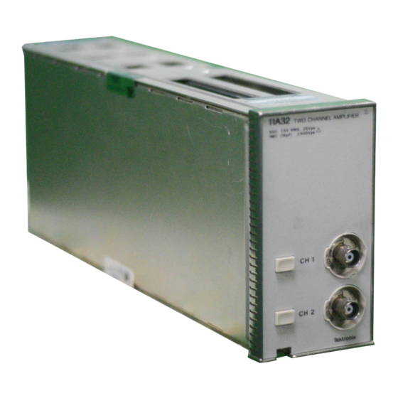
Two Channel Amplifier
Service Reference
The following servicing instructions are for use by qualified person-
nel only. To avoid personal injury, do not perform any servicing
unless you are qualified to do so. Refer to the Safety Summary
prior to performing any service.
INFORMATION at
CHANGE
Product Group 47
WARNING
rear
the
of this
manual.
Advertisement
Table of Contents

Related Manuals for Tektronix 11A32


Summary of Contents for Tektronix 11A32
- Page 1 Product Group 47 Two Channel Amplifier Service Reference WARNING The following servicing instructions are for use by qualified person- nel only. To avoid personal injury, do not perform any servicing unless you are qualified to do so. Refer to the Safety Summary prior to performing any service.
- Page 3 3000000 Sony/Tektronix, Japan 7000000 Tektronix Holland, NV, Heerenveen, The Netherlands Copyright D Tektronix, Inc., 1987. All rights reserved. Tektronix products are covered by U.S. and foreign patents, are registered trademarks. issued and pending. TEKTRONIX, INC., SCOPEMOBILE and Printed in U.S.A.
-
Page 4: Table Of Contents
Contents Section I-General Information Introduction ..........Plug-in to Mainframe Compatibility . - Page 5 Signal Flow ....l.t.1...t........_. Section S-Replaceable Parts Change Information Related Documentation rear of this manual lists the Tektronix part numbers for all Standard Accessories provided with rhis product. Manuals (Standard Accessories) 1 IA32 User’s Rcfwence Manual llA32 Service Reference...
- Page 6 l - 3 Installing a plug-in h a mainframe oscilloscope........Figure 1-I.
- Page 7 List of Tables ..............2-14 l l A 3 2 BandwidthTable .
- Page 8 Safety Summary manual where they apply, but may not appear in this summary. Terms In This Manual CAUTION Statements identify conditions or practices that could result in damagc to the equipment or other propwty. WARNING statements identify wnditions or practices that could result in personal injury or loss of life.
- Page 9 Warnings Power Source This product is intended to operate in a mainframe connected to a will not apply more than 250 V rms between the supply conductors or bctwccn &rounding conductor in the mainframe power cord, is essential for safe operation. Grounding This product is grounded through the grounding conductor of the mainframe power cord.
-
Page 10: Section I-General Information
The system bandwidth depends on the host mainframe. Details about bandwidth are. included in Part 4, Specificarion, of the User’s Reference Supplcmcnt, and in the Tektronix Corporate Catalog. Refer to rhe Tektronix Corporate Catalog for com- General Information - 1 lA32 Service Reference... - Page 11 Inspection Procedure shipped with the instrument to verify instrument per- formance. If you find damage or deficiency, contact your local Tektronix Firlcl Of- fice or representative. lnstalling and Removing the Plug-In To install the plug-in in any 11000~series oscilloscope mainframe: Set the mainframe ON/STANDBY switch to STANDBY to prevent damage to the instrument.
-
Page 12: Instrument Options
MAINFRAME Instrument Options includes two P6134 General Information- llA32 Service Kcfcrence... -
Page 13: Packaging For Shipment
Package and ship plug-in and mainframes separately. Attach a tag to the plug-in if it is shipped to a Tektronix or repair. Include the following information on the Name and address of the instrument owner;... - Page 14 and long inst;ument life. Operating Temperature Operate the plug-in where the ambient air temperature is between O0 and +50’ C. Store the plug-in unit in ambient temperatures from -40’ to + 75” C. After storage at temperatures outside the operating limits, allow the chassis to reach temperature range before applying power.
-
Page 15: Section 2 Checks And Adjustments
Section Checks and Adjustments This seclion wntain$ proccdurcs to check clecttical specifications and to manunlly set all internal adjustments. This procedure provides a logical sequence of cheek and adjustment steps, and is inlcnded to return the instrument to spccificd operation following repair, or as a part of a routine mnintcnancc program. -
Page 16: Plug-In Unit Installation And Removal
Plug-h Unit Installation and Removal To avoid insmrmeot dumage, set the mainframe ON/STANDBY switch to STANDBY be f or e installing or wmovi~lgplttg-in tmits. Initialized Setting At the beginning of most steps, the user is instructed to Initialize the instrument part of the setup. - Page 17 TABLE 2-1 Test Equipment Minimum Test Equipment Tektronix four-cornpart. TEKTRONIX TM SO4 Power Module. 250 MHZ to 1000 MHZ, E K T O N I Leveled variable Sine Wave amplitude, 50 kHz or Generator with a Generators TM 500~scrics 6 MHz rcfuence.
- Page 18 TABLE Z-1( cant) Test Equipment Minimum Examples of Description Test Equipment 50 R Termination 50 n; Tektronix Part 011-0049-01. Accuracy, within 2%; connectors, BNC. 510 R, 10% tolerance; Tektronix Part 303-0511-00. Resistor Insulated slot. Tektronix Part 003-0675-01. Alignment Tool (insulated slat) Holder for Ton;...
- Page 19 Procedure Power on the following test equipment, so that it is wnrtned up with the instrument to be tested. Power Supply Calibration Generator Leveled Sine Wave Generators Digital Voltmeter With the ON/STANDBY switch set to STANDBY, connect the mainframe to a suitable power source.
- Page 20 Part 2a - Examine/Adjust Step Response: ’ Standard Procedure The Amplifier high frequency peaking is adjusted so that the bandwidth is adequate Description and that the aberrations are not excessive. The Standard Procedure requires the use mainframe. If an 11402 mainframe is not available, use an 11401 to perform this procedure.
- Page 21 Step Response: Standard Procedure Examine Mainframe Step Response Setup Oscilloscope Mainframe Utility Instrument Options Scaling Waveform (Forced) u Source De== Trigger Source Description menu (center) Not used in this step. + Step Resp Rate o’clock o’clock Trig Level ,,,,,,,,,,,,,,,,....,..,..,,..,..,.. one division from left edge of graticulc Acquire Description Pos: horizontal graticule lint...
- Page 22 Standard Procedure Examine/Adjust Plug-h Step Response (Al RI 015,, Al R1025) Coaxial Cable Perform the following settings in the order listed: Remove the left side cover from the llA32. the I IA32 into Connect the 067-0681-01 Pulser to the CH I input connector. Connect a 50 R coaxial cable from the Calibration Generator High Amp1 Output connector to the Calibration Generator...
- Page 23 the previous Examine Mainframe Step Response procedure and cxaminc the plug-in’s contribution for aburations within 4.5% peak (2.25 divisions) and 7% peak-to-peak (3.5 divisions). DO NOT attempt to optimize the aberrations if they are within the stated limits. Proceed ADJUST-WI, RI015 on the Al Main board, 50 that the CH 1 aberrations arc within 4.5% peak (2.25 divisions) and 7% peak-to-peak (3.5 divisions).
- Page 24 Alternative Procedure Description and lhat the aberrations are not excessive. This procedure is used when neither the 11401 nor the 11402 mainframe is available. Performance is assured only for the particular plug-in and mainframe combination examined and adjusted in this procedure.
- Page 25 ‘ the point where B step just stans to appear on the lower pan of the positive-going edge. Oscilloscope Main Size Offset position step divisions the center horizontal graticulc lint Size: Fine amplitude display Checks and Adjuslments-11A32...
- Page 26 Part 2-Examine/Adjust Step Response: Standard Procedure Procedure a. WINE-that the displayed waveform aberrations arc less than 4.5% peak (0.225 division) and 7% peak-to-peak (0.35 division). DO NOT attempt to optimize the aberrations if they are within the stated limits. Proceed to within 4.5% peak (0.225 division) and 7% peak-to-peak (0.35 division).
-
Page 27: Part &Check Bandwidth
Part Description At SO kHz the Leveled Sine Wave Generator amplitude is scl for a displayed amplitude is checked for less than a 3 dB decrease. Specified performance of the ulur-in in all mainframes is sssurcd only if the nlun-in bandwidth, specified performance is assured only in mainframes of equal or lower bandwidth. - Page 28 Part 3-Check Bandwidth Procedure Perform this procedure for each Vertical Size listed in Table 2-2; then repeat for CH This procedure may require the use of more than one Leveled Sine Wave Generator to test all the frequencies listed in Table 2-2. If the Leveled Sine Wave Generator is not equipped with internal attenuators, then use two 10X Attcnualots at the plug-in unit input when setting amplitude.
- Page 29 Part 4-Check Enhanced Accuracy When disnlavcd. the Enhanced Accuraw svmbol (EAI indicates that the instrument is at its h&h&t &racy state. The in&‘mcnt sks’the time ambient temperature for use in maintaining the Enhanced For more information about the Enhanced Accuracy state, see Enhanced Accuracy Indicator in the mainframe User’s Rcfcrence manual.
- Page 30 Part 4-Enhanced Awlran/ Procedure Twenty minutes after power up, the instrument must twalibratc itself to achieve the Enhanced Accuracy state. Press the ENHANCED ACCURACY button. Another prompt then appears on the display. Press the ENHANCED ACCURACY button again. Self-calibration takes a couple of minutes. losing the Non-Volatile RAM dnta.
- Page 31 Part 5-Check DC Balance Description Refer to Table 2-3. Specification Setup the order listed. Limit Limit Procedure Perform this procedure for each channel. value Shift listed in Table 2-3 for each Vert Size xtting. If you are using the 11301 or 11302 mainframe, USC Vertical Cursors to help If you arc using the 13401 or 11402 mainframe, set Average N to ON and we Mean (whole zone) in the Measurement menu to help measure the tract position.
- Page 32 TABLE 2-3 0.093 10 V/div 0.063 6 3 0 0.065 3 3 0 0.095 0.103 2 Vldiv 0.073 0.085 0.115 0.095 0.5 V/div 0.065 0 . 1 0 3 0.2 V/div 0.073 0 . 1 1 5 0.1 V/div 0.085 50 mV/div 0.095 0.065...
-
Page 33: Part A-Check Enhnnccd Accuracy
Part 6-Check AV DC Accuracy Description The system AV DC Accuracy is checked using a precision Digital Voltmcler and a Power Supply. The system must be in Enha’wd Accuracy mode during this procedure. connect&a yet) (not connected yet) (not connected yet) the oscilloscope’s settings then perform the fallowing the order listed. - Page 34 Part &Check AV DC Accuracy a. If you use the 11301 or 11302 mainframe, then Select Vertical Cursors and position the cursors for readouts of Veti Ref = -30.0 V and Avert = 60.0 V. If you use the 11401 or 11402 mainframe, then set Average N to ON and use Mean zone) in the Measurements menu to help set the trace to the (whole...
- Page 35 Part 7-Check DC Offset Accuracy Description The system DC Offset is checked using a Precision Digital Voltmctcr snd B POWI The system must be in Enhanced Accuracy mode during lhis’.procedure. Refer to Table 2-S. Specification setup Digital Voltmeter 50 R Termination (not connected yet) (not connected yet) Center...
- Page 36 Part 7-Check DC Offset ACCU~~LY Procedure Perform this procedure for each channel. Note the position of the displayed trace (it should be near the center of the measure and set the trace position. If you are using the 11401 or 11402 mainframe, set Average N to ON and use Mean (whole zone) in the Measurement menn to help tneasure and set the trace position.
- Page 37 Section 3 This section contains information for performing preventive maintcnancc, corrective maintenance, testing and diagnostics. All support-related items in this manual are listed in Table 2-1. Preventive Maintenance breakdown and may improve instrument reliability. The severity of the environment to which the instrument is subjected determines the frequency of maintcnancc.
- Page 38 Preventive Exterior Loose dust accumulated on the outside of the instrument can br removed with a soft cloth or small brush. The brush is particularly useful for dislodging dirt in and around the side-shield ventilation hales and front-panel switches. Remove the side shields before cleaning them.
-
Page 39: Correctivemaintenance
1. Instrument type 2. Instrument serial “umber A description of Ihe part (if clccttical, i”cludc circuit number) 4. Tektronix part “umber Static-Sensitive Device Classification This instrument contains electrical components that arc susccptiblc to damage from static discharge. Table 3-1 gives relative susceptibility of various classes of wmicon- Minimize handling of static-sensitive components. - Page 40 Corrective Maintenance 6. Pick up components by the body, never by the ICWJS. 7 . Do not slide the components over any surface. 8. Avoid handling components in areas that have a floor or work-surface coveting capable of generating a static charge. Relative Susceptibility to Damage From Static Discharge Relative Semiconductor Classes...
-
Page 41: Removingand Replacing Frus
Removing and Replacing FRUs To avoid instmment damage, set the mainframe ONISTANL~~Y switch to STANDRY and rernow the plug-it1 from the rnuinjiarne To determine lhc location of a FRW, refer to Figure 3-1. The side shields will have to be removed to gain access to the circuit boards and The exploded-view drawing associaled wilh the Replaccahlc Partr list may be helpful in the disassembly procedures that follow. - Page 42 Maintenance HOUSEKEEPER EPROM AMP 2 ATTENUATOR AMP 1 FRONT PANEL PROCESSOR BOARD JUMPER BLOCKS (3) NUT BLOCKS (2) Figure 3-1. Field Replaceable Units (FRU) locator and Maintenance- HA32 Service Reference...
-
Page 43: Housekeeper Integrated Circuit ("Slam-Pack" 10)
Semiconductor FRU Removal Observe all the ~speciol prcamtiom tnerztiomd under the head- ing, “Static-Sensitive Device Churi~cntiotz, ” in this sectiort Housekeeper integrated Circuit (“Slam-Pack” ICs) The Housekeeper IC (A I UCflO) is indexed to its socket by a bw:vclcd corner, a$ shown in Figure 3-2. -
Page 44: Amplifierhybrids
Corrective Maintensncc END TABS BEVEL CLIP MATING RECESSES INDEX SPRING EXPLODED VIEW OF BE-PIN SLAM PACK HOUSEKEEPER IC INDEX EPROM PROCESSOR + INDEX MICROPROCESSOR INTEGRATED CIRCUITS F i g u r e 3 - 2 . SemiCOndUCtor i n d e x i n g d i a g r a m . Amplifier Hybrids and gives disassembly and replacement instructions. - Page 45 Corrective Maintcnancc elastomer, and the Hypcon contacts under light for dust, hair, lint, etc. I I - Blow or vacuum clean, while dusting the surface with a small clean brush. If the hybrid and elastomer contact holder are contaminated, clean them by flushing or spraying with alcohol and wcn dty at + 50”...
- Page 46 EXPLODED VIEW OF HYPCON CONNECTOR 3 PLASTIC FRAME REGISTRATION PINS ELASTOMER (CONTACT HOLDER) MICROCIRCUIT STIFFENER/ HEAT SINK CROSS SECTION VIEW OF HYPCON CONNECTOR ELASTOMER CONTACT HOLDER CONDUCTOR Figure 3-3. Hypcon assembly removal and replacement. Maintenance- llA32 Service...
- Page 47 DISASSEMBLY AND REMOVAL Unscrew and remove the 4 screw/washer assemblies. corner with tweezers lifting up. Do not touch the gold-plated contacts with your fingers, REASSEMBLY AND REPLACEMENT Grasp a corner of the elastomer with tweezers and place it into plastic frame. Align keyed corner of elastomer with keyed corner of plastic frame.
-
Page 48: Eprom Ic
EPROM IC Do not mnow the label afied to the top of EPROMs. Removing this label will allow light into the chip, and mny catrs~pat?ial mxttre of irr dm to Fig. 3-l for the localion of this IC.) Remove the EPROM IC as follows: 1. - Page 49 Corrective Maintcnancc Processor IC The Pro~cssor IC (AlU700) is located on the Al Main board. Refer to Figure 3-I for its location. The EPROM IC is mounted on top of lhe Processor JC. Remove the Processor IC as follows: Remove the EPROM JC. Follow the removal instruclions given in Ihe prcocd- Position the pliers around the outside of the IC.
- Page 50 Figure 3-4. IC Insertion-Extraction Pliers. Maintenance-llA32 Sctvice Reference 3-14...
-
Page 51: Circuit Board And Attcnualor Fru Removal
Circuit Board and Attenuator FRU Removal How to Remove the Front Panel Unhook lhe relur” spring from the ~CIE~SC bar, a”d se1 il aside. Pull the rclcasc bar as far out of lhe instrument as it will come, und leave it i” position. - Page 52 How to Remove an Attenuator The CH 1 and CH 2 Attenuators are identical. Remove lhe front panel as outlined in “How to Remove Unplug Ihe cahlc that connects the attenuaror to the Al Main board. Use a Tot% T-S screwdriver to remove the two screws from the component side of the Al Main board that the subject attenuator (refer to Fig.
- Page 53 SINGLE CHANNEL SHOWN ATTENUATOR MOE STRIPS (2) MOE HOLDER CIRCUIT Figure 3-5. Locatlon of screws and parts for removal of an attenuator. Remove the Board Al Main Unplug the connector(s) from the Front-Panel board(s) at the AL Main board. a Torx T-8 screwdriver to remove the screws attaching Ihc altcnwtors lo the A’l Main board.
- Page 54 Corrective Mainrenancc (MOE) strips and holders, 8 . Use a Torx T-15 screwdriver to remove the scrws that attach the heat sink bracket to the Al Main board. 9 . Use a Torx T-IO scrcwdtiver to remove the five scrws and nut blocks that se- cure the Al Main board to the top and bottom frameas.
- Page 55 Use a Torx T-1,5 scrcwdtiver to start the screws fastening Ihe heat sink bracket to the Al Main board. Tighten the screws that you installed in steps 3, 4, and 5. MOE slrips i” the holders as shown in Figure 3-5. Slide the front panel and attenuator assembly into position, being careful no1 lo dislodge the MOE strips or holders.
-
Page 56: Programming The Unit Identification
Programming The Unit Identification The Unit Identification (UID) is identical to the instrument’s stored in NV RAM. It is necessary to enter this number if the Al Main board is replaced or if data in NV RAM becomes corrupted. If confirmation only of the UID is needed, then u5c: the following procedure except skip step 4. -
Page 57: Multi-Pinconnectors
Multi-Pin Connectors Pin I OII a multi-pin connector is designated with a triangle (or arrowhcad) on the holder. A syuarc pad on the circuit board denotes pin 1. When a connection is made to a circuit board, the indexing of the triangle on the multi-pin holder is detcr- mined by the square pad. -
Page 58: Troubleshooting
Troubleshooting Diagnostic Troubleshooting This section provides the information necessary lo troubleshoot a faulty instrument to the Field Replaceable Unit (FRU) level. FRUs are circuit boards, attenuator integrated circuits that modules, and or hybrids are replaceable without soldering. The primary means for troubleshooting is lo use the error index code output from the Diagnostics or Self-Tests and cross-reference them to the suspect FRU(s) in the FRU Guide tables. - Page 59 If the plug-in Kernel Tests dctcct a faull, then the CH 2 LED is flashed eight times to display a fault code. Each time the CH 2 LED turns on, count Chc Refer to the riming diagram in Figure 3-8 for an cxamplc LED fault code. Figure 3-8.
-
Page 60: Self-Tcstextended Diagnostics
3 . The Housekeeper IC Test verifies lhe functionality the Housekeeper IC. The Housekeeper IC performs many ‘housekeeping’ chores of the amplifier, including channel sequencing, refreshing the analog control voltage system, latching amplifier step gain settings, and the communications with the main- frame. -
Page 61: New Configuration Calibration
Front-panel timtroh ztre active dutiny the Self-Test scqucnce and any disturbance Self-Test Diagnostics test the following: Attenuator relay driver Probe coding Calibration constant checksums Calibration constant values Signal path Using the Self have run, any resultant error index codes Tests/Extended agnostics menu. -
Page 62: Abbreviations Of Fru Names
Troubleshooting Abbreviations of FRU Names All boards are listed here with the abbreviation used in the FRW tables below: Abbreviation Main Main board Front Front Panel board Abbreviations of Component and Module Names All active components and modules are listed here with the abbreviation used in Ihe Abbreviation Designator Processor... - Page 63 This table lists the error messaycs possible in the Self-Tests and Extcndcd Dingnos~ tics. Error Index Suspect Module, Hybrid, or IC FRU(s) Main Main Main Main Amp, HK Main Main Att, Amp, HK Interconnections are not listed but should he considered as possible problem This table lists the error messagcs resulting from Enhanced Accuracy.
-
Page 64: Section 4-Theory Of Operation
Section Theory of Operation This section describes and illuslra~es (refer to Fig. 4-l) the plug-in block diagram; including signal flow and control flow. This section also discusses the power supplies Block Diagram Description Signal Flow The CH 1 and CH 2 Amplifier circuits are identical, therefore this section dcscrihcs only the CH 1 Amplifier. - Page 65 Calibration Reference Voltage CH 1 Aux Signal Trigger Signal Display Signal CH 2 Aux Signal Amplifier Probe Offset Variable Gain, Offset Overload Sense, Probe Data 3andwidth Control, Conversion EPROM Housekeeper Channel Switch Sequence Al Main Board Figure 4-1. 1 IA32 Two-Channel Ampllfler.
-
Page 66: Controlflow
display Ihe sdec~ed channel and turn on that channel’s respective front-panel LED). Control Flow Under the control of the mainframe’s channel swilch sequencing signals, rhc Housc- keeper sequentially turns a channel on or off. The MPU and Housckucpcr contrid Power The mainframe supplies 811 the power 10 lhe plug-in. -
Page 67: Section S-Replaceable Parts
Se c t i on 5 REPLACEABLE PARTS ABBREVIATIONS Par t s... - Page 68 Ci t y. St at e . TEXTRON I NC I L 61108 1818 CHRI STI NA ST SEM S PRODUCTS "NI T 17301 RI f f i El AND CA 91411 15201 BURBANK BLYD SUI TE C NW S TEKTRON X I NC OR 97077...
- Page 70 070- 6782- K...
Need help?
Do you have a question about the 11A32 and is the answer not in the manual?
Questions and answers