Table of Contents
Advertisement
Quick Links
Smart encoders & actuators
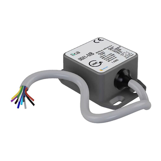
IXM1
IXM2
• 1-axis and 2-axis inclinometers
• MODBUS RTU interface (RS-485)
• Resolution down to 0.01°
• Robust die cast housing with IP67 protection rate
• Operating temperature -40°C +85°C
Suitable for the following models:
• IXM1-MB...
• IXM2-MB...
Lika Electronic
User's guide
•
Tel. +39 0445 806600
Version RS-485
Table of Contents
•
info@lika.biz
12
14
15
18
22
25
35
59
66
•
www.lika.biz
8
Advertisement
Table of Contents

Subscribe to Our Youtube Channel
Related Manuals for Lika IXM1-MB Series


Summary of Contents for Lika IXM1-MB Series
-
Page 1: Table Of Contents
1 Safety summary • IXM2-MB... 2 Identification 3 Mechanical installation 4 Electrical connections 5 Quick reference 6 MODBUS® interface 7 Programming parameters 8 Programming examples 9 Default parameters list Lika Electronic • Tel. +39 0445 806600 • info@lika.biz • www.lika.biz... - Page 2 Tous droits réservés. This document and information contained herein are the property of Lika Electronic s.r.l. and shall not be reproduced in whole or in part without prior written approval of Lika Electronic s.r.l. Translation, reproduction and total or partial modification (photostat copies, film and microfilm included and any other means) are forbidden without written authorisation of Lika Electronic s.r.l.
-
Page 3: General Contents
General contents User's guide................................. 1 General contents............................. 3 Subject Index..............................6 Typographic and iconographic conventions....................7 Preliminary information..........................8 Glossary of MODBUS terms.......................... 9 1 Safety summary..........................12 1.1 Safety....................................12 1.2 Electrical safety................................12 1.3 Mechanical safety..............................13 2 Identification............................14 3 Mechanical installation........................15 3.1 Overall dimensions (Figure 1)..........................15 3.2 Installation (Figure 2 and Figure 3)........................16 3.3 Orientation of the axis............................17... - Page 4 7 Programming parameters......................... 35 7.1 Modbus table................................35 7.2 Parameters available..............................36 7.2.1 Description of the registers........................36 X angle [0001 hex]............................36 Y angle [0002 hex]............................37 180 angle [0003 hex]............................37 360 angle [0004 hex]............................37 Temperature [0005 hex]..........................38 Status [0006 hex]..............................38 Y-Angle Err.Rng.High............................39 Y-Angle Err.Rng.Low............................39 X-Angle Err.Rng.High............................39 X-Angle Err.Rng.Low............................39 Y-Angle Err.USER Rng.High........................39...
- Page 5 7.3 Exception response and codes..........................56 8 Programming examples........................59 8.1 Reading the Status [0006 hex] register......................59 8.2 Reading the first five registers in the table....................59 8.3 Setting the Filter [000F hex] register........................59 8.4 Setting the Baud rate [000A hex] register......................60 8.5 Setting the Baud rate [000A hex] register......................60 8.6 Setting the Node address [000D hex] register....................60 8.7 Setting the Node address [000D hex] register....................60...
-
Page 6: Subject Index
Subject Index ResetDev [0034 hex]............55 1-Axis Mode...............40 1-Axis NVM.Error..............40 Status [0006 hex].............38 180 angle [0003 hex].............37 Stop bits [000C hex]............42 Store all [0032 hex]............54 2-Axis Mode...............40 2-Axis NVM.Error..............40 Temperature [0005 hex]..........38 TermRes [000E hex]............43 360 angle [0004 hex].............37 X angle [0001 hex]............36 X inversion [0017 hex]...........47 Baud rate [000A hex]............40 X offset [0016 hex]............47... -
Page 7: Typographic And Iconographic Conventions
In this guide, to make it easier to understand and read the text the following typographic and iconographic conventions are used: parameters and objects both of Lika device and interface are coloured in GREEN; • alarms are coloured in RED;... -
Page 8: Preliminary Information
Preliminary information This guide is designed to provide the most complete information the operator needs to correctly and safely install and operate the IXM series inclinometers with MODBUS RTU (RS-485) interface. Inclinometers are devices designed to measure the levelling and pitch and roll angles for motion control or safety purposes. -
Page 9: Glossary Of Modbus Terms
Glossary of MODBUS terms MODBUS, like many other networking systems, has a set of unique terminology. Table below contains a few of the technical terms used in this guide to describe the MODBUS interface. They are listed in alphabetical order. Address field It contains the Slave address. - Page 10 The function code field of a MODBUS data unit is coded in one byte. Valid codes are in the range of 1 ... 255 decimal (the range 128 – 255 is reserved and used for exception responses). Function code "0" is not valid. Lika devices only implement public function codes. Holding register In the MODBUS data model, a Holding register is the output data.
- Page 11 The Protocol Data Unit (PDU) is the MODBUS function code and data field. It is packed together with the Address Field and the CRC (or LRC) to form the Modbus Serial Line PDU. The MODBUS protocol defines three PDUs. They are: MODBUS Request PDU, mb_req_pdu •...
-
Page 12: Safety Summary
• elsewhere in this manual violates safety standards of design, manufacture, and intended use of the equipment; Lika Electronic assumes no liability for the customer's failure to comply • with these requirements. 1.2 Electrical safety Turn OFF the power supply before connecting the device;... -
Page 13: Mechanical Safety
IXM1 and IXM2 MODBUS® - minimize noise by connecting the shield and/or the connector housing and/or the frame to ground. Make sure that ground is not affected by noise. The connection point to ground can be situated both on the device side and on user’s side. -
Page 14: Identification
Information is listed in the delivery document too. Please always quote the order code and the serial number when reaching Lika Electronic for purchasing spare parts or needing assistance. For any information on the technical characteristics of the product refer to the technical catalogue. -
Page 15: Mechanical Installation
IXM1 and IXM2 MODBUS® Mechanical installation WARNING Installation and maintenance operations must be carried out by qualified personnel only, with power supply disconnected. Mechanical components must be in stop. For any information on the mechanical data and the electrical characteristics of the inclinometer please refer to the technical catalogue. -
Page 16: Installation (Figure 2 And Figure 3)
IXM1 and IXM2 MODBUS® 3.2 Installation (Figure 2 and Figure 3) Figure 2 - Installation Install the inclinometer as shown in Figure 2 and Figure 3: tighten the flange 2 using four M3 x 6 min. DSP screws 1; • max. -
Page 17: Orientation Of The Axis
IXM1 and IXM2 MODBUS® 3.3 Orientation of the axis WARNING Always comply with the mounting positions indicated in Figure 3 according to the model to be installed or the selected operational mode (1-axis inclinometer or 2-axis inclinometer). 1 axis 2 axes Figure 3 - Mounting positions NOTE 2-axis inclinometers can be mounted also upside down as shown in the Figure. -
Page 18: Electrical Connections
IXM1 and IXM2 MODBUS® Electrical connections WARNING Electrical connections must be carried out by qualified personnel only, with power supply disconnected. Shaft and mechanical components must be in stop. For any information on the mechanical data and the electrical characteristics of the inclinometer please refer to the technical catalogue. -
Page 19: M12 5-Pin Connector (Ixm
IXM1 and IXM2 MODBUS® 4.2 M12 5-pin connector (IXM...M...) M12 5-pin male connector A coding (frontal view) Description Not used +10Vdc +30Vdc power supply voltage 0Vdc power supply voltage Modbus A (RS-485+) (D1) Transceiver terminal 1, V1 Voltage (V1 > V0 for binary 1 [OFF] state) Modbus B (RS-485-) (D0) Transceiver terminal 0, V0 Voltage (V0 >... -
Page 20: Supply Voltage And Current Consumption
IXM1 and IXM2 MODBUS® The “Common” circuit (Signal and optional Power Supply Common) must be connected directly to the protective ground. This connection has to be done preferably in a single point of the bus. Generally, choose a point which is close to the Master device. To minimize reflections from the RS-485 BUS cable ends, place an LT (Line Termination) close to each one of the two ends. -
Page 21: Line Termination
IXM1 and IXM2 MODBUS® 4.7 Line termination For complete information refer to the “4.3 Wiring scheme” section on page 19. 4.8 Setting the baud rate For complete information refer to the “5.2 Setting the baud rate” section on page 23. 4.9 Setting the parity For complete information refer to the “5.3 Setting the parity”... -
Page 22: Quick Reference
1 or 2 bits (“Modbus over serial line specification and implementation guide V1.02” protocol requires 2 stop bits when the parity check is disabled); if required, set the node address; the default value set by Lika Electronic at • Node address [000D hex] factory set-up is “100”... -
Page 23: Setting The Baud Rate
IXM1 and IXM2 MODBUS® 5.2 Setting the baud rate The baud rate set at factory is “19,200 bits per second” (value 4). If you need to Baud rate [000A hex] change it, set a value between “1” and “5” in the Modbus register. -
Page 24: Measured Values
IXM1 and IXM2 MODBUS® 5.6 Measured values Once the inclinometer is configured to operate in the Modbus network it is possible to read the measured angles by accessing the Modbus table of the device. Use the Read Holding Registers (CMD code 0x03 hex) request frames. 5.6.1 Single-axis inclinometers 180 angle [0003 hex] The measured angle is available reading the registers... -
Page 25: Modbus® Interface
IXM1 and IXM2 MODBUS® MODBUS® interface Lika inclinometers are Slave devices and implement the MODBUS application protocol (level 7 of OSI model) and the “Modbus over Serial Line” protocol (levels 1 & 2 of OSI model). For any further information or omitted specifications please refer to “Modbus Application Protocol Specification V1.1b3”... -
Page 26: Modbus Frame Description
IXM1 and IXM2 MODBUS® 6.2 MODBUS frame description The Modbus application protocol defines a simple Protocol Data Unit (PDU) independent of the underlying communication layers: Function code Data MODBUS PDU The mapping of Modbus protocol on a specific bus or network introduces some additional fields on the Protocol Data Unit. -
Page 27: Transmission Modes
The transmission mode and the serial port parameters must be the same for all devices on a Modbus Serial Line. All devices must implement the RTU mode, while the ASCII mode is an option. Lika devices only implement RTU transmission mode, as described in the following section. -
Page 28: Rtu Transmission Mode
IXM1 and IXM2 MODBUS® 6.3.1 RTU transmission mode When devices communicate on a Modbus serial line using the RTU (Remote Terminal Unit) mode, each 8-bit byte in a message contains two 4-bit hexadecimal characters. Each message must be transmitted in a continuous stream of characters. - Page 29 IXM1 and IXM2 MODBUS® The following drawing provides a description of the RTU transmission mode state diagram. Both “Master” and “Slave” points of view are expressed in the same drawing. Initial State Idle Transition from state needs an interval of at least •...
-
Page 30: Modbus Addresses
Reserved function codes are not available for public use. 6.4.1 Implemented function codes Lika Modbus inclinometers only implement public function codes, they are described hereafter. 03 Read Holding Registers FC = 03 (03 hex) ro This function code is used to READ the contents of a contiguous block of holding registers in a remote device;... - Page 31 IXM1 and IXM2 MODBUS® read must be in the range of 1 to 125 (0x7D). This limit guarantees that the maximum length of the frame for response messages is always less than or equal to 252 bytes. The starting address plus the number of registers to read cannot go beyond the Modbus table, otherwise, an error condition is detected and an error message with exception code 0x02 (ILLEGAL DATA ADDRESS, refer to the “7.3 Exception response and codes”...
- Page 32 IXM1 and IXM2 MODBUS® Exception code 1 byte 01 or 02 or 03 or 04 Error check CRC 2 bytes Frame dependent Here is an example of a request to read the first five registers in the table, i.e. X (X angle [0001 hex] Y angle [0002 hex] and Y values of the 2-axis mode...
-
Page 33: Write Single Register
IXM1 and IXM2 MODBUS® 06 Write Single Register FC = 06 (06 hex) This function code is used to WRITE a single holding register in a remote device. The Request PDU specifies the address of the register to be written. Registers are addressed starting at zero. -
Page 34: Modbus Function Codes Not Supported
IXM1 and IXM2 MODBUS® Here is an example of a request to change the digital filter of the inclinometer (Filter [000F hex] register) to value “50” (0x32 hex). Request Response Field name (Hex) Field name (Hex) Slave address Slave address Function Function Register address Hi... -
Page 35: Programming Parameters
IXM1 and IXM2 MODBUS® Programming parameters 7.1 Modbus table Immediately ADD (dec) ADD (hex) Register Data type Description Default store effective 2D inclin. X axis angle X angle [0001 hex] 0001 0x0001 SIG16 [-60.00° … +60.00°] 2D inclin. Y axis angle 0002 0x0002 Y angle [0002 hex]... -
Page 36: Parameters Available
IXM1 and IXM2 MODBUS® 0051 0x0033 Reload all [0033 hex] UNS16 Load factory configuration ResetDev [0034 hex] 0052 0x0034 UNS16 Reboot device This register can be accessed for reading and writing operations in both single axis and dual axis inclinometers This register can be accessed for reading and writing operations in dual axis inclinometers only 7.2 Parameters available... -
Page 37: Y Angle [0002 Hex]
IXM1 and IXM2 MODBUS® X range [0018 hex] The value in the register defines the maximum and minimum values for the measured angle. X angle [0001 hex] X offset [0016 hex]) * X inversion [0017 hex] RAW-ANGLE Y angle [0002 hex] [Register 3, Signed16, ro] Y angle [0002 hex] register stores the Y tilt angle of the dual-axis mode. -
Page 38: Temperature [0005 Hex]
IXM1 and IXM2 MODBUS® angle [0004 hex] register is a RO register. The response time depends on the (Filter [000F hex] setting of the digital filter register). 360 angle [0004 hex] X offset register value is affected by the content of the [0016 hex] X inversion [0017 hex] X range [0018 hex]... -
Page 39: Y-Angle Err.rng.high
IXM1 and IXM2 MODBUS® Bit 12 Y-Angle Err.Rng.High The detected tilt angle for the Y axis of the inclinometer is over the higher limit value of the measuring range defined by factory default. This status bit is valid only for dual-axis inclinometers. Bit 11 Y-Angle Err.Rng.Low The detected tilt angle for the Y axis of the inclinometer is below the lower limit... -
Page 40: X-Angle Err.user Rng.low
IXM1 and IXM2 MODBUS® Bit 5 X-Angle Err.USER Rng.Low The detected tilt angle for the X axis of the inclinometer has reached a value less X range than the lower limit of the user-defined measuring range set in the [0018 hex] register. -
Page 41: Parity [000B Hex]
IXM1 and IXM2 MODBUS® 19,200 bit/s 38,400 bit/s To be effective a new baud rate setting must be saved to the NVM and then the -ResetDev [0034 hex] inclinometer must be rebooted (software reset register or power off/on cycle). When the inclinometer restarts and initializes itself, the new baud rate value is loaded from the NVM and becomes effective. -
Page 42: Stop Bits [000C Hex]
IXM1 and IXM2 MODBUS® Stop bits [000C hex] [Register 13, Unsigned16, rw] Stop bits [000C hex] register allows to set the stop bit character used for the serial communication rules. The default setting is “1 stop bit” (when “2 = Parity [000B hex] Stop bits [000C Even parity”... -
Page 43: Termres [000E Hex]
IXM1 and IXM2 MODBUS® TermRes [000E hex] [Register 15, Unsigned16, rw] – STILL NOT IMPLEMENTED TermRes [000E hex] register allows the software activation or deactivation of the integrated resistor of the inclinometer for RS-485 differential BUS line termination. Line Termination integrated resistor is deactivated by the factory: TermRes [000E hex] the default value is “1 = OFF”. -
Page 44: Zero [0014 Hex]
IXM1 and IXM2 MODBUS® Filter [000F hex] Response time versus register value is shown in the following chart: X zero [0014 hex] [Register 21, Unsigned16, wo] X zero [0014 hex] register starts the auto computing function for the offset [0016 hex] X angle [0001 hex] value that sets the value to zero. -
Page 45: Preset [0015 Hex]
IXM1 and IXM2 MODBUS® X angle [0001 hex] Note that the value in the above expression includes the X inversion [0017 hex] current setting so the sign of the new value in the offset [0016 hex] register takes into account the current sign of the X axis. For X zero [0014 hex] this reason, always use the function after the activation of... - Page 46 IXM1 and IXM2 MODBUS® X offset [0016 hex] value for single-axis inclinometers is calculated as follows: X offset [0016 hex] [X preset [0015 hex] (360 angle [0004 hex] – offset [0016 hex] PREVIOUS X offset [0016 hex] value for dual-axis inclinometers is calculated as follows: X offset [0016 hex] [X preset [0015 hex]...
-
Page 47: Offset [0016 Hex]
IXM1 and IXM2 MODBUS® X offset [0016 hex] [Register 23, Signed16, rw] X offset [0016 hex] register stores the offset value applied to the X offset [0016 hex] measured raw X axis tilt of the inclinometer. The register value is a 2’s complement 16-bit integer fixed-point value with 0.01 deg X offset [0016 hex] resolution. -
Page 48: Range [0018 Hex]
IXM1 and IXM2 MODBUS® X inversion [0017 hex] initializes itself, the last saved register value is loaded X angle [0001 hex] from the NVM and used to calculate the measured value. X range [0018 hex] [Register 25, Signed16, rw] X range [0018 hex] register contains the user-defined range for detected tilt angle in the X axis of the inclinometer. -
Page 49: Y Zero [001E Hex]
IXM1 and IXM2 MODBUS® X range [0018 hex] register value is immediately effective just after the write single register command response frame is transmitted by the X range [0018 hex] inclinometer. The value can be saved to the NVM by means Store all [0032 hex] of the command to retain the new value after turning off... -
Page 50: Y Preset [001F Hex]
IXM1 and IXM2 MODBUS® Store all [0032 hex] saved to the NVM by means of the command to retain the new value after turning off the power supply of the inclinometer. When the Y offset [0020 hex] inclinometer restarts and initializes itself, the last saved register value is loaded from the NVM and used to calculate the measured angle [0002 hex] value. -
Page 51: Y Offset [0020 Hex]
IXM1 and IXM2 MODBUS® Y offset [0020 hex] inclinometer restarts and initializes itself, the last saved register value is loaded from the NVM and used to calculate the measured angle [0002 hex] value. Y preset [001F hex] register is available only for dual-axis inclinometers. Y offset [0020 hex] [Register 33, Signed16, rw] Y offset [0020 hex]... -
Page 52: Y Range [0022 Hex]
IXM1 and IXM2 MODBUS® Y inversion [0021 hex] register is available only for dual-axis inclinometers. Y range [0022 hex] [Register 35, Signed16, rw] Y range [0022 hex] register contains the user-defined range for detected tilt angle in the X axis of the inclinometer. IXM inclinometers are factory configured to a default measuring range (e.g.: ±30 deg or ±60 deg) depending on the model. -
Page 53: Devcode [0028 Hex]
IXM1 and IXM2 MODBUS® Y range [0022 hex] register is available only for dual-axis inclinometers. DevCode [0028 hex] [Register 41, Unsigned16, ro] DevCode [0028 hex] register contains the factory identification code for the specific model of the IXM inclinometer. This information is useful for any DevCode [0028 hex] technical support question. -
Page 54: Prodfw [002E Hex]
IXM1 and IXM2 MODBUS® ProdFw [002E hex] [Register 47, Unsigned16, ro] ProdFw [002E hex] register contains the firmware version of the inclinometer. This information is useful for any technical support question. ProdFw [002E hex] register is a RO register. Store all [0032 hex] [Register 51, Unsigned16, wo] Store all [0032 hex] register allows to save the configuration of the... -
Page 55: Resetdev [0034 Hex]
IXM1 and IXM2 MODBUS® [0033 hex] register. When the restoring factory configuration process ends, the inclinometer sends the response message for the single register command. Reload all [0033 hex] register is a WO register. A read holding registers Reload all [0033 hex] command will always return a zero value for the register. -
Page 56: Exception Response And Codes
IXM1 and IXM2 MODBUS® 7.3 Exception response and codes When a Client device sends a request to a Server device it expects a normal response. One of four possible events can occur from the Master's query. If the Server device receives the request without a communication error •... - Page 57 IXM1 and IXM2 MODBUS® NOTE Please note that here follows the list of the exception codes indicated by MODBUS but not necessarily supported by the manufacturer. MODBUS Exception codes Code Name Meaning ILLEGAL FUNCTION The function code received in the query is not an allowable action for the server.
- Page 58 IXM1 and IXM2 MODBUS® ACKNOWLEDGE Specialized use in conjunction with programming commands. The server has accepted the request and is processing it, but a long duration of time will be required to do so. This response is returned to prevent a timeout error from occurring in the client.
-
Page 59: Programming Examples
IXM1 and IXM2 MODBUS® Programming examples Hereafter are some examples of both reading and writing parameters. All values are expressed in hexadecimal notation. IXM1 inclinometer is installed (1 axis mode) The Master device is set up as follows: 19,200 bit/s, Even parity, 1 stop bit; the Node Address is set to factory default = “100”... -
Page 60: Setting The Baud Rate [000A Hex] Register
IXM1 and IXM2 MODBUS® 8.4 Setting the Baud rate [000A hex] register Request Baud rate [000A hex] Request of the Master to set the register to the sixth value (it does not exist!) 00 0A 00 06 20 3F Response 20 3F A error occurred while executing the write single register command: exception Baud rate [000A hex]... -
Page 61: Activating The Inversion In The X Inversion [0017 Hex] Register
IXM1 and IXM2 MODBUS® 8.8 Activating the inversion in the X inversion [0017 hex] register Request X inversion Request of the Master to activate the inversion (“2 = ON”) in the [0017 hex] register (please always activate the axis inversion option before the zero or preset command;... -
Page 62: Reading The 180 Angle [0003 Hex] And 360 Angle [0004 Hex] Registers
IXM1 and IXM2 MODBUS® 8.12 Reading the 180 angle [0003 hex] 360 angle [0004 hex] registers Request 180 angle [0003 hex] 360 angle Request of the Master to read the [0004 hex] registers 00 03 00 02 3D FE Response FD 86 8A 26 F9 CA 180 angle [0003 hex]... -
Page 63: Reading The 180 Angle [0003 Hex] And 360 Angle [0004 Hex] Registers
IXM1 and IXM2 MODBUS® 8.16 Reading the 180 angle [0003 hex] 360 angle [0004 hex] registers Request 180 angle [0003 hex] 360 angle Request of the Master to read the [0004 hex] registers by using wrong communication settings 00 03 00 02 3D FE Response... -
Page 64: Reading The Last Fifteen Registers In The Table
IXM1 and IXM2 MODBUS® 8.19 Reading the last fifteen registers in the table Request Request of the Master to read the last fifteen registers in the table starting from DevCode [0028 hex], so the last register to be read will be the register register 0037 hex 00 28... - Page 65 IXM1 and IXM2 MODBUS® 180 angle [0003 hex] > 180 angle = 0x1194 = +45.00 deg CLAMPED VALUE 360 angle [0004 hex] > 360 angle = 0x14C6 = 53.18 deg Temperature [0005 hex] > Temperature = 0x001C = +28°C Status [0006 hex] >...
-
Page 66: Default Parameters List
IXM1 and IXM2 MODBUS® Default parameters list Registers list and address Default value Baud rate [000A hex] 4 = 19,200 Parity [000B hex] 2 = Even Stop bits [000C hex] 1 = 1 stop bit Node address [000D hex] TermRes [000E hex] Filter [000F hex] X zero [0014 hex] X preset [0015 hex]... - Page 67 This page intentionally left blank...
- Page 68 Ce dispositif doit être alimenté par un circuit de Classe 2 ou à très basse tension ou bien en appliquant une tension maxi de 30Vcc. Voir le code de commande pour la tension d'alimentation. Lika Electronic Via S. Lorenzo, 25 • 36010 Carrè (VI) •...
Need help?
Do you have a question about the IXM1-MB Series and is the answer not in the manual?
Questions and answers