Table of Contents
Advertisement
Quick Links
Smart encoders & actuators
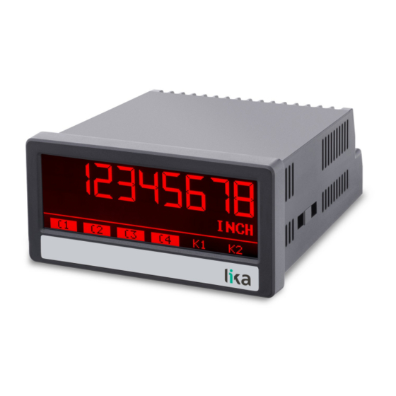
LD220
• Touch-screen indicator for SSI encoders
• For 10 to 32 bit singleturn and multiturn encoders with SSI
interface
• Operation as Master or Slave
• Analogue, serial, relay and control outputs
• DC / AC power supply: 18÷30Vdc or 115÷230Vac
Suitable for the following models:
LD220-P8-...
•
LD220-PM-...
•
Lika Electronic
User's guide
•
Tel. +39 0445 806600
General Contents
Preliminary information
1 - Safety summary
2 - Identification
3 - Mounting instructions
4 - Electrical connections
5 - Display and touch screen
6 – Menus and parameters
7 - Appendix
8 - Modbus RTU Interface
9 - Parameters / serial codes
•
info@lika.biz
11
13
15
16
18
29
34
86
87
91
•
www.lika.biz
Advertisement
Table of Contents

Related Manuals for Lika LD220


Summary of Contents for Lika LD220
- Page 1 User's guide Smart encoders & actuators LD220 • Touch-screen indicator for SSI encoders • For 10 to 32 bit singleturn and multiturn encoders with SSI interface • Operation as Master or Slave • Analogue, serial, relay and control outputs • DC / AC power supply: 18÷30Vdc or 115÷230Vac...
- Page 2 Tous droits réservés. This document and information contained herein are the property of Lika Electronic s.r.l. and shall not be reproduced in whole or in part without prior written approval of Lika Electronic s.r.l. Translation, reproduction and total or partial modification (photostat copies, film and microfilm included and any other means) are forbidden without written authorisation of Lika Electronic s.r.l.
-
Page 3: Table Of Contents
General contents General contents..............................3 Subject index............................... 8 Typographic and iconographic conventions....................10 Preliminary information..........................11 Operational modes..................................11 Functional diagram..................................12 1 - Safety summary............................13 1.1 Safety......................................13 1.2 Electrical safety..................................13 1.3 Mechanical safety................................13 2 - Identification.............................. 15 3 - Mounting instructions..........................16 3.1 Overall dimensions................................16 3.2 Installation.....................................17 3.3 Cleaning, maintenance and service notes........................17... - Page 4 Encoder resolution.................................41 Bit per revolution................................41 Data format..................................41 Baud rate.....................................42 High bit....................................42 bit....................................42 Direction....................................42 Error bit....................................43 Error polarity..................................43 Encoder supply.................................43 6.3.1 Reading the SSI data..............................44 6.3.2 Internal processing and calculation of SSI data....................45 6.3.2.1 Checking the error bit..........................45 6.3.2.2 Data conversion..............................46 6.3.2.3 Data splitting..............................47 6.3.2.4 Considering SSI zero position........................48 6.3.2.5 Checking the direction of rotation......................49...
- Page 5 Output lock 1..................................63 Start up delay 1 (s)................................64 Event color 1..................................64 6.8 Preselection 2 menu................................65 Source 2....................................65 Mode 2....................................65 Hysteresis 2..................................65 Pulse time 2 (s)................................65 Output target 2................................65 Output polarity 2................................66 Output lock 2..................................66 Start up delay 2 (s)................................66 Event color 2..................................66 6.9 Preselection 3 menu................................67 Source...
- Page 6 6.13 Command menu................................76 Input 1 action...................................76 Input 1 config...................................78 Input 2 action...................................78 Input 2 config...................................78 Input 3 action...................................78 Input 3 config...................................78 6.14 Display menu..................................79 Source single..................................79 Source dual top................................79 Source dual down................................79 Large display..................................79 Start display..................................80 Color.......................................80 Brightness (%)..................................80 Contrast....................................81 Screen saver (s)................................81 Up-date-time...
- Page 7 9.11 Analog menu..................................95 9.12 Command menu................................95 9.13 Display menu..................................96 9.14 Linearization menu................................96 9.15 Serial codes of commands............................98...
-
Page 8: Subject Index
Subject index Input 2 config..............78 Input 3 action..............78 Additive value..............54 Input 3 config..............78 Analog end................74 Analog format..............74 Analog gain (%)..............75 Large display..............79 Analog offset..............75 Linearization mode............39 Analog source..............74 Low bit..................42 Analog start................74 Average filter..............59 MODBUS................73 Mode..................41 Baud rate................42 Mode 1..................61 Bit per revolution.............41 Mode 2..................65 Brightness (%)..............80... - Page 9 Scale units..............54, 58 Source dual down............79 Screen saver (s)..............81 Source dual top..............79 Serial baud rate..............71 Source single..............79 Serial format..............71 SSI offset................55 Serial init................72 SSI zero.................56 Serial protocol..............72 Start display................80 Serial timer (s)..............73 Start up delay 1 (s)............64 Serial value................73 Start up delay 2 (s)............66 Skip window...............81 Start up delay 3 (s)............68 Source...................83...
-
Page 10: Typographic And Iconographic Conventions
Typographic and iconographic conventions In this guide, to make it easier to understand and read the text the following typographic and iconographic conventions are used: parameters and objects both of the device and the interface are coloured in GREEN; • alarms are coloured in RED;... -
Page 11: Preliminary Information
In the series the following models are available: LD220-P8 touch-screen indicator standard version; • LD220-PM provides additional 115-230Vac power supply; • LD220-...-AVI provides additional 16-bit analogue output, four control outputs and RS-232/RS- • 485 serial interface; LD220-...-DO further offers four control outputs and RS-232/RS-485 serial interface; •... -
Page 12: Functional Diagram
Mode SLAVE, see the parameter in the “6.3 SSI properties menu” section on page 41. • ◦ An external device (i.e. the SSI Master) must provide the clock signal for the connected encoder / sensor. ◦ Both clock terminal blocks “5 – CLK” and “6 - /CLK” are configured as inputs. Functional diagram... -
Page 13: Safety Summary
• failure to comply with these precautions or with specific warnings elsewhere in this manual violates safety standards of design, manufacture, and intended use of the equipment; • Lika Electronic assumes no liability for the customer's failure to comply with these requirements. 1.2 Electrical safety •... - Page 14 LD220 • delicate electronic equipment: handle with care; • do not subject the device to knocks or shocks; • respect the environmental characteristics of the device. MAN LD220 E 1.4.odt 1 - Safety summary 14 of 100...
-
Page 15: Identification
Information is listed in the delivery document too. Please always quote the order code and the serial number when reaching Lika Electronic for purchasing spare parts or needing assistance. For any information on the technical characteristics of the product, refer to the technical catalogue. -
Page 16: Mounting Instructions
Mount the display into the provided cut-out (w x h approx. 91 x 43 mm, 3.58” x 1.69’’) without panel clips. Install panel clips on the display housing and screw until the unit is fixed. Panel cut out: 91 x 43 mm (3.58” x 1.69’’) MAN LD220 E 1.4.odt 3 - Mounting instructions 16 of 100... -
Page 17: Installation
(if necessary). Unauthorized opening and repair operations can have negative effects or cause failures to the protection measures of the unit. MAN LD220 E 1.4.odt 3 - Mounting instructions 17 of 100... -
Page 18: Electrical Connections
GND + 4 – Aux. Out, see the “4.3 Auxiliary voltage output” section on page 19). All GND terminal blocks are internally connected. NOTE For AC power supply (-PM- order code) see the following section. MAN LD220 E 1.4.odt 4 - Electrical connections 18 of 100... -
Page 19: Ac Power Supply (-Pm- Order Code)
The unit allows the auxiliary voltage output to be set to either 24 Vdc or 5 Vdc. Encoder supply Refer to the parameter in the “6.3 SSI properties menu” section on page 41. MAN LD220 E 1.4.odt 4 - Electrical connections 19 of 100... -
Page 20: Ssi Inputs
The characteristics of the SSI inputs can be set in the “6.3 SSI properties menu” section on page 41. 4.4.1 Wiring of Master operational mode For more information refer to the Mode parameter on page 41. MAN LD220 E 1.4.odt 4 - Electrical connections 20 of 100... -
Page 21: Wiring Of Slave Operational Mode
LD220 4.4.2 Wiring of Slave operational mode Mode For more information refer to the parameter on page 41. MAN LD220 E 1.4.odt 4 - Electrical connections 21 of 100... -
Page 22: Monitoring Clock And Data Signals (Ld355 Only)
/DATA DATA /CLK CLK Status Stable data Stable data (not guaranteed), no error detected Stable data (not guaranteed), no error detected Display value freezes, no error detected Error Error Error Error Error Error MAN LD220 E 1.4.odt 4 - Electrical connections 22 of 100... - Page 23 Error Error Error Error If the power supply to the encoder (GND or +V) is broken, an error is detected (regardless of the CLK, /CLK, DATA and /DATA signals). MAN LD220 E 1.4.odt 4 - Electrical connections 23 of 100...
-
Page 24: Control Inputs
GND (-) and the corresponding input (+). A capacity of 10 µF will reduce the input frequency to 20 Hz and miscounting due to contact bouncing will be eliminated. MAN LD220 E 1.4.odt 4 - Electrical connections 24 of 100... -
Page 25: Analogue Output (-Avi- Order Code)
The analogue output is proportional to the display value and is referenced to potential AGND. AGND and GND are internally connected. WARNING Voltage and current outputs of the analogue output cannot be operated simultaneously. MAN LD220 E 1.4.odt 4 - Electrical connections 25 of 100... -
Page 26: Serial Interface (-Avi- And -Do- Order Codes)
The following drawing shows the RS-232 connection to a PC by using a standard D-Sub 9-pin connector: The following drawing shows the RS-485 connection to a PC by using a standard D-Sub 9-pin connector: MAN LD220 E 1.4.odt 4 - Electrical connections 26 of 100... -
Page 27: Control Outputs (-Avi- And -Do- Order Codes)
The switching voltage of the outputs must be applied to input terminal block 19 (COM+). In case of switching inductive loads it is advisable to use an external filtering of the coils. 4.8.1 Wiring of the control outputs MAN LD220 E 1.4.odt 4 - Electrical connections 27 of 100... -
Page 28: Relay Outputs (-Ro Order Code)
AC switching capacity max. 250 Vac / max. 3 A / 750 VA DC switching capacity max. 150 Vdc / max. 2 A / 50 W 4.9.1 Wiring of the relay outputs MAN LD220 E 1.4.odt 4 - Electrical connections 28 of 100... -
Page 29: Display And Touch Screen
You can exit the editing of the parameter by pressing the key. Parameter changes become active only after closing the selection of the menu. MAN LD220 E 1.4.odt 5 - Display and touch screen 29 of 100... -
Page 30: Screen Structure During Operation
To switch to the next display, press the top half of the screen. Large It is available only when display is active (see on page 79 ). MAN LD220 E 1.4.odt 5 - Display and touch screen 30 of 100... -
Page 31: Error Messages
The display value of the single line display is greater than +99,999,999 ERROR: MINIMUM DISPLAY VALUE The display value of the single line display is less than -99,999,999 MAN LD220 E 1.4.odt 5 - Display and touch screen 31 of 100... - Page 32 The display value of the large display is greater than +99,999,999 ERROR: MIN. LARGE DISPLAY VALUE The display value of the large display is less than -99,999,999 MAN LD220 E 1.4.odt 5 - Display and touch screen 32 of 100...
- Page 33 With order code AVI, the analogue output will supply 0 V or 0 mA in case of error. MAN LD220 E 1.4.odt 5 - Display and touch screen 33 of 100...
-
Page 34: Menus And Parameters
42 Direction, see on page 42 Error bit, see on page 43 Error polarity, see on page 43 Encoder supply, see on page 43 MAN LD220 E 1.4.odt 6 – Menus and parameters 34 of 100... - Page 35 Preselection 1 menu, see the “6.7 Preselection 1 menu” section on page 61 Source 1, see on page 61 Mode 1, see on page 61 Hysteresis 1, see on page 62 MAN LD220 E 1.4.odt 6 – Menus and parameters 35 of 100...
- Page 36 3, see on page 68 Output lock 3, see on page 68 Start up delay 3 (s), see on page 68 Event color 3, see on page 68 MAN LD220 E 1.4.odt 6 – Menus and parameters 36 of 100...
- Page 37 74 Analog start, see on page 74 Analog end, see on page 74 Analog gain (%), see on page 75 Analog offset, see on page 75 MAN LD220 E 1.4.odt 6 – Menus and parameters 37 of 100...
- Page 38 Linearization menu, see the “6.15 Linearization menu” section on page 83 Source, see on page 83 P1(X), see on page 83 P24(X), see on page 83 P1(Y), see on page 83 P24(Y), see on page 83 MAN LD220 E 1.4.odt 6 – Menus and parameters 38 of 100...
-
Page 39: General Menu
WARNING This action will reset all parameters to factory default values and customised settings will be lost. After reset you will have to repeat your individual set-up procedure. MAN LD220 E 1.4.odt 6 – Menus and parameters 39 of 100... - Page 40 LD220 0 NO No default values are loaded 1 YES Load default values of all parameters MAN LD220 E 1.4.odt 6 – Menus and parameters 40 of 100...
-
Page 41: Ssi Properties Menu
The output code can be Binary or Gray. For more information please refer to the “6.3.2.2 Data conversion” section on page 46. 0 GRAY CODE Gray code 1 BINARY CODE Binary code MAN LD220 E 1.4.odt 6 – Menus and parameters 41 of 100... -
Page 42: Baud Rate
/ counter-clockwise (or forward / backward). For more information please refer to the “6.3.2.5 Checking the direction of rotation” section on page 0 FORWARD Clockwise / Forward direction 1 REVERSE Counter-clockwise / Reverse direction MAN LD220 E 1.4.odt 6 – Menus and parameters 42 of 100... -
Page 43: Error Bit
It allows to set the voltage level of the auxiliary voltage output (4 = Aux. Out). For more information refer to the “4.3 Auxiliary voltage output” section on page 0 24VDC SUPPLY 24 Vdc encoder supply 1 5VDC SUPPLY 5 Vdc encoder supply MAN LD220 E 1.4.odt 6 – Menus and parameters 43 of 100... -
Page 44: Reading The Ssi Data
Received data has always a length of 32 bits. See the parameters Mode, Encoder resolution Baud rate, refer to the “6.3 SSI properties menu” section on page 41. MAN LD220 E 1.4.odt 6 – Menus and parameters 44 of 100... -
Page 45: Internal Processing And Calculation Of Ssi Data
6.3.2 Internal processing and calculation of SSI data 6.3.2.1 Checking the error bit Error bit Error polarity, refer to the “6.3 SSI properties See the parameters menu” section on page 41. MAN LD220 E 1.4.odt 6 – Menus and parameters 45 of 100... -
Page 46: Data Conversion
LD220 6.3.2.2 Data conversion Data format, refer to the “6.3 SSI properties menu” section See the parameter → on page 41. Gray code Binary code. MAN LD220 E 1.4.odt 6 – Menus and parameters 46 of 100... -
Page 47: Data Splitting
LD220 6.3.2.3 Data splitting Encoder resolution Bit per revolution, refer to the See the parameters “6.3 SSI properties menu” section on page 41. MAN LD220 E 1.4.odt 6 – Menus and parameters 47 of 100... -
Page 48: Considering Ssi Zero Position
LD220 6.3.2.4 Considering SSI zero position zero, refer to the “6.4 Position settings menu” section on See the parameter page 53. MAN LD220 E 1.4.odt 6 – Menus and parameters 48 of 100... -
Page 49: Checking The Direction Of Rotation
LD220 6.3.2.5 Checking the direction of rotation See the parameter Direction, refer to the “6.3 SSI properties menu” section on page 41. MAN LD220 E 1.4.odt 6 – Menus and parameters 49 of 100... -
Page 50: Evaluation Of The Bit Blanking
LD220 6.3.2.6 Evaluation of the bit blanking High bit bit, refer to the “6.3 SSI properties menu” See the parameters section on page 41. MAN LD220 E 1.4.odt 6 – Menus and parameters 50 of 100... -
Page 51: Considering The Ssi Offset
LD220 6.3.2.7 Considering the SSI offset offset, refer to the “6.4 Position settings menu” section See the parameter on page 53. MAN LD220 E 1.4.odt 6 – Menus and parameters 51 of 100... -
Page 52: Calculation Of The Display Value
LD220 6.3.2.8 Calculation of the display value See the parameters Factor, Divider Additive value, refer to the “6.4 Position settings menu” section on page 53. MAN LD220 E 1.4.odt 6 – Menus and parameters 52 of 100... -
Page 53: Position Settings Menu
It sets the divider by which the measured value will be divided for the position display. For more information please refer to the “6.3.2.8 Calculation of the display value” section on page 52. -99999999 Smallest value Default value 99999999 Highest value MAN LD220 E 1.4.odt 6 – Menus and parameters 53 of 100... -
Page 54: Additive Value
The number of decimal places must be set in the Decimal point parameter. 0 inch Default 1 feet 2 mm 3 cm 5 km 6 dm 7 Grad 8 degree 9 Min:Sec 10 H:M:S 11 inc/s MAN LD220 E 1.4.odt 6 – Menus and parameters 54 of 100... -
Page 55: Ssi Offset
(after bit suppression and execution of the encoder zero offset, if possible) to be SSI offset transferred to the parameter. The display is zero set. From the new MAN LD220 E 1.4.odt 6 – Menus and parameters 55 of 100... -
Page 56: Ssi Zero
9.999 Longest measurement time NOTE Sampling time (s) value of the position measurement must always be set Sampling time (s) less than the value of the speed measurement. MAN LD220 E 1.4.odt 6 – Menus and parameters 56 of 100... -
Page 57: Speed Settings Menu
Decimal point placed in the specified position 5 000.00000 Decimal point placed in the specified position 6 00.000000 Decimal point placed in the specified position 7 0.0000000 Decimal point placed in the specified position MAN LD220 E 1.4.odt 6 – Menus and parameters 57 of 100... -
Page 58: Scale Units
24 Km/min 25 dm/min 26 inch/h 27 feet/h 28 km/h A customized measuring unit with up to 16 digits 29 Edit unit can be edited using this parameter. MAN LD220 E 1.4.odt 6 – Menus and parameters 58 of 100... -
Page 59: Average Filter
SSI telegrams (see the Sampling time (s) value of the position display on page 56). MAN LD220 E 1.4.odt 6 – Menus and parameters 59 of 100... -
Page 60: Preselection Values Menu
Preselection / switching point 4. The features of must be set in the Preselection 4 menu, see “6.10 Preselection 4 menu” section on page 69. -99999999 Smallest value 4000 Default value +99999999 Highest value MAN LD220 E 1.4.odt 6 – Menus and parameters 60 of 100... -
Page 61: Preselection 1 Menu
Display value is greater than or equal to 3 RESULT >= PRES Preselection 1, e.g. an overspeed id detected. Hysteresis 1 is greater than 0, the following MAN LD220 E 1.4.odt 6 – Menus and parameters 61 of 100... - Page 62 Error messages for device errors. Hysteresis 1 This parameter sets the switching hysteresis of the switch-off point for Preselection 1 value. No switching hysteresis … 99999 Switching hysteresis = 99999 MAN LD220 E 1.4.odt 6 – Menus and parameters 62 of 100...
-
Page 63: Pulse Time 1 (S)
Preselection 1 No latch for Preselection 1 (command 4 - LOCK Latch for 1 YES RELEASE -see the Input 1 action parameter on page 76- will clear the latch). MAN LD220 E 1.4.odt 6 – Menus and parameters 63 of 100... -
Page 64: Start Up Delay 1 (S)
1 CHANGE TO RED Colour of display changes to red CHANGE TO Colour of display changes to green GREEN CHANGE TO Colour of display changes to yellow YELLOW MAN LD220 E 1.4.odt 6 – Menus and parameters 64 of 100... -
Page 65: Preselection 2 Menu
Assignment of an output or relay for the switching condition of Output target 1 value. For complete information please refer to the parameter in the “6.7 Preselection 1 menu” section on page 61. MAN LD220 E 1.4.odt 6 – Menus and parameters 65 of 100... -
Page 66: Output Polarity 2
Event color 1 parameter. For complete information please refer to the Event color 1 parameter in the “6.7 Preselection 1 menu” section on page 61. MAN LD220 E 1.4.odt 6 – Menus and parameters 66 of 100... -
Page 67: Preselection 3 Menu
Assignment of an output or relay for the switching condition of Output target 1 value. For complete information please refer to the parameter in the “6.7 Preselection 1 menu” section on page 61. MAN LD220 E 1.4.odt 6 – Menus and parameters 67 of 100... -
Page 68: Output Polarity 3
Event color 1 parameter. For complete information please refer to the Event color 1 parameter in the “6.7 Preselection 1 menu” section on page 61. MAN LD220 E 1.4.odt 6 – Menus and parameters 68 of 100... -
Page 69: Preselection 4 Menu
Assignment of an output or relay for the switching condition of Output target 1 value. For complete information please refer to the parameter in the “6.7 Preselection 1 menu” section on page 61. MAN LD220 E 1.4.odt 6 – Menus and parameters 69 of 100... -
Page 70: Output Polarity 4
Event color 1 parameter. For complete information please refer to the Event color 1 parameter in the “6.7 Preselection 1 menu” section on page 61. MAN LD220 E 1.4.odt 6 – Menus and parameters 70 of 100... -
Page 71: Serial Menu
This parameter allows to set the bit data format. Data Bits Parity Bit Stop Bits 7-EVEN-1 even 7-EVEN-2 even 7-ODD-1 7-ODD-2 7-NONE-1 7-NONE-2 8-EVEN-1 even 8-ODD-1 8-NONE-1 8-NONE-2 MAN LD220 E 1.4.odt 6 – Menus and parameters 71 of 100... -
Page 72: Serial Init
X X X X X X X X = data to be transmitted according to the setting in the value parameter = line feed character = carriage return character Transmission string with serial address Transmission string without serial address MAN LD220 E 1.4.odt 6 – Menus and parameters 72 of 100... -
Page 73: Serial Timer (S)
Lecom protocol. Modbus protocol is enabled: the serial interface is 1 … 247 using the Modbus RTU protocol. The set value is the Modbus address of the device. MAN LD220 E 1.4.odt 6 – Menus and parameters 73 of 100... -
Page 74: Analog Menu
(+/-)10 V or 20 mA Analog format. depending on the set -99999999 Smallest start value +00010000 Default value +99999999 Highest start value MAN LD220 E 1.4.odt 6 – Menus and parameters 74 of 100... -
Page 75: Analog Gain (%)
Highest offset EXAMPLE If you set “+00.20” next to this item the result will be an offset of 0.02 V or 0.04 Analog start mA as regards the value. MAN LD220 E 1.4.odt 6 – Menus and parameters 75 of 100... -
Page 76: Command Menu
TEACH PRESEL. 4 The current display value is stored as Preselection 4 Preselection 4 (see the parameter on page 60). The reference Source source is the one selected in MAN LD220 E 1.4.odt 6 – Menus and parameters 76 of 100... - Page 77 (edge evaluation) Input 1 config. parameter must be set to activate at rising / falling edge (see options 2 – RISING EDGE and 3 - FALLING EDGE). MAN LD220 E 1.4.odt 6 – Menus and parameters 77 of 100...
-
Page 78: Input 1 Config
This parameter sets the switching characteristics of the input “12 - Ctrl. In 3”. Input 1 config. For complete information please refer to the parameter on page 78. MAN LD220 E 1.4.odt 6 – Menus and parameters 78 of 100... -
Page 79: Display Menu
Large display mode with divider ratio 1:100 4 1 : 1000 Large display mode with divider ratio 1:1000 5 1 : 10000 Large display mode with divider ratio 1:10000 MAN LD220 E 1.4.odt 6 – Menus and parameters 79 of 100... -
Page 80: Start Display
The display is coloured in green 2 YELLOW The display is coloured in yellow Brightness (%) This parameter sets the brightness of the display in percentage (%). Minimum brightness Default value Maximum brightness MAN LD220 E 1.4.odt 6 – Menus and parameters 80 of 100... -
Page 81: Contrast
The display window for commands is skipped. The display windows with double display are Skip Double skipped. The display window for the quick start of the Skip Quickstart preselection values is skipped. MAN LD220 E 1.4.odt 6 – Menus and parameters 81 of 100... -
Page 82: Diagnostic Display
Source dual If the diagnostic window is deactivated, the process values set in Source dual down (see on page 79) is also shown in the double display without units. MAN LD220 E 1.4.odt 6 – Menus and parameters 82 of 100... -
Page 83: Linearization Menu
This is the display value the unit will show on the display after linearisation. EXAMPLE P2(X) parameter value will be replaced by P2(Y) parameter value. -99999999 Smallest Y-coordinate +00000000 Default value +99999999 Largest Y-coordinate MAN LD220 E 1.4.odt 6 – Menus and parameters 83 of 100... -
Page 84: Description Of The Linearisation Function
General menu is set to “2 – 4 If the P1(X) QUADRANT”, parameter can be set also to a negative value. If the measured value is smaller than P1(X), P1(Y) is displayed. MAN LD220 E 1.4.odt 6 – Menus and parameters 84 of 100... - Page 85 φ) into a linear representation (opening of the gate “d”). In the x-axis we must set the actual values detected by the encoder while in the y-axis we will set the opening values of the gate. MAN LD220 E 1.4.odt 6 – Menus and parameters 85 of 100...
-
Page 86: Appendix
STX = control character CTRL B (Hex 02) = register code, High Byte = register code, Low Byte xxxxx= readout data ETX = control character CTRL C (Hex 03) BCC = block check character MAN LD220 E 1.4.odt 7 - Appendix 86 of 100... -
Page 87: Modbus Rtu Interface
LD220 8 - Modbus RTU Interface LD220 series display is a standard Modbus RTU Slaves and provides the following Modbus functions: Read Coils • Write Single Coil • Read Holding Registers • Write Multiple Registers • Diagnostic information • For the operation of the interface module and the understanding of this manual basic knowledge in Modbus RTU communication is implied. -
Page 88: Modbus Communication
16 bit registers, each register of the device requires two Holding registers (for this reason the use of the Modbus function “Write Single Register” is not possible). MAN LD220 E 1.4.odt 8 - Modbus RTU Interface 88 of 100... -
Page 89: Access To Parameters
Using the functions “Read Coils” and “Write Single Coil” it is possible to read and set/reset single commands: Coil Serial code of Command number command Reset / Set Reset/Set Value Freeze Display Freeze current display value Touch Disable Disable touch screen MAN LD220 E 1.4.odt 8 - Modbus RTU Interface 89 of 100... -
Page 90: Diagnostics
Store to EEPROM Test program (do not use with Testprogram Modbus) 8.2.6 Diagnostics The device supports the diagnostics subfunction 00 “Return Query Data”. Other diagnostics functions are not available. MAN LD220 E 1.4.odt 8 - Modbus RTU Interface 90 of 100... -
Page 91: Parameters / Serial Codes
Default value Mode Encoder resolution Bit per revolution Data format Baud rate High bit Low bit Direction Error bit Error polarity Encoder supply 18 - 19 - MAN LD220 E 1.4.odt 9 - Parameters / serial codes 91 of 100... -
Page 92: Position Settings Menu
Serial code Min. value Max. value Default value Preselection 1 -99999999 99999999 1000 Preselection 2 -99999999 99999999 2000 Preselection 3 -99999999 99999999 3000 Preselection 4 -99999999 99999999 4000 MAN LD220 E 1.4.odt 9 - Parameters / serial codes 92 of 100... -
Page 93: Preselection 1 Menu
Pulse time 2 (s) 00.000 60.000 Output target 2 Output polarity 2 Output lock 2 Start up delay 2 (s) 00.000 60.000 Event color 2 63 - MAN LD220 E 1.4.odt 9 - Parameters / serial codes 93 of 100... -
Page 94: Preselection 3 Menu
000.0 99999 Pulse time 4 (s) 00.000 60.000 Output target 4 Output polarity 4 Output lock 4 Start up delay 4 (s) Event color 4 83 - MAN LD220 E 1.4.odt 9 - Parameters / serial codes 94 of 100... -
Page 95: Serial Menu
Input 1 action Input 1 config. Input 2 action Input 2 config. Input 3 action Input 3 config. 105 - 106 - 107 - 108 - 109 - MAN LD220 E 1.4.odt 9 - Parameters / serial codes 95 of 100... - Page 96 -99999999 99999999 P6(Y) -99999999 99999999 P7(X) -99999999 99999999 P7(Y) -99999999 99999999 P8(X) -99999999 99999999 P8(Y) -99999999 99999999 P9(X) -99999999 99999999 P9(Y) -99999999 99999999 (continue on next page) MAN LD220 E 1.4.odt 9 - Parameters / serial codes 96 of 100...
- Page 97 P20(Y) -99999999 99999999 P21(X) -99999999 99999999 P21(Y) -99999999 99999999 P22(X) -99999999 99999999 P22(Y) -99999999 99999999 P23(X) -99999999 99999999 P23(Y) -99999999 99999999 P24(X) -99999999 99999999 P24(Y) -99999999 99999999 MAN LD220 E 1.4.odt 9 - Parameters / serial codes 97 of 100...
- Page 98 CLR MIN MAX SERIAL PRINT TEACH PRES 1 TEACH PRES 2 TEACH PRES 3 TEACH PRES 4 SCROLL_DISPLAY CLEAR LOOP TIME START PRESELECTION ACTIVATE DATA STORE EEPROM TESTPROGRAM MAN LD220 E 1.4.odt 9 - Parameters / serial codes 98 of 100...
- Page 99 This page intentionally left blank...
- Page 100 New position display, speed display and large display, additional scaling parameters + source parameters for display, analog and switching outputs added, error messages 30.04.2021 SSI zero implemented, parameter added, Modbus interface added Lika Electronic Via S. Lorenzo, 25 • 36010 Carrè (VI) • Italy Tel.
Need help?
Do you have a question about the LD220 and is the answer not in the manual?
Questions and answers