Lika CANopen IF55 LIN CB User Manual
Hide thumbs
Also See for CANopen IF55 LIN CB:
- Mounting instructions (2 pages) ,
- Manual (2 pages) ,
- Quick start manual (2 pages)
Table of Contents
Advertisement
Quick Links
Smart encoders & actuators
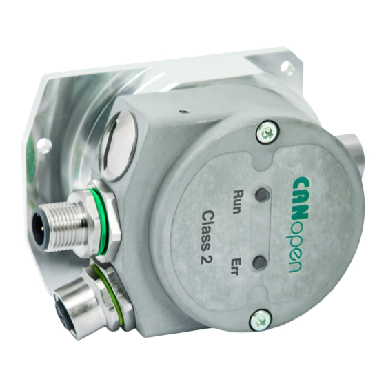
IF55 LIN CB
• SSI to CANopen converter
• Suitable for SSI linear encoders
• Accepts MSB & LSB Aligned protocols up to 30 bits
• Cable and M12 connector outputs
• CANopen in compliance with DS 301 and DS 406 profiles
Suitable for the following models:
IF55 LIN CB
•
IF55 LIN CB-C
•
Lika Electronic
User's guide
•
Tel. +39 0445 806600
DS406 encoder profile
General Contents
1 - Safety summary
2 - Identification
3 - Mechanical installation
4 - Electrical connections
5 - Getting started
6 - CANopen® interface (DS 406)
7 – Setting-up
8 – Default parameters list
•
info@lika.biz
19
21
22
25
34
39
82
85
•
www.lika.biz
Advertisement
Table of Contents

Related Manuals for Lika CANopen IF55 LIN CB


Summary of Contents for Lika CANopen IF55 LIN CB
-
Page 1: User's Guide
IF55 LIN CB-C • 3 - Mechanical installation 4 - Electrical connections 5 - Getting started 6 - CANopen® interface (DS 406) 7 – Setting-up 8 – Default parameters list Lika Electronic • Tel. +39 0445 806600 • info@lika.biz • www.lika.biz... - Page 2 Tous droits réservés. This document and information contained herein are the property of Lika Electronic s.r.l. and shall not be reproduced in whole or in part without prior written approval of Lika Electronic s.r.l. Translation, reproduction and total or partial modification (photostat copies, film and microfilm included and any other means) are forbidden without written authorisation of Lika Electronic s.r.l.
-
Page 3: Table Of Contents
General contents User's guide......................................1 General contents.....................................3 Subject index.....................................6 Typographic and iconographic conventions........................7 Preliminary information................................8 Glossary of CANopen terms..............................9 1 - Safety summary..................................19 1.1 Safety......................................19 1.2 Electrical safety..................................19 1.3 Mechanical safety................................20 2 - Identification..................................21 3 - Mechanical installation..............................22 3.1 Overall dimensions................................22 3.2 Installation on panel (Figure 2).............................23 3.3 Installation with DIN rail clip (Figure 3)........................23 4 - Electrical connections...............................25... - Page 4 6.8 Object dictionary.................................45 6.8.1 Communication Profile Area objects (DS 301)....................47 1000-00 Device type..............................47 1001-00 Error register..............................47 1003 Predefined error field............................47 1005-00 COB-ID SYNC message...........................47 1008-00 Manufacturer Device name.........................47 1009-00 Manufacturer Hardware version......................47 100A-00 Manufacturer Software version.......................47 100C-00 Guard time..............................48 100D-00 Life time factor............................48 1010-01 Store parameters............................48...
- Page 5 Limit switch min...............................73 Limit switch max..............................74 Current operating state............................74 6501-00 Measuring step............................74 6502-00 Number of distinguishable revolutions..................74 6504-00 Supported alarms............................75 6506-00 Supported warnings..........................75 6507-00 Profile and software version......................75 6508-00 Operating time............................75 6509-00 Offset value..............................75 650A-01 Manufacturer offset value........................76 650B-00 Serial number..............................76 6.9 SDO abort codes..................................77 6.10 Emergency (EMCY) objects............................78...
-
Page 6: Subject Index
Subject index 6502-00 Number of distinguishable revolutions .....................74 1000-00 Device type............47 6504-00 Supported alarms.........75 1001-00 Error register...........47 6506-00 Supported warnings........75 1003 Predefined error field.........47 6507-00 Profile and software version....75 1005-00 COB-ID SYNC message.......47 6508-00 Operating time..........75 1008-00 Manufacturer Device name......47 6509-00 Offset value.............75 1009-00 Manufacturer Hardware version....47 650A-01 Manufacturer offset value.......76... -
Page 7: Typographic And Iconographic Conventions
Typographic and iconographic conventions In this guide, to make it easier to understand and read the text the following typographic and iconographic conventions are used: parameters and objects both of the device and the interface are coloured in GREEN; • alarms are coloured in RED;... -
Page 8: Preliminary Information
Preliminary information This guide is designed to describe the technical characteristics, installation and use of the SSI to CANopen gateways of the IF55 series. IF55 series gateways allow the integration of SSI encoders, both rotary and linear, into conventional fieldbuses or industrial Ethernet networks. The present manual is specifically designed to describe the SSI to CANopen IF55 model for linear encoders (order code IF55 LIN CB). -
Page 9: Glossary Of Canopen Terms
Glossary of CANopen terms CANopen, like many other networking systems, has a set of unique terminology. Table below contains a few of the technical terms used in this guide to describe the CANopen interface. They are listed in alphabetical order. The Glossary is owned and copyrighted by the CAN in Automation international users' and manufacturers' group. - Page 10 device recovers from bus off state, it has to transmit the boot- up message and it is recommended to send an Emergency message with the appropriate error code. Controller Area Network (CAN) is a serial bus system originally developed by the Robert Bosch GmbH. It is internationally standardized by ISO 11898-1.
- Page 11 loop controllers supports also multi-channel devices. CiA DS 406 The CANopen device profile for encoders defines the communication of rotating as well as linear sensors. The draft standard proposal for programmable CANopen CiA DSP 302 devices includes CANopen manager functions, dynamic SDO connections, standardized boot-up procedure for NMT Slaves as well as program download.
- Page 12 the interface for feeder sub-systems. CiA DSP 415 The CANopen application profile for asphalt pavers specifies interfaces to different devices used in road construction machinery. CiA DSP 416 The CANopen application profile for building doors specifies interfaces for locks, sensors, and other devices used in electronically controlled building doors.
- Page 13 Conformance test plan Definitions of test cases that have to be passed successfully in order to achieve conformance to a communication standard. The conformance test plan for CAN is standardized by ISO 16845. Conformance test tool A conformance test tool is the implementation of a conformance test plan.
- Page 14 Error control message The CANopen error control messages are mapped to a single 1-byte CAN data frame assigned with a fixed identifier that is derived from the device's Node ID. It is transmitted as boot-up Pre-operational message before entering state after initialization, and it is transmitted if remotely requested by the NMT Master (node guarding) or periodically by the device (heart-beat).
- Page 15 Index 16-bit address to access the CANopen dictionary; for array and records the address is extended by an 8-bit Subindex. Inhibit timer Object in CANopen for PDOs and Emergency messages that forbids for the specified time (inhibit time) a transmission of this communication object.
- Page 16 NMT state machine The NMT state machines support different states and the highest prior CAN message transmitted controls the transition to the states by the NMT Master. Node guarding Mechanism used in CANopen and CAL to detect bus off or disconnected devices.
- Page 17 the corresponding data frame identified by the very same identifier. The remote frame's DLC has the value of the corresponding data frame DLC. The data field of the remote frame has a length of 0 byte. Remote transmission Bit in the arbitration field indicating if the frame is a remote frame (recessive value) or a data frame (dominant value).
- Page 18 sample the inputs mapped into synchronous TPDOs. Receiving this message causes the node to set the outputs to values received in the previous synchronous RPDO. Termination resistor In CAN high-speed networks with bus topology, both ends are terminated with resistors in order to suppress reflections. TIME message Standardized message in CANopen containing the time as a 6- byte value given as ms after midnight and days after 1st...
-
Page 19: Safety Summary
failure to comply with these precautions or with specific warnings elsewhere in this manual violates safety standards of design, manufacture, and intended use of the equipment; Lika Electronic assumes no liability for the customer's failure to comply with these requirements. 1.2 Electrical safety ... -
Page 20: Mechanical Safety
IF55 LIN CANopen® 1.3 Mechanical safety Install the device following strictly the information in the “3 - Mechanical installation” section on page 22; mechanical installation has to be carried out with stationary mechanical parts; do not disassemble the encoder; ... -
Page 21: Identification
Information is listed in the delivery document too. Please always quote the order code and the serial number when reaching Lika Electronic for purchasing spare parts or needing assistance. For any information on the technical characteristics of the product refer to the technical catalogue. -
Page 22: Mechanical Installation
IF55 LIN CANopen® 3 - Mechanical installation WARNING Installation and maintenance operations have to be carried out by qualified personnel only, with power supply disconnected and mechanical parts compulsorily in stop. 3.1 Overall dimensions (values are expressed in mm) Figure 1 MAN IF55 LIN CB E 1.2.odt 3 - Mechanical installation 22 of 88... -
Page 23: Installation On Panel (Figure 2)
IF55 LIN CANopen® 3.2 Installation on panel (Figure 2) Figure 2 The unit is designed for installation on the even surface of a panel. The back flange 2 is fitted with four holes for inserting the fixing screws 1. Tighten the four fixing screws 1 until the unit is properly fastened to the support. - Page 24 IF55 LIN CANopen® Figure 3 Loosen the two screws 6 that fasten the cap 5 to the back flange 2; • open the cap 5 and separate it from the flange 2; please pay attention • to the internal wirings; drill a 4.5 mm diameter hole A in the flange 2;...
-
Page 25: Electrical Connections
IF55 LIN CANopen® 4 - Electrical connections WARNING Power supply must be turned off before performing any electrical connection! Figure 4 4.1 Converter's connection cap (Figure 5) WARNING Do not remove or mount the connection cap with power supply switched ON. Damage may be caused to internal components. -
Page 26: Ssi Connection (Figure 4)
IF55 LIN CANopen® Always replace the connection cap at the end of the operation. Take care in re- connecting the internal connector. Tighten the screws 1 using a tightening torque of approx. 2.5 Nm. WARNING You are required to check that the converter back flange and the connection cap are at the same potential before replacing the connection cap! Figure 5 4.2 SSI connection (Figure 4) -
Page 27: Canopen Converter With Pgs: Cb Version (Figure 4 And Figure 6)
IF55 LIN CANopen® WARNING The max. length of the SSI cable must not exceed 30 m / 98.425 ft. 4.3 CANopen converter with PGs: CB version (Figure 4 and Figure 6) Figure 6 The converter is fitted with two PG9 cable glands for BUS IN and BUS OUT connections. -
Page 28: Canopen Converter With M12 Connectors: Cb-C Version (Figure 4 And Figure 7)
IF55 LIN CANopen® 4.4 CANopen converter with M12 connectors: CB-C version (Figure 4 and Figure 7) The converter is fitted with two M12 5-pin connectors with pin-out in compliance with the CANopen® standard. Therefore you can use standard CANopen cables commercially available. M12 connector A coding (frontal side) -
Page 29: Shield Connection
IF55 LIN CANopen® 4.6 Shield connection Disentangle and shorten the shielding 1 and then bend it over the part 2; finally place the ring nut 3 of the connector. Be sure that the shielding 1 is in tight contact with the ring nut 3. 4.7 POWER SUPPLY DIP switch (Figure 8) WARNING Power supply must be turned off before performing this operation! -
Page 30: Baud Rate: Dip A (Figure 6 And Figure 7)
IF55 LIN CANopen® Figure 8 4.8 Baud rate: DIP A (Figure 6 and Figure 7) WARNING Power supply must be turned off before performing this operation! The transmission rate must be set via hardware by using the DIP A DIP switch. The bit 4 of DIP A must be always set to “ON”. -
Page 31: Node Number: Dip B (Figure 6 And Figure 7)
IF55 LIN CANopen® Available baud rate values: Decimal value Binary value Baud rate 20 Kbit/s 50 Kbit/s 100 Kbit/s 125 Kbit/s 250 Kbit/s 500 Kbit/s (default) 800 Kbit/s 1000 Kbit/s EXAMPLE Set the baud rate to 250Kbit/s: = 100 (binary value, see the table above) Set the baud rate to 500Kbit/s: = 101 (binary value, see the table above) -
Page 32: Rt Bus Termination (Figure 6 And Figure 7)
IF55 LIN CANopen® Switch off the device and set the binary value of the node number considering that: ON = 1, OFF = 0 used EXAMPLE Set the node number = 25: = 0001 1001 (binary value) OFF OFF OFF OFF OFF Set the node number = 55: = 0011 0111 (binary value) -
Page 33: Diagnostic Leds (Figure 4)
IF55 LIN CANopen® 4.11 Diagnostic LEDs (Figure 4) Two LEDs located in the rear side of the converter are designed to show the operating or fault status of the CANopen® interface. GREEN Description Operational The encoder is in state Single flash Stopped The encoder is in state... -
Page 34: Getting Started
IF55 LIN CANopen® 5 - Getting started The following instructions allow the operator to quickly and safely set up the converter in a standard operational mode and to execute its main functions. For complete and detailed information please read the mentioned pages thoroughly. - Page 35 IF55 LIN CANopen® 6005-01 Measuring step setting your application next to the object, see on page 68; 6003-00 now, if you need you can enter the Preset value next to the • Preset value object and then set it in the desired position; see on page (1010-01 Store parameters save the new setting values object;...
- Page 36 IF55 LIN CANopen® If you need a custom resolution: Scaling function control in the 6000-00 Operating parameters object = 1 6005-01 Measuring step setting 2200-05 Physical pulse measure [nm] If you set a 0 preset along the path, when the encoder moves back and cross the 2200-04 Physical Total Resolution [bits] zero, the value immediately after 0 will be 2 - 1, i.e.
-
Page 37: Quick Reference
IF55 LIN CANopen® 8189 8190 8191 5.1 Quick reference After setting the SSI encoder parameters and then using the default settings provided by the manufacturer, you can read immediately the position value. Follow the instructions below to: read the value of the physical measuring step: 6501-00 Measuring step;... - Page 38 IF55 LIN CANopen® Set the Operational mode Master Slave encoder COB-ID Node Read the position every 100 ms Slave encoder Master COB-ID Byte 0 Byte 1 Byte 2 Byte 3 … … High Data bytes as an example To convert the read position value into nanometres [nm] (and into micrometres or millimetres or other engineering unit afterwards) you must multiply the read 6501-00 Measuring step...
-
Page 39: Canopen® Interface (Ds 406)
Lika_IF55__LIN_DS406_Vx.eds, see at www.lika.biz > DISPLAYS & INTERFACES > SIGNAL CONVERTERS & INTERFACES (POSICONTROL). EDS file is available in both English (Lika_IF55__LIN_DS406_Vx_en.eds) and Italian (Lika_IF55__LIN_DS406_Vx_it.eds) versions. Vx is intended to indicate the file version. EDS file has to be installed in the CANopen® Master device. -
Page 40: Initialization State
IF55 LIN CANopen® NMT message: Stop remote node NMT message: Reset node or Reset communication command 6.2.1 Initialization state This is the first state the CANopen® device enters after the power is turned on or after a hardware reset (Reset node command). As soon as the basic CANopen®... -
Page 41: Communication Objects
IF55 LIN CANopen® 6.3 Communication objects Four different kinds of communication messages are used in a CANopen® network: Network management NMT protocol: NMT protocols are used by the Master to manage the nodes and the network, issue the state machine change commands (i.e. -
Page 42: Nmt Objects
IF55 LIN CANopen® 6.4 NMT objects Structure of NMT objects: COB-ID (11 bits) 2 CAN Data Bytes Func.code Node ID Command Slave ID 0000 NMT Func. Slave ID If the Slave ID = 00h, the NMT message is sent to all the nodes in the network. NMT Function: Command NMT Function... -
Page 43: Pdo2 And Pdo3 Sync Mode: Synchronous Transmission
IF55 LIN CANopen® To activate (or deactivate) the cyclic mode it is necessary to set to 0 (or 1) the (1800 TPDO1 parameters, sub 1 most significant bit of COB-ID used by PDO1 object). PDO2 and PDO3 Sync mode: synchronous transmission The transmission of the position value is operated by the Master by sending a SYNC message. -
Page 44: Command
IF55 LIN CANopen® Structure of SDO message: IDENTIFIER from 4 to 8 CAN data bytes COB-ID(hex) F.C. Node-ID Index Data 1 byte MSB 1 byte … … command Index parameter index parameter sub-index Data parameter value 6.7.1 Command The command byte contains the type of telegram transmitted to the CAN network. -
Page 45: Object Dictionary
IF55 LIN CANopen® 6.8 Object dictionary The most important part of a device profile is the Object Dictionary. The Object Dictionary is essentially a grouping of objects accessible via the network in an ordered, pre-defined fashion. The user-related objects are grouped in three main areas: the Communication Profile Area, the Manufacturer Specific Profile Area and the Standardised Device Profile Area. - Page 46 IF55 LIN CANopen® Unsigned/Signed16 data type: Process data bytes byte 4 byte 5 LSByte MSByte Unsigned/Signed32 data type: Process data bytes byte 4 byte 5 byte 6 byte 7 LSByte … … MSByte Unsigned/Signed64 data type: Process data bytes byte 4 byte 5 byte 6 byte 7 byte 8 byte 9 byte 10 byte 11 LSByte …...
-
Page 47: Communication Profile Area Objects (Ds 301)
IF55 LIN CANopen® 6.8.1 Communication Profile Area objects (DS 301) 1000-00 Device type [Unsigned32, ro] It contains information about the device type. The object describes the type of device and its functionality. Default = 0008 0196h = absolute linear encoder, DS 406) 1001-00 Error register [Unsigned8, ro] Should an error occur, the bit 0 in this object will be set to "1". -
Page 48: 100C-00 Guard Time
[Unsigned32, rw] This object allows the operator to restore all parameters to default values (default values are set at the factory by Lika Electronic engineers to allow the operator to run the device for standard operation in a safe mode). -
Page 49: 1014-00 Cob-Id Emcy
IF55 LIN CANopen® Master Slave (Reset node) COB-ID Slave ID Slave Master (Boot-up) COB-ID 700+ID NOTE Save the default values after upload using the store parameters function (see 1010-01 Store parameters object). 1014-00 COB-ID EMCY [Unsigned32, rw] This object defines the COB-ID used to send emergency messages (EMCY). At power on, this object is forced to the default value. - Page 50 IF55 LIN CANopen® RTR allowed on this PDO (not implemented) no RTR allowed on this PDO 11-bit ID (CAN 2.0A) 29-bit ID (CAN 2.0B) if bit 29 = 0 28 … 11 if bit 29 = 1: bits 28-11 of 29-bit-COB-ID bits 10-0 of COB-ID 10 …...
-
Page 51: 1801 Tpdo2 Parameters
IF55 LIN CANopen® NOTE Refer to the “7 – Setting-up” section on page 82 for an example of how the 1800 TPDO1 parameters object is to be set. 1801 TPDO2 parameters PDO2 message is used by default for synchronous transmission of the position value. -
Page 52: 1802 Tpdo3 Parameters
IF55 LIN CANopen® Default = 01h (synchronous transmission at each SYNC command) The position value is transmitted after the set number of SYNC commands. The interval between the SYNC commands must be set next to this 1801 TPDO2 parameters, sub 2 object. WARNING Following an attempt to set the Transmission Type to 0, the value is accepted but the PDO message is not sent;... - Page 53 IF55 LIN CANopen® WARNING It is mandatory to set the bit 30 of COB-ID to 1 (value 0 is not allowed). This means that “No RTR is allowed on the PDO”. At power on, this object is forced to the default value. 02 Transmission type [Unsigned8, rw] ...
-
Page 54: 1A00-01 Tpdo1 Mapping Parameter
IF55 LIN CANopen® - The cyclic transmission or synchronous transmission can be modified by 180xh setting the sub 2 object. If you need the position value to be transmitted every “n” SYNC commands, you must set the “n” value next to the 180xh sub 2 object 01h: synchronous transmission at each SYNC command;... -
Page 55: Manufacturer Specific Profile Area Objects
IF55 LIN CANopen® 6.8.2 Manufacturer Specific Profile Area objects 2104-00 Limit switch min [Unsigned32, rw] This object is used to set the lowest software limit switch (-) in the travel. If the encoder position is greater than the value set in this object, then the bit 6500-00 Operating status 12 of the object is set to “0”. -
Page 56: 2200-02 Ssi Protocol
IF55 LIN CANopen® 2200-02 SSI Protocol [Unsigned8, rw] It sets the protocol used by the SSI encoder to arrange the absolute position information. The SSI protocol can be the 25-bit “LSB Right Aligned” protocol (00h) or the “MSB Left Aligned” protocol (01h). For any information on the SSI protocol please refer to the “User's manual”... -
Page 57: 2200-04 Physical Total Resolution [Bits]
IF55 LIN CANopen® EXAMPLE We need to connect the following linear encoder: SMAX-BG-100. The number of clocks depends on the max. number of information (see the example in the following parameter). Let's say the max. number of information is 6,000, thus it requires 13 clocks. You have to set 0Dh here. For further information refer to the “User's manual”. -
Page 58: 2200-05 Physical Pulse Measure [Nm]
IF55 LIN CANopen® EXAMPLE We need to connect the following linear encoder: SMAX-BG-100. Its resolution is 0.1 mm (see the order code). The max. measuring length of the SMAX linear encoder on the MTAX scale is 600 mm. The max. number of information the encoder can output results from the following calculation: Max. -
Page 59: 2200-06 Bypass
IF55 LIN CANopen® EXAMPLE We need to connect the following linear encoder: SMAX-BG-100. As you can see in the product datasheet, “100” in the order code means a 0.1 mm resolution = 100,000 nm resolution. Thus you have to set the value 0001 86A0h here. -
Page 60: Standardised Device Profile Area Objects (Ds 406)
IF55 LIN CANopen® 6.8.3 Standardised Device Profile Area objects (DS 406) 6000-00 Operating parameters [Unsigned16, rw] Function bit = 0 bit = 1 0 - 1 not used Scaling function control disabled enabled Measuring direction standard inverted 4 … 11 not used Limit switch min. - Page 61 IF55 LIN CANopen® a physical zero setting has been performed in the linear sensor; • 6005-01 Measuring step setting object value is not a multiple of • 2200-05 Physical pulse the physical resolution as set next to the measure [nm] object;...
-
Page 62: Measuring Direction
IF55 LIN CANopen® Measuring direction This is intended to set if the count is increasing (count up information) either when the encoder moves in the standard direction (it is indicated in the encoder's manual) or when the encoder moves in reverse of the standard direction. - Page 63 IF55 LIN CANopen® measuring range 6002-00 Programmable total resolution objects accordingly. 2200-06 Bypass Furthermore, if the object (see on page 59) is set to “1” = enabled, the scaling function -even if enabled- is ignored and the position information is outputted as it is. If the Scaling function control is disabled (the bit 2 in the 6000-00 Operating parameters...
- Page 64 IF55 LIN CANopen® If you set a preset along the path, when the encoder moves back and cross the 2200-04 Physical Total Resolution [bits] zero, the value immediately after 0 will be 2 - 1, i.e. 131,071. 131069 131070 131071 EXAMPLE We need to connect the following linear encoder: SMAX-BG-100.
-
Page 65: 6002-00 Programmable Total Resolution
IF55 LIN CANopen® 6005-01 Measuring step setting object value is not a multiple of • 2200-05 Physical pulse the physical resolution as set next to the measure [nm] object; (6001-00 Total measuring range 6002-00 the measuring range • Programmable total resolution objects) is not a power of 2 submultiple of the maximum measuring range. -
Page 66: 6003-00 Preset Value
IF55 LIN CANopen® 2200-06 Bypass Furthermore, if the object (see on page 59) is set to “1” = enabled, the scaling function -even if enabled- is ignored and the position information is outputted as it is. 6001-00 Total measuring range This object is exactly the same as the object. - Page 67 IF55 LIN CANopen® We will obtain the following information sequence: Transmitted value = read position (=”1000”) + 6003-00 Preset value 6509-00 Offset value (=”50”) - (=”1000”) = 50. The following transmitted value will be: Transmitted value = read position (=”1001”) + 6003-00 Preset value 6509-00 Offset value (=”50”) -...
-
Page 68: 6004-00 Position Value
IF55 LIN CANopen® 6004-00 Position value [Unsigned32, ro] This object contains the current position value of the encoder. The output value is scaled according to the scaling parameters (if the scaling function is enabled), see the bit 2 Scaling function control of the 6000-00 Operating parameters object. - Page 69 IF55 LIN CANopen® 6005-01 Measuring step setting automatically sets the default value of the 6501-00 Measuring step objects accordingly. Furthermore, if the 2200-06 Bypass object (see on page 59) is set to “1” = enabled, the scaling function -even if enabled- is ignored and the position information is outputted as it is.
- Page 70 IF55 LIN CANopen® WARNING When you enable the scaling function (Scaling function control = 1), a counting error, i.e. a jump in the position count, may occur if the following conditions arise: a physical zero setting has been performed in the linear sensor; •...
- Page 71 IF55 LIN CANopen® Thus, in a default configuration the number of information is: Max. measuring length Total Physical Resolution = = 6000 Resolution Let's assume that you need 2000 information to be provided to output for the max. measuring length. It follows that you need to calculate and then set a custom resolution.
-
Page 72: 6008-00 High Precision Position Value
IF55 LIN CANopen® NOTE Refer to the “7 – Setting-up” section on page 82 for an example of setting the 6005-01 Measuring step setting object. 6008-00 High precision position value [Unsigned64, ro] 6004-00 Position value This object is the same as the object, yet it is 64-bit long. -
Page 73: 6500-00 Operating Status
IF55 LIN CANopen® 6500-00 Operating status [Unsigned16, ro] Function bit = 0 bit = 1 0 - 1 not used Scaling Disabled Enabled Measuring direction Standard Inverted 4 … 11 not used position > position < 2104-00 2104-00 Limit switch min Limit switch Limit switch position <... -
Page 74: Limit Switch Max
IF55 LIN CANopen® To enable this function set the bit 12 Limit switch min. in the 6000-00 Operating parameters object to "1". Limit switch max 2105-00 Limit switch If the encoder position is less than the value set in the object, the bit 13 of this object is set to “0”. -
Page 75: 6504-00 Supported Alarms
IF55 LIN CANopen® 6504-00 Supported alarms [Unsigned16, ro] This object contains the information on the alarms supported by the encoder. No alarms are supported in this encoder. Default = 0000h (no alarms supported) 6506-00 Supported warnings [Unsigned16, ro] This object contains the information on the warnings supported by the encoder. No warnings are supported in this encoder. -
Page 76: 650A-01 Manufacturer Offset Value
IF55 LIN CANopen® 650A-01 Manufacturer offset value [Integer32, ro] This object contains the manufacturer-specific offset value. This is the difference between the physical zero position of the encoder (zero set mechanically) and the zero position set by the manufacturer (zero set via software). -
Page 77: Sdo Abort Codes
IF55 LIN CANopen® 6.9 SDO abort codes Here follows the list and meaning of the SDO abort codes indicated by CANopen but not necessarily supported by the manufacturer. For complete information please refer to the “SDO abort transfer protocol” section in the “CiA Draft Standard 301”... -
Page 78: Emergency (Emcy) Objects
IF55 LIN CANopen® 0800 0024h No data available 6.10 Emergency (EMCY) objects Emergency objects (EMCY) are triggered by the device when an internal error occurs. EMCY structure: IDENTIFIER CAN Data Byte COB-ID(hex) 3 … 7 1014-00 see the Sub of error Error code Specific code COB-ID EMCY... -
Page 79: Node Guarding Protocol
IF55 LIN CANopen® 8110h CAN overrun (objects lost) 8120h CAN in error passive mode 8130h Life guard error or heartbeat error 8140h Recovered from bus off 8150h CAN-ID collision 8200h Protocol error - generic 8210h PDO not processed due to length error 8220h PDO length exceeded 8230h... - Page 80 IF55 LIN CANopen® after the Node Guarding protocol becomes active is 0. The Toggle bit in the Node Guarding protocol is only reset to 0 when reset_communication is passed (no other change of the state resets the Toggle bit). If a response is received with the same value of the Toggle bit as in the preceding response then the new response is handled as if it was not received.
- Page 81 IF55 LIN CANopen® Node life time = 100C-00 Guard time 100D-00 Life time factor “Node guarding” is enabled if Node life time 0. If the Slave does not receive an RTR message before the Node life time has 1001-00 expired, it warns activating a “Life Guarding Event”.
-
Page 82: Setting-Up
IF55 LIN CANopen® 7 – Setting-up Here following are some examples of transmission between Master and Slave devices. A generic “ID” value is used to indicate the unit address; the address of the Master is always 0. All values are expressed in hexadecimal notation. 7.1 Setting the Operational, Pre-operational state... -
Page 83: Setting The Preset Value
IF55 LIN CANopen® Slave Master (Set confirmation) COB.ID Index Process data 580+ID 7.5 Setting the Preset value 6003-00 Preset value (preset = 1000 = 03E8h) Master Slave (Set request) COB.ID Index Process data 600+ID Slave Master (Set confirmation) COB.ID Index Process data... -
Page 84: Enabling The Cyclic Mode
IF55 LIN CANopen® Slave Master (Set confirmation) COB.ID Index Process data 580+ID 7.8 Enabling the Cyclic mode 6200-00 Cyclic timer Set the cyclic time (100 ms = 64h) Master Slave (Set request) COB.ID Index Process data 600+ID Slave Master (Set confirmation) COB.ID Index Process data... -
Page 85: Default Parameters List
IF55 LIN CANopen® 8 – Default parameters list Default values are expressed in hexadecimal notation. Parameters list Default value 1000-00 Device type 0008 0196 1001-00 Error register 1003 Predefined error field 1005-00 COB-ID SYNC message 0000 0080 1008-00 Manufacturer Device IF55LIN_CB* name 1009-00 Manufacturer... - Page 86 IF55 LIN CANopen® 6500-00 Operating status 0000 6504-00 Supported alarms 0000 6506-00 Supported warnings 0000 6507-00 Profile and software 0301 0101 version 6508-00 Operating time FFFF FFFF 6509-00 Offset value 0000 0000 650A-01 Manufacturer offset 0000 0000 value, sub 1 650B-00 Serial number FFFF FFFF * Text value...
- Page 87 This page intentionally left blank...
- Page 88 03.10.2019 range updated in some parameters, new POWER SUPPLY DIP switch 04.07.2022 “4.2 SSI connection (Figure 4)“ section updated Lika Electronic Via S. Lorenzo, 25 • 36010 Carrè (VI) • Italy Tel. +39 0445 806600 Fax +39 0445 806699 info@lika.biz...
Need help?
Do you have a question about the CANopen IF55 LIN CB and is the answer not in the manual?
Questions and answers