Advertisement
Quick Links
Smart encoders & actuators
LD360
LD365
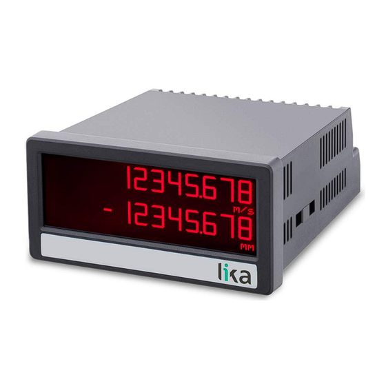
• Multifunction touch-screen display for incremental encoders
• Tachometer, pulse counter, position indicator
• Position and speed values available simultaneously on display
• Input frequencies up to 1MHz
• Digital, analogue, serial, and relay outputs
• DC / AC power supply: 18÷30Vdc or 115÷230Vac
Suitable for the following models:
LD360-P8-...
•
LD365-P8-...
•
LD360-PM-...
•
LD365-PM-...
•
Lika Electronic
User's guide
•
Tel. +39 0445 806600
General Contents
Preliminary information
1 - Safety summary
2 - Identification
3 - Mounting instructions
4 - Electrical connections
5 - Display and touch screen
6 – Menus and parameters
7 - Appendix
8 - Modbus RTU Interface
9 - Parameters / serial codes
•
info@lika.biz
11
13
15
16
18
28
32
105
106
110
•
www.lika.biz
Advertisement

Related Manuals for Lika LD360


Summary of Contents for Lika LD360
- Page 1 User's guide Smart encoders & actuators LD360 LD365 • Multifunction touch-screen display for incremental encoders • Tachometer, pulse counter, position indicator • Position and speed values available simultaneously on display • Input frequencies up to 1MHz • Digital, analogue, serial, and relay outputs •...
- Page 2 Tous droits réservés. This document and information contained herein are the property of Lika Electronic s.r.l. and shall not be reproduced in whole or in part without prior written approval of Lika Electronic s.r.l. Translation, reproduction and total or partial modification (photostat copies, film and microfilm included and any other means) are forbidden without written authorisation of Lika Electronic s.r.l.
- Page 3 4.1 DC power supply..................................19 4.2 AC power supply (-PM- order code)...........................19 4.3 Auxiliary voltage output..............................20 4.4 A, B incremental inputs (LD360 model)........................21 4.4.1 Wiring of the incremental inputs........................21 4.4.2 Note about mechanical switching contacts....................21 4.5 A, /A, B, /B incremental inputs (LD365 model).......................22 4.5.1 Wiring of the incremental inputs........................22...
- Page 4 Linearization mode................................39 preselection................................40 parameter...................................40 Back up memory................................40 Factory settings................................40 6.3 Speed A Settings menu..............................41 Display value SA................................41 Base frequency (Hz) SA...............................41 Programming Display value SA and Base frequency (Hz) SA parameters.............41 Decimal point SA................................43 Sampling time (s) SA..............................43 Wait time (s) SA................................43 Standstill time (s) SA..............................44...
- Page 5 Source....................................69 Factor.....................................70 Divider....................................70 Additive value...................................70 6.9 Preselection values menu..............................71 Preselection 1..................................71 Preselection 2..................................71 Preselection 3..................................71 Preselection 4..................................71 6.10 Preselection 1 menu................................72 Source 1....................................72 Mode 1....................................73 Hysteresis 1..................................75 Pulse time 1 (s)................................76 Output target 1................................76 Output polarity 1................................76 Output lock 1..................................76 Start up delay 1 (s)................................77 Event color...
- Page 6 6.14 Serial menu..................................84 Unit number..................................84 Serial baud rate................................84 Serial format..................................84 Serial init.....................................85 Serial protocol..................................85 Serial timer (s)..................................86 Serial value..................................86 MODBUS....................................86 6.15 Analog menu..................................87 Analog source...................................87 Analog format..................................88 Analog start..................................88 Analog end..................................88 Analog gain (%)................................89 Analog offset..................................89 6.16 Command menu................................90 Input 1 action...................................90 Input 1 config...................................92...
- Page 7 8.2.2 Access to parameters..............................108 8.2.3 Access to current data............................108 8.2.4 Access to status registers............................108 8.2.5 Read Coils and Write Single Coil........................108 8.2.6 Diagnostics..................................109 9 - Parameters / serial codes.............................110 9.1 General menu..................................110 9.2 Speed A Settings menu..............................110 9.3 Speed B Settings menu..............................111 9.4 Counter A Settings menu..............................111 9.5 Counter B Settings menu..............................112 9.6 Collection Settings menu..............................112...
- Page 8 Display value SA...............41 Output polarity 3.............81 Display value SB...............47 Output polarity 4.............83 Divider...................70 Output target 1..............76 Output target 2..............78 Output target 3..............80 Encoder properties LD360..........38 Output target 4..............82 Encoder properties LD365..........39 Encoder supply..............39 Event color 1..............77 P1(X)..................102 Event color 2..............79 P1(Y)..................102 Event color 3..............81...
- Page 9 Pulse time 4 (s)..............82 Serial timer (s)..............86 Serial value................86 Set value CA...............53 Quickstart key..............100 Set value CB...............59 Source.................69, 101 Sampling time (s) SA............43 Source 1................72 Sampling time (s) SB............49 Source 2................78 Scale units CA..............54 Source 3................80 Scale units CB..............60 Source 4................82 Scale units counter............67 Source dual down............97 Scale units frequency.............65...
-
Page 10: Typographic And Iconographic Conventions
Typographic and iconographic conventions In this guide, to make it easier to understand and read the text the following typographic and iconographic conventions are used: parameters and objects both of the device and the interface are coloured in GREEN; • alarms are coloured in RED;... -
Page 11: Preliminary Information
LD360-...-AVI / LD365-...-AVI provides additional 16-bit analogue output, four control outputs • and RS-232 / RS-485 serial interface; LD360-...-DO / LD365-...-DO further offers four control outputs and RS-232 / RS-485 serial • interface; LD360-...-RO / LD365-...-RO is equipped with two relay outputs. - Page 12 Operational modes All functions can be configured in the parameter menu. The device can be set to one of the following operation modes: Operation as frequency display for incremental input signals, see the “6.3 Speed A Settings • menu” section on page 41 and the “6.4 Speed B Settings menu” section on page 47. ◦...
-
Page 13: Safety Summary
• failure to comply with these precautions or with specific warnings elsewhere in this manual violates safety standards of design, manufacture, and intended use of the equipment; • Lika Electronic assumes no liability for the customer's failure to comply with these requirements. 1.2 Electrical safety •... - Page 14 LD360 • LD365 • delicate electronic equipment: handle with care; • do not subject the device to knocks or shocks; • respect the environmental characteristics of the device. MAN LD360_LD365 E 1.0.odt 1 - Safety summary 14 of 120...
- Page 15 Information is listed in the delivery document too. Please always quote the order code and the serial number when reaching Lika Electronic for purchasing spare parts or needing assistance. For any information on the technical characteristics of the product, refer to the technical catalogue.
-
Page 16: Mounting Instructions
LD360 • LD365 3 - Mounting instructions WARNING Installation and maintenance operations have to be carried out by qualified personnel only, with power supply disconnected and mechanical parts compulsorily in stop. 3.1 Overall dimensions Mount the display into the provided cut-out (w x h approx. 91 x 43 mm, 3.58” x 1.69’’) without panel clips. - Page 17 LD360 • LD365 3.2 Installation The device is allowed to be installed and operated only within the permissible temperature range (-20°C +60°C / -4°F +140°F). Please ensure an adequate ventilation and avoid any direct contact between the device and gases / liquids.
-
Page 18: Electrical Connections
LD360 • LD365 4 - Electrical connections WARNING Power supply must be turned off before performing any electrical connection! The terminal block screws must be tightened using a slotted screwdriver having a 2 mm wide blade. LD360 terminal scheme LD365 terminal scheme MAN LD360_LD365 E 1.0.odt... - Page 19 LD360 • LD365 4.1 DC power supply DC power supply technical specifications (-P8- order code) Input voltage: 18Vdc ... 30Vdc Protection circuit: reverse polarity protection Power consumption: approx. 100 mA (unloaded) Fuse protection: external fuse T 0.5 A The unit accepts DC supply from 18 to 30 V through terminal blocks 1 and 2.
- Page 20 LD360 • LD365 4.3 Auxiliary voltage output Auxiliary voltage output technical specifications (LD360 model) DC version: 24Vdc (approx. 1 V lower than the main power supply voltage), max. 250 mA AC version: 24Vdc (±15%), max. 150 mA up to 45°C / 80 mA when more than 45°C...
- Page 21 LD360 • LD365 4.4 A, B incremental inputs (LD360 model) A, B incremental inputs technical specifications Number inputs (channels): 2 (A, B) Configuration: PNP, NPN, Namur, Tri-State Format: HTL (Low = 0 … 3 V, High = 9 … 30 V) Frequency: max.
- Page 22 LD360 • LD365 4.5 A, /A, B, /B incremental inputs (LD365 model) AB, /AB incremental inputs technical specifications Number inputs (channels): 2 with inverted signals (A, /A, B, /B) Configuration: RS-422, HTL differential, HTL PNP, HTL NPN RS-422: max. 1 MHz (RS-422 differential signal > 0.5 V HTL differential: max.
- Page 23 LD360 • LD365 4.6 Control inputs Control inputs technical specifications Number of inputs: Format: HTL, PNP (Low = 0 … 3 V, High = 9 … 30 V) Frequency: max. 10 kHz Load: max. 2 mA / Ri > 15 kOhm / 470 pF The three control inputs at terminal blocks 10, 11, and 12 have HTL PNP characteristics.
- Page 24 LD360 • LD365 4.7 Analogue output (-AVI- order code) Analogue output technical specifications Configuration: Current or voltage operation Voltage output (0): -10 V … +10 V (max. 2 mA) Current output (1): 0 … 20 mA (burden: max. 270 Ohm) Current output (2): 4 …...
- Page 25 LD360 • LD365 4.8 Serial interface (-AVI- and -DO- order codes) Serial interface technical specifications Format: RS-232 (-AVI1- and -DO1-) or RS-485 (-AVI2- and -DO2-) Baud rate: 9600, 19200 and 38400 baud A serial interface (RS-232 / RS-485) is available through terminal blocks 16, 17, and 18.
- Page 26 LD360 • LD365 4.9 Control outputs (-AVI- and -DO- order codes) Control outputs technical specifications Number of outputs: Format / level: 5 … 30 V (depending on the voltage level provided to terminal block 19 - COM+), PNP Output current: max.
- Page 27 LD360 • LD365 4.10 Relay outputs (-RO order code) Relay outputs technical specifications Number of outputs: Configuration: potential-free changeovers AC switching capacity: max. 250 Vac / 3 A / 750 VA DC switching capacity: max. 150 Vdc / 2 A / 50 W Reaction time: <...
-
Page 28: Display And Touch Screen
LD360 • LD365 5 - Display and touch screen 5.1 Screen structure for parametrization Menus and parameters are described in the “6 – Menus and parameters” section on page 32. Start setup procedure To enter the menus and edit the parameters, keep the touchscreen pressed for 3 seconds. - Page 29 LD360 • LD365 5.2 Screen structure during operation The following screens are available during operation. Depending on the device version and the selected operation mode, not all displays will be shown. Refer Start display also to the parameter on page 94.
- Page 30 LD360 • LD365 Display for quick start of the preselection values setting process (see the “ 6.9 Preselection values menu “ section on page 71 ) The desired command key (“EDIT PRESEL.” or “SHOW PRESEL.”) can be chosen by setting the Quickstart parameter in the “6.17 Display...
- Page 31 LD360 • LD365 5.3 Error messages If a measurement result, which is shown on the display, is outside the allowed display range, an error message is briefly displayed every 2 seconds. The message explains the value that is out-of-range. NOTE The error messages are reset automatically as soon as the corresponding display value is within the allowed range.
- Page 32 General menu, see the “6.2 General menu” section on page 38 Operational mode, see on page 38 Encoder properties LD360, see on page 38 (LD360 model) Encoder properties LD365, see on page 39 (LD365 model) Encoder supply, see on page 39...
- Page 33 LD360 • LD365 Operational mode This menu is displayed only if the parameter in the “6.2 General menu” section on page 38 is set to one of the following options: 2 = SUM A+B, 3 = DIF A-B, 4 = RATIO B/A, 5 = % DEVIA B/A.
- Page 34 LD360 • LD365 Second decimal point CB, see on page 62 Second scale units CB, see on page 63 Operational mode This menu is displayed only if the parameter in the “6.2 General menu” section on page 38 is set to one of the following options: 2 = SUM A+B, 3 = DIF A-B, 4 = RATIO B/A, 5 = % DEVIA B/A.
- Page 35 LD360 • LD365 Output polarity 1, see on page 76 Output lock 1, see on page 76 Start up delay 1 (s), see on page 77 Event color 1, see on page 77 It is only available for devices with order codes AVI, DO, or RO.
- Page 36 LD360 • LD365 Pulse time 4 (s), see on page 82 Output target 4, see on page 82 Output polarity 4, see on page 83 Output lock 4, see on page 83 Start up delay 4 (s), see on page 83...
- Page 37 LD360 • LD365 Display menu, see the “6.17 Display menu” section on page 94 Start display, see on page 94 Source single, see on page 95 Source dual top, see on page 96 Source dual down, see on page 97...
- Page 38 8 A/B 90 x4 (fourfold edge evaluation x4). Encoder properties LD360 This parameter is only available for LD360 model. It allows to set the characteristics of the pulse inputs for LD360. 0 PNP PNP (switch to +) 1 NPN NPN (switch to -) Connect sensor (–) to GND and sensor (+) to input...
- Page 39 LD360 • LD365 Encoder properties LD365 This parameter is only available for LD365 model. It allows to set the characteristics of the pulse inputs for LD365. 0 RS422 RS-422 standard 1 HTL DIFFERENTIAL HTL differential 2 HTL PNP HTL PNP single ended (switch to +)
- Page 40 LD360 • LD365 Pin preselection This parameter allows to set the PIN code to lock the quick start of the Preselection values menu used to enter the preselection values, see the “5.2 Screen structure during operation” section on page 29. Refer also to the “6.9 Preselection values menu”...
- Page 41 LD360 • LD365 6.3 Speed A Settings menu The Speed A Settings menu allows to set the parameters for channel A operation as tachometer or frequency meter. Operational mode Depending on the operation mode selected (see the parameter in the “6.2 General menu” section on page 38), only input A is active or both input A and input B with 90°...
- Page 42 LD360 • LD365 N: number of increments (pulses) per turn (for instance 1024, if the connected encoder has 1024 PPR resolution). EXAMPLE 1 You need the SPEED A operation mode and want to display the values expressed in RPM. Let's say the number of increments per turn of the encoder is 1024.
- Page 43 LD360 • LD365 Decimal point SA It sets the position of the decimal point. 0 NO No decimal point 1 0000000.0 Decimal point placed in the specified position 2 000000.00 Decimal point placed in the specified position 3 00000.000 Decimal point placed in the specified position 4 0000.0000...
- Page 44 LD360 • LD365 Standstill time (s) SA This parameter sets the time after which a standstill condition is acknowledged. When the “frequency = 0 Hz” condition is detected, after the delay set next to this parameter the unit warns of the standstill condition and reactivates the Start up delay x (s) parameter in the Preselection 1 …...
- Page 45 LD360 • LD365 Sampling time (s) Exponential filter, T (63 %) = 8x 8 cycle filter Sampling time Exponential filter, T (63 %) = 16x 16 cycle filter (s) SA Scale units SA This parameter sets the required engineering unit. It does not affect the...
- Page 46 LD360 • LD365 25 ml/min 26 gr/min 27 inch/min 28 H:M A customized measuring unit with up to 16 digits can be edited using this parameter. key the Edit Unit menu When you press the appears. A measuring unit can be created using the arrow keys (by pressing and holding the arrow key down the characters scroll fast).
- Page 47 LD360 • LD365 6.4 Speed B Settings menu The Speed B Settings menu allows to set the parameters for channel B operation as tachometer or frequency meter. Operational mode This menu is displayed only if the parameter in the “6.2 General menu”...
- Page 48 LD360 • LD365 N: number of increments (pulses) per turn (for instance 1024, if the connected encoder has 1024 PPR resolution). EXAMPLE 1 You need the SPEED B operation mode and want to display the values expressed in RPM. Let's say the number of increments per turn of the encoder is 1024.
- Page 49 LD360 • LD365 Decimal point SB It sets the position of the decimal point. 0 NO No decimal point 1 0000000.0 Decimal point placed in the specified position 2 000000.00 Decimal point placed in the specified position 3 00000.000 Decimal point placed in the specified position 4 0000.0000...
- Page 50 LD360 • LD365 Standstill time (s) SB This parameter sets the time after which a standstill condition is acknowledged. When the “frequency = 0 Hz” condition is detected, after the delay set next to this parameter the unit warns of the standstill condition and reactivates the Start up delay x (s) parameter in the Preselection 1 …...
- Page 51 LD360 • LD365 Sampling time (s) Exponential filter, T (63 %) = 8x 8 cycle filter Sampling time Exponential filter, T (63 %) = 16x 16 cycle filter (s) SB Scale units SB This parameter sets the required engineering unit. It does not affect the...
- Page 52 LD360 • LD365 25 ml/min 26 gr/min 27 inch/min 28 H:M A customized measuring unit with up to 16 digits can be edited using this parameter. key the Edit Unit menu When you press the appears. A measuring unit can be created using the arrow keys (by pressing and holding the arrow key down the characters scroll fast).
- Page 53 LD360 • LD365 6.5 Counter A Settings menu The Counter A Settings menu allows to set the parameters for channel A operation as pulse counter or position indicator. Factor CA It sets the scaling factor for channel A. EXAMPLE Factor CA parameter is set to 1.23456, 100,000 input pulses will result in a...
- Page 54 LD360 • LD365 Scale units CA This parameter sets the required engineering unit for the main counter A. It does not affect the calculation of the display value, it is just a label to be shown next to the display value. The number of decimal places must be set in the Decimal point CA parameter, see on page 53.
- Page 55 LD360 • LD365 When you press the key the Edit Unit menu appears. A measuring unit can be created using the arrow keys (by pressing and holding the arrow key down the characters scroll fast). key to save the Edit Unit menu.
-
Page 56: Total Counter
LD360 • LD365 0 OFF No batch counter & no total counter INCREMENT Batch counter operates by incrementing BATCH DECREMENT Batch counter operates by decrementing BATCH The batch counter is operated only via external 3 USE INPUTS ONLY commands (see the Command menu, refer to the “6.16 Command menu”... - Page 57 LD360 • LD365 Second scale units CA This parameter sets the required engineering unit for the second counter A. It does not affect the calculation of the display value, it is just a label to be shown next to the display value. The number of decimal places must be set in the Second decimal point CA parameter, see on page 56.
- Page 58 LD360 • LD365 can be edited using this parameter. key the Edit Unit menu When you press the appears. A measuring unit can be created using the arrow keys (by pressing and holding the arrow key down the characters scroll fast).
- Page 59 LD360 • LD365 6.6 Counter B Settings menu The Counter B Settings menu allows to set the parameters for channel B operation as pulse counter or position indicator. Operational mode This menu is displayed only if the parameter in the “6.2 General menu”...
- Page 60 LD360 • LD365 Scale units CB This parameter sets the required engineering unit for the main counter B. It does not affect the calculation of the display value, it is just a label to be shown next to the display value. The number of decimal places must be set in the Decimal point CB parameter, see on page 59.
- Page 61 LD360 • LD365 When you press the key the Edit Unit menu appears. A measuring unit can be created using the arrow keys (by pressing and holding the arrow key down the characters scroll fast). key to save the Edit Unit menu.
- Page 62 LD360 • LD365 0 OFF No batch counter & no total counter INCREMENT Batch counter operates by incrementing BATCH DECREMENT Batch counter operates by decrementing BATCH The batch counter is operated only via external 3 USE INPUTS ONLY commands (see the Command menu, refer to the “6.16 Command menu”...
- Page 63 LD360 • LD365 Second scale units CB This parameter sets the required engineering unit for the second counter B. It does not affect the calculation of the display value, it is just a label to be shown next to the display value. The number of decimal places must be set in the Second decimal point CB parameter, see on page 62.
- Page 64 LD360 • LD365 can be edited using this parameter. key the Edit Unit menu When you press the appears. A measuring unit can be created using the arrow keys (by pressing and holding the arrow key down the characters scroll fast).
- Page 65 LD360 • LD365 6.7 Collection Settings menu This menu allows to set the decimal point as well as the corresponding engineering unit for the linked results (“Frequency collection” and “Counter collection”). Operational mode This menu is displayed only if the parameter in the “6.2...
- Page 66 LD360 • LD365 13 m 14 inch 15 feet 16 Stueck 17 pcs 18 sec 19 min 20 Min:Sec 21 H:M:S 22 Min:Sec:00 23 l/min 24 gal/min 25 ml/min 26 gr/min 27 inch/min 28 H:M A customized measuring unit with up to 16 digits can be edited using this parameter.
- Page 67 LD360 • LD365 Decimal point counter This parameter sets the position of the decimal point for the counter linked result. 0 NO No decimal point 1 0000000.0 Decimal point placed in the specified position 2 000000.00 Decimal point placed in the specified position 3 00000.000...
- Page 68 LD360 • LD365 18 sec 19 min 20 Min:Sec 21 H:M:S 22 Min:Sec:00 23 l/min 24 gal/min 25 ml/min 26 gr/min 27 inch/min 28 H:M A customized measuring unit with up to 16 digits can be edited using this parameter.
- Page 69 LD360 • LD365 6.8 Scaling settings menu The Scaling settings menu allows to set additional scaling factors by means of which the desired process value can be calculated further. The scaled result value is stored and available in the 8 – SCALED RESULT of the SOURCE parameters.
- Page 70 LD360 • LD365 The reference source is the value resulting from the combination of both counters of channel A and channel B (A+B, A-B, B/A, …). This option is Operational mode available only if 7 COUNTER COLL. parameter in the “6.2 General menu” section on...
- Page 71 LD360 • LD365 6.9 Preselection values menu The Preselection values menu is used to set the preselection values or the switching points. The preselection values / switching points are always referred to the selected SOURCE of the “Preselection” menu. This menu is only available for devices with order codes AVI, DO or RO.
- Page 72 LD360 • LD365 6.10 Preselection 1 menu The Preselection 1 menu is only available for devices with order codes AVI, DO and RO. It allows to set the reference source, the switch conditions and further Preselection characteristics of Source 1 Preselection 1.
- Page 73 LD360 • LD365 menu” section on page 38 is set to one of the following options: 2 = SUM A+B, 3 = DIF A-B, 4 = RATIO B/A, 5 = % DEVIA B/A. The reference source is the value resulting from 8 SCALED RESULT the additionally scaled process value, see the “6.8...
- Page 74 LD360 • LD365 Preselection Display value is less than or equal to 1, e.g. an underspeed is detected (start up delay Start up delay 1 (s) setting -see the parameter on page 77- is advisable). 4 RESULT <= PRES Hysteresis 1...
- Page 75 LD360 • LD365 INCREMENT BATCH or 2 = DECREMENT BATCH so activating the batch mode, the corresponding batch counter increments or decrements when the display value is set to Preselection 1 and when the (Source 1 = “1 = corresponding reference source COUNTER A”...
- Page 76 LD360 • LD365 Pulse time 1 (s) Preselection 1 Duration of the output pulse for the switching condition of value. 0.000 No output pulse (static signal) … 60.000 Pulse duration = 60 seconds Output target 1 Preselection 1 Assignment of an output or relay for the switching condition of value.
- Page 77 LD360 • LD365 Start up delay 1 (s) Preselection Start up delay setting for the switching condition of This adjustment only applies to the switching conditions 1 - |RESULT|<=| PRES| and 4 - RESULT<=PRES (see the Mode 1 parameter on page 73) and for...
- Page 78 LD360 • LD365 6.11 Preselection 2 menu The Preselection 2 menu is only available for devices with order codes AVI, DO and RO. It allows to set the reference source, the switch conditions and further Preselection characteristics of Source 2 Preselection 2.
- Page 79 LD360 • LD365 Output polarity 2 Preselection 2. For complete Polarity for the switching condition of Output polarity 1 information please refer to the parameter in the “6.10 Preselection 1 menu” section on page 72. Output lock 2 Preselection 2. For complete information...
- Page 80 LD360 • LD365 6.12 Preselection 3 menu The Preselection 3 menu is only available for devices with order codes AVI, DO and RO. It allows to set the reference source, the switch conditions and further Preselection characteristics of Source 3 Preselection 3.
- Page 81 LD360 • LD365 Output polarity 3 Preselection 3. For complete Polarity for the switching condition of Output polarity 1 information please refer to the parameter in the “6.10 Preselection 1 menu” section on page 72. Output lock 3 Preselection 3. For complete information...
- Page 82 LD360 • LD365 6.13 Preselection 4 menu The Preselection 4 menu is only available for devices with order codes AVI, DO and RO. It allows to set the reference source, the switch conditions and further Preselection characteristics of Source 4 Preselection 4.
- Page 83 LD360 • LD365 Output polarity 4 Preselection 4. For complete Polarity for the switching condition of Output polarity 1 information please refer to the parameter in the “6.10 Preselection 1 menu” section on page 72. Output lock 4 Preselection 4. For complete information...
- Page 84 LD360 • LD365 6.14 Serial menu The Serial menu allows to configure the basic settings of the serial interface (terminal blocks 16, 17 and 18). For complete information on the serial port features, please refer to the “4.8 Serial interface (-AVI- and -DO- order codes)”...
- Page 85 LD360 • LD365 Serial init This parameter allows to set the baud rate for the transmission of the initialization values to the OS software tool. If you set transmission values higher than 9,600 baud, the duration of the initialization procedure will be shortened.
- Page 86 LD360 • LD365 Serial timer (s) This parameter sets the cycle time for the cyclic transmission of data set in the Serial value parameter when using the serial output. The value is expressed in seconds. In case of a serial request, the cyclic transmission is stopped for 20 s.
- Page 87 LD360 • LD365 6.15 Analog menu The Analog menu allows to configure the basic settings of the analogue output (terminal blocks 13 and 14 / 15). For complete information on the analogue output features, please refer to the “4.7 Analogue output (-AVI- order code)” section on page 24.
- Page 88 LD360 • LD365 Operational mode parameter in the “6.2 General menu” section on page 38 is set to one of the following options: 2 = SUM A+B, 3 = DIF A-B, 4 = RATIO B/A, 5 = % DEVIA B/A.
- Page 89 LD360 • LD365 Analog gain (%) This parameter sets the maximum conversion of the analogue output expressed in percentage (%). 000.00 Smallest gain 100.00 Default value 110.00 Highest gain EXAMPLE If you set “102.00” next to this item the result will be a conversion of 10.2 V or Analog end 20.4 mA when the value set next to the...
-
Page 90: Reset Min/Max
LD360 • LD365 6.16 Command menu The Command menu allows to configure the operation of the inputs “10 - Ctrl. In 1”, “11 - Ctrl. In 2” and “12 - Ctrl. In 3”. For complete information on the control inputs features, please refer to the “4.6 Control inputs”... - Page 91 LD360 • LD365 START PRESELECT N.A. ACTIVATE DATA N.A. STORE DATA N.A. TESTPROGRAM N.A. SET RED COLOR The display lights up red. The colour can be changed by setting an event- dependent switching condition (see the Event color Event color...
- Page 92 LD360 • LD365 Settings menu” section on page 53). INC. BATCH B It increases the batch counter of channel B (see the “6.6 Counter B Settings menu” section on page 59). DEC. BATCH B It decreases the batch counter of channel B (see the “6.6 Counter B...
- Page 93 LD360 • LD365 Input 2 config. This parameter sets the switching characteristics of the input “11 - Ctrl. In 2”. Input 1 config. For complete information please refer to the parameter on page 92. Input 3 action This parameter sets the function of the input “12 - Ctrl. In 3”. For complete...
- Page 94 LD360 • LD365 6.17 Display menu The Display menu allows to set the features of the display. Parameter changes become active only after exiting the menu selection. Start display This parameter sets the display visualization after switching the device on. Refer also to the “5.2 Screen structure during operation”...
- Page 95 LD360 • LD365 Source single It sets the reference source of the value to be displayed when the “single line” Start display visualization modes are set (see the previous parameter). The reference source is the main display result 0 SPEED A value of the frequency measured on channel A (or A/B 90).
- Page 96 LD360 • LD365 Scaling settings menu” section on page 69. Source dual top It sets the reference source of the value to be displayed in the first line when Start display the “two line” visualization mode is set (see the parameter on page 94).
- Page 97 LD360 • LD365 following options: 2 = SUM A+B, 3 = DIF A-B, 4 = RATIO B/A, 5 = % DEVIA B/A. The reference source is the value resulting from 8 SCALED RESULT the additionally scaled process value, see the “6.8 Scaling settings menu”...
- Page 98 LD360 • LD365 The reference source is the value resulting from both counters of channel A and channel B (A+B, A-B, B/A, …). This option is available only if the Operational mode parameter in the “6.2 General 7 COUNTER COLL.
- Page 99 LD360 • LD365 Brightness (%) This parameter sets the brightness of the display in percentage (%). Min. brightness Default value Max. brightness Contrast This parameter sets the viewing angle. Viewing angle from top Viewing angle from centre Viewing angle from bottom...
- Page 100 LD360 • LD365 Quickstart key This parameter sets the command that is displayed when the 5 - QUICKSTART Start display visualization mode option is set, see the parameter on page 94. It is only available for devices with order codes AVI, DO, and RO.
- Page 101 LD360 • LD365 6.18 Linearization menu The linearisation function is configured in this menu. This menu is displayed Linearization mode parameter in the General menu (see on page only if the 39) is set to either “1 – 1 QUADRANT” or “2 – 4 QUADRANT”; if 0 – OFF option is set the Linearization menu does not appear.
- Page 102 LD360 • LD365 The reference source is the value resulting from both counters of channel A and channel B (A+B, A-B, B/A, …). This option is available only if the Operational mode parameter in the “6.2 General 7 COUNTER COLL.
- Page 103 LD360 • LD365 conversion range at any desired distance. The unit uses linear interpolation between two coordinates. Therefore it is advisable to set several coordinates where the curvature is greater and only few coordinates where the curvature is lesser. Linearization mode If you need to set an individual linearisation curve, the parameter in the General menu (see on page 39) must be set to either “1 - 1...
- Page 104 LD360 • LD365 In this case we need to convert a non-linear input signal (incremental encoder signals φ) into a linear representation (opening of the gate “d”). In the x-axis we must set the actual values detected by the encoder while in the y-axis we will set the opening values of the gate.
- Page 105 LD360 • LD365 7 - Appendix 7.1 Data readout via serial interface Serial value All codes shown in the parameter (see the “6.14 Serial menu” section on page 84) are available for serial readout by a PC or a PLC. For communication the monitors use the Drivecom Protocol according to ISO 1745.
-
Page 106: Modbus Rtu Interface
LD360 • LD365 8 - Modbus RTU Interface LD360 / LD365 series displays are standard Modbus RTU Slaves and provide the following Modbus functions: Read Coils • Write Single Coil • Read Holding Registers • Write Multiple Registers • Diagnostic information •... - Page 107 LD360 • LD365 8-ODD-1 8-NONE-1 Not to be used for Modbus communication 8-NONE-2 Serial init Not used for Modbus communication. Serial protocol Not used for Modbus communication. Serial timer (s) Not used for Modbus communication. Serial value Not used for Modbus communication.
- Page 108 LD360 • LD365 It is only possible to access one single register of the device by each read or write operation, therefore the “Quantity (or number) of registers” in the Modbus request must be always “2”. 8.2.2 Access to parameters Holding Register 0x0000 / 0x0001 hex and the followings allow to access the device parameters.
- Page 109 LD360 • LD365 Touch Disable Disable touch screen Loosen locking of all outputs / Clear Lock relay Clear Min/Max Reset of the min. / max. values Sending of serial data (do not Serial Print use with Modbus) Current display value (the...
- Page 110 LD360 • LD365 9 - Parameters / serial codes 9.1 General menu See the “6.2 General menu” section on page 38 Parameter Serial code Min. value Max. value Default value Operational mode Encoder properties LD360 Encoder properties LD365 Encoder supply...
- Page 111 LD360 • LD365 9.3 Speed B Settings menu See the “6.4 Speed B Settings menu” section on page 47 Parameter Serial code Min. value Max. value Default value Display value SB 00000001 99999999 1000 Base frequency (Hz) 000001 500000 Decimal point SB Sampling time (s) 0.005...
- Page 112 LD360 • LD365 9.5 Counter B Settings menu See the “6.6 Counter B Settings menu” section on page 59 Parameter Serial code Min. value Max. value Default value Factor CB 00.00001 99.99999 1.00000 Set value CB -99999999 +99999999 Decimal point CB...
- Page 113 LD360 • LD365 9.8 Preselection values menu See the “6.9 Preselection values menu” section on page 71 Parameter Serial code Min. value Max. value Default value Preselection 1 -99999999 +99999999 +1000 Preselection 2 -99999999 +99999999 +2000 Preselection 3 -99999999 +99999999...
- Page 114 LD360 • LD365 9.11 Preselection 3 menu See the “6.12 Preselection 3 menu” section on page 80 Parameter Serial code Min. value Max. value Default value Source 3 Mode 3 Hysteresis 3 00000 99999 Pulse time 3 (s) 00.000 60.000...
- Page 115 LD360 • LD365 9.13 Serial menu See the “6.14 Serial menu” section on page 84 Parameter Serial code Min. value Max. value Default value Unit number Serial baud rate Serial format Serial init Serial protocol Serial timer (s) 00.000 60.000...
- Page 116 LD360 • LD365 9.16 Display menu See the “6.17 Display menu” section on page 94 Parameter Serial code Min. value Max. value Default value Start display Source single Source dual top Source dual down Large display Color Brightness (%) Contrast Screen saver (s) 00.00...
- Page 117 LD360 • LD365 (continued) Parameter Serial code Min. value Max. value Default value P10(X) -99999999 +99999999 P10(Y) -99999999 +99999999 P11(X) -99999999 +99999999 P11(Y) -99999999 +99999999 P12(X) -99999999 +99999999 P12(Y) -99999999 +99999999 P13(X) -99999999 +99999999 P13(Y) -99999999 +99999999 P14(X) -99999999 +99999999...
- Page 118 LD360 • LD365 9.18 Serial codes of commands Serial code Command RESET/SET FREEZE DISPLAY TOUCH DISABLE CLR LOCK CLR MIN MAX SERIAL PRINT TEACH PRES 1 TEACH PRES 2 TEACH PRES 3 TEACH PRES 4 SCROLL_DISPLAY CLEAR LOOP TIME START PRESELECTION...
- Page 119 This page intentionally left blank...
- Page 120 Document release Release date Description 21.02.2022 First issue Lika Electronic Via S. Lorenzo, 25 • 36010 Carrè (VI) • Italy Tel. +39 0445 806600 Fax +39 0445 806699 info@lika.biz • www.lika.biz...
Need help?
Do you have a question about the LD360 and is the answer not in the manual?
Questions and answers