Table of Contents
Advertisement
Quick Links
Advertisement
Table of Contents

Related Manuals for Eiki EK-350 Series


Summary of Contents for Eiki EK-350 Series
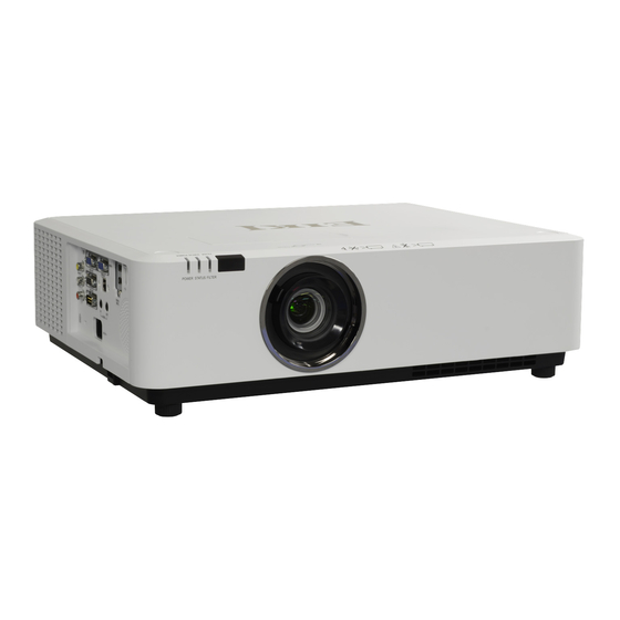
- Page 1 HLD Long Throw LCD Projector Service Manual Model: EK-350 Series...
-
Page 2: Table Of Contents
Content Content................ 2 Safety instruction ............3 Key lock, PIN code lock reset…………………………..8 Indicator and projector state……………..……...……...9 Maintenance and cleaning......... 10 Reset the filter counter…………………………………12 How to check the light source usage time….…...……13 Mechanical disassembly..........14 Service Mode............26 To enter Service Mode……………...……... -
Page 3: Safety Instruction
Safety instruction Technicians need to read and follow the "safety precautions" and "important safety tips" strictly in the service manual in the maintenance process. Caution The service manual is only for experienced technicians, rather than the general public. The service manual does not include the warning about the non-technicians or to inform the danger they may occur in the maintenance process. - Page 4 Safety instruction FCC Caution Note: This equipment has been tested and found to comply with the limits for a Class A digital device, pursuant to Part 15 of the FCC Rules. These limits are designed to provide reasonable protection against harmful interference in a residential installation.
- Page 5 Safety instruction Safety precautions 1.1 General policy: – Do not attempt to make a circuit modification for the sake of safety for long. – Unplug the power cord from the power outlet before removing the projector. – Please use the random supply line correctly, and make sure that the line must be earthed. –...
- Page 6 Safety instruction The projector has the following security operation circuit protection functions. If there is any abnormal in the inside of the projector, one of the following protection circuit action will make your projector shut down automatically . Cover switch When the top case is removed or not fully closed, the cover switch will turn off the projector.
- Page 7 Standby mode instruction The projector has three kinds of standby mode, namely Network mode, Normal mode and Eco mode. For each standby mode, the follow-ing functions will be limited as shown in the table. Please switch to Standby mode on the Setting menu. Network mode..Select standby mode with limited network.
-
Page 8: Key Lock, Pin Code Lock Reset
Key lock, PIN code reset This projector provides Key lock and PIN code lock and LOGO PIN code lock ensure your projector’s operation safety. Only when users enter the correct password can you open your projector when you has set up the three security fea- tures.You won't start the projector without password. -
Page 9: Indicator And Projector State
Indicator and projector status When the temperature inside the projector is too high or the cooling fan stops rototating or loss of power , the projector will shut down automatically. LED indicator POWER indicator – The power indicator turns steady red when your projector is in (Ready mode) –... -
Page 10: Maintenance And Cleaning
Maintenance and cleaning Before replacing components Please make sure to cut off the power and unplug the power cord from the power outlet when you make maintenance or replacement of components about your projector. Maintenance Clean casing of your projector ●... - Page 11 Maintenance and cleaning Clear the filter Clean the filter under the following circumstances. ● Clean the filter immediately whenever the replacement information displays or the Filter Warning indicator icon is on. Clean the filter immediately when the warning indicator is on as ●...
-
Page 12: Reset The Filter Counter
Reset the filter counter Reset the filter counter before you changing the filter. 1. Press MENU button and the OSD displays. Press button to select Expand menu, press button or OK. 2. Press button to select "Filter Counter", press button or OK. -
Page 13: How To Check The Light Source Usage Time
How to check the light source usage time It time to replace the light source when the light source usage time (Corresponding value) come to 20000 hours. Use the following formula to calculate the light source time . Light source usage time(Corresponding value)=Teco +Tnormal Tnormal : Usage time in normal mode Teco... -
Page 14: Mechanical Disassembly
Mechanical disassembly Remove the mechanical groups according to the following procedure. Screw Description The following steps are the basic processes and some unnecessary (Type D x L) mm steps may be ignored. Tapping screw-T Mechanical screw-M Note: Please return parts and screws where it belongs, as it ... - Page 15 Mechanical disassembly 1. T op cover disassembly : 1. Remove 12 screws A(T3x8), rotate counterclockwise to remove the lens decorative ring cover, then take out the top cover components. Top Case PN:63220131 Lens shift knob cover PN:63220134 First step Second step Third step 2.
- Page 16 Mechanical disassembly 4. Main board component disassembly : 1. Remove 3 screws A (T3X8), 2 screws B (M3X6), then take out the whole main board component. PCBA-MB_EK350U PN:63730148 -16-...
- Page 17 Mechanical disassembly 5. T erminal sheet, main board component disassembly : 1. Remove 1 screw B(T3X8), 2 C(M3X6) and 2 connector hexagon screws A(M3X6), then take out AV board. 2. Remove 4 D(T3X8), then take out the speaker and speaker rubber. 3.
- Page 18 Mechanical disassembly 6. Remote control component disassembly : 1. Remove 2 screws A(T3X8), then take out the remote control board component. PCBA_IR-B PN:63730151 PCBA_HDBaseT PN:63730130 7. Main board bracket disassembly : 1. Remove 1 screw A (M3X6), then take out the main board shield to ground. 2.
- Page 19 Mechanical disassembly 8.Speaker component disassembly 1. Remove 2 screws A (T3X8), 2 screws B (M3X6), then take out the speaker component. 2. Remove 4 screws C (T3X8), then take out the speaker rubber, speaker, air-intake fan and speaker bracket. Speaker_S5/S6 PN:63680005 FAN 5 PN:63260060...
- Page 20 Mechanical disassembly 11.LED light source component disassembly 1. Remove 2 screws A (T3X8), 2 screws B (M3X8), then take out the LED light source component. Note: The BLUE-LED radiator is with sharp edges and corners, please be careful when disassembling it. For safety reasons, please remove the ELMP_36_OstarLEB radiator in the area without sharp edges and...
- Page 21 Mechanical disassembly 13.Power board disassembly 1. Remove 4 screws A (M3x6), 3 screws B (M3x8). 2. Remove the wire clip, the bottom Power box, and the Power board. Power Supply PN:63730149 Fuse(F2001) PN:63740004 14.Bottom Power box component disassembly 1. Remove the bottom power board. 2.
- Page 22 Mechanical disassembly 15.HLD light source component disassembly 1. Remove 4 screws A (T3X8), 2 screws B (M3X8), then take out the LED light source component. Note: The HLD radiator is with sharp edges and corners, please be careful when ELMP_35_PhilipsHLD disassembling it.
- Page 23 Mechanical disassembly 18.Duct component and filter bracket component disassembly 1. Remove 7 screws A (T3x8), then take out the duct component. 2. Remove 4 screws B (T3x8), then take out the filter bracket component. 3. Remove 1 screws C (T2x10), then take out the 1 switches. 19.LED duct component disassembly 1.
- Page 24 Mechanical disassembly 20.Back remote control board and POWER socket disassembly 1. Remove 1 screw A (T3X8), then take out the back remote control board. 2. Remove 2 screws B (M3X6), then take out the socket shield metal. 3. Remove 2 screws C (T3X8), 1 screw D (M4X5), and the AC power socket . 21.Bottom case disassembly 1.
- Page 25 Adjustment after replacement parts ● : Adjustment : Check Remove / Replace parts LCD/ Condenser Polarizing POWER MAIN Prism board board lens(OUT) Optical Optical center adjustment ● adjustment Electrical ADC adjustment ● adjustment ● Fan voltage adjustment ● Check and set the screen type ...
-
Page 26: Service Mode
Service Mode To enter Service Mode Press and hold the “MENU” and button for more than 3 seconds. Then the Service Mode will display as follows. Service Mode G roup No . Input Computer 1 Item No . How to operate Group Data Press “MENU”... - Page 27 Service Mode Thermal Sensor 1 and 2 for GREEN-HLD (in HLD Ass'y W/I Packing) temp A temp B (under board) Thermal Sensor for BLUE-HLD ELMP_35_PhilipsHLD/ELMP_37_PhilipsHLD202: PN 22040006/22040008 Temp A: PN 63730152 Temp B: PN 63630009 Thermal Sensor for BLUE-HLD: PN 63630012 -27-...
- Page 28 Service Mode If you get the Error Code from 3200 to 3455, you can look for the comment in Driver Fault Mode as follows: Error Code 3200 : the comment of Driver State 0 Error Code 3201 : the comment of Driver State 1 Error Code 3202 : the comment of Driver State 2 Error Code 3455 : the comment of Driver State 255 Similarly, you can have the comments on Error Code from 3500 to...
-
Page 29: Adjustment After Replacement Parts
Adjustment after replacement parts Note: The circuit has been accurately adjusted at the factory. Do not attempt to adjust the following circuit as it may cause serious damage to property and product safety unless you have to adjust it during maintenance. Before adjustment, please turn on the projector to preheat at least 10 minutes. - Page 30 Adjustment after replacement parts 2.Fan voltages adjustment Equipment Digital voltmeter 1. Enter service mode. 2. Select the item 250. According to the following adj. item to change the value of the test value. group-Item Test point Adj. value 4.0 ±0.1Vdc 250 - 0 FAN-A1 12.5 ±0.1Vdc...
- Page 31 Adjustment after replacement parts 5.Keystone correction Input signal No signal 1.Adjust the pad to the minimum angle and place the projector horizontally. Enter service mode. 2. Select group 102 item 3 and change its value from 0 to 5. 3. Press the SELECT button for keystone correction. 4.
-
Page 32: Trouble Shooting
Trouble shooting Light indicator and projector status Light indicator indicates the projector status. If you have met kinds of unexpected problems when you operate the projector, please do as the following table says to check the operation of the projector. Check light indicator to learn status of your projector to ensure your projector in the best state. - Page 33 Trouble shooting No power We can indentify the abnormal area through light indicator status. Connect the AC power cord, press button to check light indicator. - All light indicators will be off indicates the main board abnormal. Please check the main board circuit and component.
- Page 34 Trouble shooting Power on abnormal Follow the steps below for check: Check the main board Power abnormal 16V_MCU and the power The STANDBY Check fuses and Power board. in Standby mode. indicator turns off (p.39) Check 3.3V_MCU. Check IC2005 and its loop. (p.39) (p.39) 1.
- Page 35 Trouble shooting Image display abnormal Check the image as the following steps. Singal input ; but no Check signal processing and LCD drive. image display Check the S16V power supply and peripheral device loop. (P.39) Check the connection between the main board to PANEL board and the power supply of Panel board.
- Page 36 Trouble shooting No sound Follow the steps below for check: Check whether it has au- 1. Check whether the speaker cable is plugged in or broken. dio signal output to pin 1/2 2. Ckeck whether the speaker is damaged or not. and 43/44 for IC5202.
- Page 37 Trouble shooting Before calling your dealer or service center for assistance, check the items below once again. - Make sure you have properly connected the projector to peripheral equipment. - Make sure all equipment is connected to the AC outlet and the power is turned on. - If the projector does not project an image when it is connected to a PC, restart the PC.
- Page 38 Trouble shooting No Sound - Check the audio cable connection from audio input source. - Adjust the audio source. - Press the VOLUME + button. - Press the Mute button. - When the AUDIO OUT is plugged in, the projector’s built-in speaker is not available.
- Page 39 Trouble shooting EK-350 trouble shooting Page IC Ioction IC model IC PIN# What volts are norml/NG Main board(SD,PIN9) Main board(SD,PIN9) ECO Stand by:11.5V(±5%);POWER ON:16.5V(±5%) 16V MCU Main board (SD,PIN9) IC2005(L2019 PIN2) 3.3V(±5%) IC2005 3.3V MCU IC2005 (PIN2) 3.3V(±5%) IC2005 IC2005(L2019 PIN2) IC2005 (PIN2) -39-...
- Page 40 Trouble shooting Page IC Ioction IC model IC PIN# What volts are norml/NG Y5008(16MHZ) (Y5008 PIN2) 16MHZ Y5008 (PIN2) IC 3001 IC3001(PIN31) VP-P 0.7V IC3001 (PIN31) 5V(±5%) IC 2008 IC2008(L2023 PIN2) IC 2008 (PIN2) -40-...
- Page 41 Trouble shooting Page IC Ioction IC model IC PIN# What volts are norml/NG IC 3001 IC3001(PIN35 or PIN36) VP-P 0.7V 35 S-Video RAI1 (PIN35 or PIN36) IC 3001 IC3001(PIN31) VP-P 0.7V S-Video GAI1 (PIN31) PIN1,2,63,64 have signal IC 4001 IC4001(PIN1,2,63,64) IC4001 (HDMI SW IC) (PIN1,2,63,64)
- Page 42 Trouble shooting Page IC Ioction IC model IC PIN# What volts are norml/NG L5004(10UH) AV BOARD(L5004 PIN2) 12V(±5%) L5004 (PIN2) AV BOARD(Q3043 B channel) Q3043(2SC4617) B Channel Close,SPEAKER no Sounds Q3043 (B channel) -42-...
-
Page 43: Appendix-Technical Specification
Appendix Technical Speci ications Mechanical properties Dimensions (W×H×D ) 460mmx355mmx143mm Net Weight Adjustable 10.0 Kg foot 5˚ LCD resolution 0.76" TFT LCD system EK-350U:1920x1200 LCD resolution Compatible signals PAL, SECAM, NTSC, NTSC4.43, PAL-60, PAL-M and PAL-N Color standard 480i, 480p, 576i, 576p, 720p, 1080p and 1080i HDTV signal Horizontal frequency: 15–100 KHz;... -
Page 44: Appendix-Serial Control
Serial con Appendix Serial control The <Serial Input> terminal of the projector is in accordance with RS-232C, so the projector can be connected to the computer and controlled by the computer. Connection Projector port D-Sub 9 pin (Male) D-Sub 9 pin (Female) Communication cable (Cross type) The pin layout and signal D-Sub 9 pin (Male) -
Page 45: Appendix-Rs232 Control Mode
Appendix Serial control RS232 control mode Serial connection 1.1 Port setting Projector Setpoint Communication method Asynchronous communication Communication rate 19200 Length 8-bit Parity check Stop position Flow control 1.2 Connection mode Can only use RS232 serial cross connect PC and projector. VGA terminal Projector terminal CD 1... -
Page 46: Appendix-Rs232 Control Commands
Appendix Serial control RS232 Control commands 2. Basic commands Distinguish the letter case.and enter Each command ends with [CR] (enter) . Command Option Command Option POWER ON Video POWER OFF(Immediatly) Component POWER OFF S-Video HDMI1 Network HDMI2 (MHL) Memory Viewer VGA IN 1 USB Display HDBaseT... - Page 47 Appendix Serial control 2.4 HDMI 1 command Command “C36”[CR] Details Select HDMI Input. Return Value Receive Successfully [ACK][CR] Receive Unsuccessfully “ ? ” [CR] 2.5 VGA IN 1 command Command “C05”[CR] Details Select VGA IN 1 Input Return Value Receive Successfully [ACK][CR]...
- Page 48 Appendix Serial control 2.9 Network command Command “C15”[CR] Details Select Network Input . Return Value Receive Successfully [ACK][CR] Receive Unsuccessfully “ ? ” [CR] 2.10 Memory Viewer command Command “C16”[CR] Details Select Memory Viewer Input . Return Value Receive Successfully [ACK][CR]...
- Page 49 Appendix Serial control 2.14 HD-BaseT command Command “C32”[CR] Details Select HDBaseT Input . Return Value Receive Successfully [ACK][CR] Receive Unsuccessfully “ ? ” [CR] Note: [ACK] "CR" is the return value for receiving valid commands. -49-...
-
Page 50: Appendix-Parts Location Diagram
Appendix Parts location diagram Important safety instruction components identified by international symbol identifies hold the special security features. Please use the specified model for replacement . Please make sure the parts list and the service code in structural parts list diagram before ordering repair parts. -50- SPL-1... - Page 51 Parts location diagram Parts location diagram Top cover components Lens shift knob cover Top Case PN:63220134 PN:63220131 INDEX PART NAME PART CODE CAB_TOP-AMBER 440038300 DOOR_KNOB_LNS_SFT-AMBER 440038500 ARM_DOOR_KNOB_LNS_SFT- 410017700 AMBER DEC_INLAY_LED-CITRINE 440035300 DEC_RC_LED-CITRINE 440035400 Filter components Sponge for filter box PN:63340079 FAN_L PN:63260057 PCBA_Sensor...
- Page 52 Parts location diagram Bottom cover components INDEX PART NAME PART CODE CAB_BTM-AMBER 440038400 PN:63260059 FAN PN:63260060 SHIELD_BTM-AMBER 430017100 ADJUSTER_FOOT-AMBER 440042500 RUBBER_ADJ FOOT_front-amber 440042800 RUBBER_ADJ_FOOT_back-amber 440042700 RMS-3V01 440028900 WCM-0017 440043200 SHIELD_AC_SOCKET-AMBER 430027800 FAN PN:63260058 SCREW M4*5 420001100 AC POWER SOCKET back_IR-amber 440039500 PCBA_IR-B BACK IR PWB...
- Page 53 Parts location diagram Terminal component PCBA-MB_EK350U PN:63730148 INDEX PART NAME PART CODE 63730148 PCBA-MB_EK350U PCBA_AV Board 63730150 PCBA_AV Board PN:63730150 Speaker_S5/S6 63680005 Speaker_S5/S6 PN:63680005 Optical engine component ELMP_35_PhilipsHLD PN:22040006 ELMP_36_OstarLEB PN:22040007 INDEX PART NAME PART CODE Optical Engine_EK350U 63010058 Lens shift knob 63220142 ELMP_35_PhilipsHLD 22040006...
- Page 54 Parts location diagram Bottom power box component INDEX PART NAME PART CODE POWER PWB HLD_POW_PL_BTM-amber 430016900 SPACE_SHEET_POWER_SIDE_1-AMBER 410017500 Ballast_HLD SPACE_SHEET_POWER_SIDE_2-AMBER 410017600 SHEET-CAB_TOP_BK_R-FALCON 410008600 PN:63670032 SHEET_CAB_TOP_BK_L-FALCON 410008400 SPACE_SHEET_SIDE_HLD_SINK-AMBER 410017900 55 RMS-3V01 440028900 HD DRIVE PWB HLD_POW_PL_TOP-AMBER 430017000 lead clamper _WCM-0017 440043200 Power Supply PN:63730149 47...
- Page 55 Appendix PCB Diagram Important safety instruction components identified by International symbol identifies hold the special security features. Please use the specified model for replacement . Low voltage and high voltage warning The power supply circuit includes a circuit unit to seperate the power supply from ground. ●...
-
Page 56: Appendix-Pcb Diagram
Appendix PCB Diagram Amber WUXGA main board Main board PcB (A) Main board PcB (B) 主板 PCB 板(B) -56-... - Page 57 Appendix PCB Diagram Power board PCB(A) Power board PCB(B) LED+RC(A) LED+RC(B) -57-...
- Page 58 Appendix PCB diagram AV board (A) AV board (B) DIA-4 -58-...
-
Page 59: Appendix-Schematic Diagram
Appendix Schematic diagram HLD WUXGA (EK-350) MianBoard Block Diagrams S16V NTC-DDR2- 1G-G-R20 POWER 16V_PANEL POWER MODULE SUPPLY LCD Driver 16V_FAN CXA3832 VIDEO LCD Driver CXA3832 VGA1 IN THS7347 IC3001 CXD3553DB R/G/B/H/V VGA2 IN IC9005 LCD Driver CXA3832 FR9888 VGA OUT FR9888 1.2V IC5012... -
Page 60: Appendix-Chassis Block Diagram
Appendix chassis block diagram HDMI loop control diagram IC4001 IT66332 HDMI1 IC4005 7,10 HDMI_L Audio D/A HDMI_R CS4344 HDMI IC1001 PW878 HDMI2 -60-... - Page 61 Appendix chassis block diagram MCU board loop control diagram Q5102 MOSFER 3.3V ON_PHY Q2024 3_3V ON_MCU MOSFER ICSPDAT P_ON/OFF ICSPCLK POWRE_ON /MCLR IC1007 PIC18F45K22 MIMDIO SUB CPU MIMDC 3_3SDA 3_3SCL P_KEY KEY1-KEY3 ADC2-ADC0 Control IC1001 PW878 RC/BEHIN -61-...
- Page 62 Appendix chassis block diagram AV loop control diagram IC5005 P5002 Audio P5003 Speaker PC L/R IN PC L/R OUT IC5002 PT-2830 VIDEO AUDIO IN Speaker (RCA*3) R/C_REAR RXD/TXD IC4019 RS232 SP323EEY-L -62-...
- Page 63 Appendix chassis block diagram Fan loop control diagram FAN loop control diagram 风扇控制电路 Fan_16V Q303 IC300 FANA_D FR988 D3011 Q300 FAND_D D300 IC300 8 F R988 FAN_S D300 8 Q3361 FANB_D IC325 D301 0 F R988 Q328 D300 FANC_D IC328 FR988 D300 5 Q3011...
- Page 64 E89A1679 ~ E89A1747 E8ZA1928 ~ E8ZA1997 EK-350U S/N: E87Axxxx ~ (except E89A1679 ~ E89A1747 / Shielding for bottom_HLD202 63210038 E8ZA1928 ~ E8ZA1997 ) Compatible with all S/Ns Lens protection cover (GP) 63340086 Packing Carton 63340076 Optional Remote Control for EK-350 series 63910027...
Need help?
Do you have a question about the EK-350 Series and is the answer not in the manual?
Questions and answers