Eiki EK-300U Service Manual
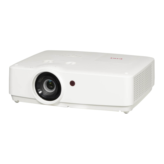
Lcd multi-media projector
Hide thumbs
Also See for EK-300U:
- Owner's manual (84 pages) ,
- Service manual (35 pages) ,
- Quick start manual (2 pages)

Subscribe to Our Youtube Channel
Related Manuals for Eiki EK-300U


Summary of Contents for Eiki EK-300U
- Page 1 LCD Multi-media Projector Service Manual EIKI Model Name: EK-300U EK-301W EK-302X EK-303U EK-305U EK-306U EK-307W EK-308U EK-309W V 20.0...
-
Page 2: Table Of Contents
Content Content................2 Safety instruction..............3 Key lock, PIN code lock reset...……………..…………….…. 8 Filter Counter reset……….………………...………….……..9 Maintenance and cleaning..........10 How to check the lamp usage time........11 Lamp Replacement.............12 Order Replacement lamp……………………………….……………..12 Lamp Replacement………………………………………………..…...13 Lamp Counter reset………………….……………………………..…..14 Warning Indicator..............15 Indicator and projector state..........16 Trouble shooting..............17 Mechanical disassembly.............21 Service Mode…….……………..…………….……..…...29... -
Page 3: Safety Instruction
Safety instruction Please read this manual completely before installing Safety precautions and operating the projector. The projector provides many convenient features Caution: ﹒ The projector must be grounded. and functions. Proper operation may enable you to ● Do not expose the projector to raindrops fully utilize the features and keep it in good condition. - Page 4 Safety instruction Air circulation Installing the projector properly Vents in the cabinet are provided for ventilation. Please set the projector on nearly-level. To ensure reliable operation of the product and Be sure to install the projector properly. to protect it from overheating, these openings Improper installation may reduce the lamp must not be blocked or covered.
- Page 5 Safety instruction safety precautions 1.1 General Policy -Do not attempt to make a circuit modification for the sake of safety for long time. -Unplug the power cord from the power outlet before removing the projector . -Please use the random supply line correctly, and make sure that the line must be earthed. -Use insulation transformer on the ac power cord before maintenance.
- Page 6 Safety instruction Circuit protection The projector has the following security operation circuit protection functions. If there is any abnormal in the inside of the projector, one of the following projection circuit action will make your projector shut down automatically. Thermal switch - The thermal switch inside the projector is used to detect abnormal temperature inside the projector.
- Page 7 х: No Control ∆: Power On command Only √: All commands are active *х: Power On command is active with “Wake On LAN” software. • The “Wake On LAN” software and its manual can be downloaded from EIKI global website https://global.eiki.com/...
-
Page 8: Key Lock, Pin Code Lock Reset
Key lock, PIN code lock reset This projector provides Key lock and PIN code lock and LOGO PIN code lock ensure your projector’s operation safety. Only when users enter the correct password can you open your projector when you has set up the three security features.You won't start the projector without password. In case of the above issues, please reset such three security features according to the following reset procedure, and then re-check. -
Page 9: Filter Counter Reset
Filter Counter reset Cleaning the filter The air filter prevents dust from accumulating on the surface of the optical elements inside the projector. Should the air filter become clogged with dust particles, it will reduce cooling fans’ effectiveness and may result in a buildup of internal heat and adversely affects the life of the projector. -
Page 10: Maintenance And Cleaning
Maintenance and cleaning Clean the projector lens Unplug the AC power cord before cleaning. Gently wipe the projection lens with a cleaning cloth that contains nonabrasive camera lens cleaner, or use a lens cleaning paper or commercially available air blower to clean the lens. -
Page 11: How To Check The Lamp Usage Time
How to check the lamp usage time It's time to replace the lamp when the lamp usage time (Corresponding value) come to 4,000 hours. Use the following formula to calculate the lamp time . Lamp usage time(Corresponding value)=Teco +Tnormal x (4/3) Tnormal : Usage time in normal mode Teco... -
Page 12: Lamp Replacement
Lamp Replacement Order Replacement lamp Replacement lamp can be ordered through your dealer. When ordering a projection lamp, give the following information to the dealer. Replacement Lamp Model No.: 22040001, (EK309W/308U) 22040013 LAMP HANDLING PRECAUTIONS This projector uses a high-pressure lamp which must be handled carefully and properly. Improper handling may result in accidents, injury,... -
Page 13: Lamp Replacement
Lamp Replacement When the projection lamp of the projector Lamp replacement icon reaches its end of life, the Lamp replacement icon appears on the screen. Replace the lamp Lamp replacement with a new one of the same type promptly. The timing when the lamp replacement icon appears is depending on the lamp mode. -
Page 14: Lamp Counter Reset
Lamp Replacement If the filter is blocked by dust, the effect of cooling fan will be reduced, and heat accumulate in the projector, service life and the life of the lamp will be shortened. Cleaning filter is suggested after lamp replacement. -
Page 15: Warning Indicator
WARNING indicator The WARNING indicator shows the state of the function which protects the projector. Check the state of the WARNING indicator to take proper maintenance. The projector is shut down and the WARNING indicator is flashing red WARNING indicator When the temperature inside the projector exceeds the normal temperature, the projector is automatically shut down to protect internal... -
Page 16: Indicator And Projector State
Indicator and projector state Check the indicator to know about the state of projector Indicator State of projector POWER WARNING (Green/Red/ (Red) Yellow) Projector is in Off status (without AC power supply). Projector is in standby status. Press Standby button to turn it on. Projector is in normal status. -
Page 17: Trouble Shooting
Trouble shooting When the temperature inside the projector is too high or the cooling fan stops rototating or loss of power ,the projector will shut down automatically. POWER indicator - the power indicator turns steady red when the projector is in standby mode, - the power indicator turns steady green during the working time. - Page 18 Trouble shooting Image display abnormal Check the image as the following steps. Signal input ; but Check signal processing and LCD driver board. no image display Check the power supply. Check the connection between the main board to LCD driver board and the power supply of LCD driver board.
- Page 19 Trouble shooting Before calling your dealer or service center for assistance, check the items below once again. - Make sure you have properly connected the projector to peripheral equipment. - Make sure all equipment is connected to the AC outlet and the power is turned on. - If the projector does not project an image when it is connected to a PC, restart the PC.
- Page 20 Trouble shooting No Sound - Check the audio cable connection from audio input source. - Adjust the audio source. - Press the VOLUME + button. - Press the Mute button. - When the AUDIO OUT is plugged in, the projector’s built-in speaker is not available.
-
Page 21: Mechanical Disassembly
Mechanical Disassembly Mechanical disassembly should be made following s crew Description procedures in numerical order. (Type D x L) mm Following steps show the basic procedures, therefore Tapping screw-T mechanical screw-m unnecessary steps may be ignored. Caution The parts and screws should be placed exactly the same position as the original otherwise it may cause loss of performance and product safety. - Page 22 Mechanical Disassembly Dust filter, Top Case removal 1. Open dust filter cover and remove Dust filter. 2. Loosen 1 screw B, 11 screws A and remove Lamp cover and Top case . The chapter is only designed to show exploded image of the projector. For updated part numbers, please refer to RSPL.
- Page 23 The chapter is only designed to show exploded image of the projector. For updated part numbers, please refer to RSPL PCBA-LCD Driver Boar PCBA-LCD Driver Board EK-301W/302X /307W/309W EK-300U/303U/305U/ PN: 63730080 306U/308U PN:63730092 PCBA - Main Board EK300U/ EK303U/ EK305U PN:63730093...
- Page 24 Mechanical Disassembly Optical Engine(OE) and Speaker disassembly Loosen 7 screws and remove OE The chapter is only designed to show exploded image of the projector. For updated part numbers, please refer to RSPL Optical Engine -EK300U/ EK303U/ EK305U PN:63010029 Optical Engine -EK301W PN:63010030 Optical Engine -EK302X PN:63010031 OE-WXGA-EK-307W PN:63010066 OE-WUXGA-EK-306U PN:63010067...
- Page 25 Mechanical Disassembly (EK-300U/301W/302X/303U/305U/306U/307W) Fan of OE & Lamp duct disassembly 1. Loosen 11 screws A, and remove OE Duct Ass'y 2. Loosen 3 screws C, and remove Fan of OE. The chapter is only designed to show exploded image of the projector.
- Page 26 Mechanical Disassembly (EK309W/308U) Fan of OE & Lamp duct disassembly 1. Loosen 11 screws A, and remove OE Duct Ass'y 2. Loosen 3 screws C, and remove Fan of OE. The chapter is only designed to show exploded image of the projector. For updated part numbers, please refer to RSPL Main board Description...
- Page 27 Mechanical Disassembly Fan Driver PCBA & Power supply and Ballast disassembly 1. Loosen 3 screws C, and remove Fan Driver PCBA 2. Loosen 5 screws A , 4 screws B and remove Power and Ballast Ass'y PCBA-IR Board PN: 63730088 PCBA-Fan Driver Board_CA PN: 63730096 Power supply...
- Page 28 Mechanical Disassembly Case of Bottom disassembly Take off 10 screws and shield metal of BTM case. Take off adjust foot and it's button. The chapter is only designed to show exploded image of the projector. For updated part numbers, please refer to RSPL Case_BTM_CA PN:63220091 BTM-Case_CAX PN:63220154 (EK-308U/309W)
-
Page 29: Service Mode
Service Mode To enter Service Mode Press and hold the “MENU” and button for more than 3 seconds. Then the Service Mode will display as follows. Service Mode How to operate Input Computer 1 Press “MENU” button to select the “Group” item, and press ▲... -
Page 30: Appendix-Technical Specification
Appendix Technical Speciications (EK-300U/301W/302X/303U/305U/306U/307W) LCD system XGA: 0.63" TFT, active matrix, 3-panel WXGA: 0.59" TFT, active matrix, 3-panel WUXGA: 0.64" TFT, active matrix, 3-panel LCD resolution XGA: 1024X768 /WXGA: 1280X800 / WUXGA: 1920X1200 Compatible signals PAL, SECAM, NTSC, NTSC4.43, PAL-M, PAL-N and PAL60... - Page 31 Appendix Technical Speciications (For EK309W/308U) LCD system 0.64" TFT, active matrix, 3-panel LCD resolution WXGA: 1280X800 / WUXGA: 1920X1200 Compatible signals Color standard PAL, SECAM, NTSC, NTSC4.43, PAL-M, PAL-N and PAL60 480i, 480p, 576i, 576p, 720p, 1035i, 1080i and 1080p HDTV signal Scanning frequency Horizontal frequency: 15 kHz –100 KHz;...
-
Page 32: Appendix-Configuration Of Terminals
Appendix Conigurations of terminals VGA IN 1 terminal pin assignments and signal names YPbPr S-Video ----- DDC data HD/SYNC DDC clock VGA IN 2/VGA OUT terminal pin assignments and signal names ----- ----- DDC data HD/SYNC DDC clock RS232 terminal (D-SUB-9 pin) LAN terminal ----- TX +... -
Page 33: Appendix-Serial Control
Appendix Serial port The <Serial Input> terminal of the projector is in accordance with RS-232C, so the projector can be connected to the computer and controlled by the computer. Connection Projector port D-Sub 9 pin (Male) D-Sub 9 pin (Female) Communication cable (Cross type) The pin layout and signal D-Sub 9 pin (Male) -
Page 34: Appendix-Rs232 Control Mode
Appendix RS232 control mode Serial connection 1.1 Port setting Projector Setpoint Communication method Asynchronous communication Communication rate 19200 Length 8-bit Parity check Stop position Flow control 1.2 Connection mode Can only use RS232 serial cross connect PC and projector. VGA terminal Projector terminal CD 1 1 N.C. -
Page 35: Appendix-Rs232 Control Commands
Appendix RS232 control commands Distinguish the letter case, and enter Each command ends with [CR] (enter) . Command Option Command Option POWER ON Video POWER OFF(Immediatly) Component POWER OFF S-video HDMI1 Network HDMI(MHL) Memory Viewer VGA IN 1 USB Display VGA IN 2 2.1 POWER ON command Command... - Page 36 Appendix Serial control 2.4 HDMI 1 command Command “C36"[CR] Details Select HDMI Input. [ACK][CR] Return Value Receive Successfully Receive Unsuccessfully “?" [CR] 2.5 VGA IN 1 command Command “CO5"[CR] Details Select VGA IN 1 Input Return Value Receive Successfully [ACK][CR] Receive Unsuccessfully “?"...
- Page 37 Appendix Serial control 2.9 Network command Command “C15"[CR] Details Select Network Input . Return Value Receive Successfully [ACK][CR] Receive Unsuccessfully “?" [CR] 2.10 Memory Viewer command Command “C16"[CR] Select Memory Viewer Input . Details Return Value Receive Successfully [ACK][CR] Receive Unsuccessfully “?"...
-
Page 38: Appendix-Pcb Diagrams
Appendix PCB diagram Main board PCB ( A ) Main board PCB ( A ) IUJIUJ�l�-l!J -�i� - 1!1 lj�Jli ll�I� E�1� � � � � ""'- •• ,1 "' '' " ]� 1J I""" l• m, � � a """... - Page 39 Appendix PCB diagram Only for XGA&WXGA series: LCD drive board (A) LCD drive board (A) MARK9 1 3 8 1 00 3 7 0 M 1 2 3 4 5 6 7 8 9 10 11 12 1 2 3 4 t �...
- Page 40 Appendix PCB diagram AC Filter board AC Filter board Power board (A) Power board (A) Power board (B) Power board (B)
- Page 41 Appendix PCB diagram Terminal (A) Terminal (A) D , . , . Terminal (B) Terminal (B) Q1207 l i lt ; IQJ0451� ..,: � �� � L40JO; � Key button and LED board (A) Key button and LED board (A) '"...
- Page 42 Appendix PCB diagram Remote control board (A) Remote control board (A) (PCBA-IR Board PN:63730088) Remote control board (B) Remote control board (B) Temperature board (A) Temperature board (A) (PCBA-TempA PN:63730099) Temperature board (B) Temperature board (B) Note: Picture can suits XGA & WXGA & WUXGA series without any other description separately.
-
Page 43: Appendix-Schematic Diagram
Appendix Schematic diagram schematic diagram for XGA&WXGA... - Page 44 Appendix Schematic diagram schematic diagram for WUXGA...
- Page 45 Lens shift holder (GP) 63220143 Cable M/B to Power Board 63660017 Cable M/B to Fan Board 63660018 Packing Carton_EK-300 63340048 Remote Control EIKI logo 63910016 Power Cord 1830mm (US) 13650009 Power Cord 1830mm (Europe) 13650011 Power Cord 1830mm (Australia) 13650013 Optional...
Need help?
Do you have a question about the EK-300U and is the answer not in the manual?
Questions and answers