
Subscribe to Our Youtube Channel
Related Manuals for Daikin VRV 5 S Series


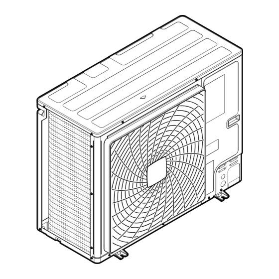
Summary of Contents for Daikin VRV 5 S Series
- Page 1 Installer and user reference guide VRV 5-S system air conditioner RXYSA4A7V1B RXYSA5A7V1B RXYSA6A7V1B RXYSA4A7Y1B RXYSA5A7Y1B RXYSA6A7Y1B...
-
Page 2: Table Of Contents
Table of contents Table of contents 1 About this document Meaning of warnings and symbols..........................2 General safety precautions For the installer ................................2.1.1 General ................................2.1.2 Installation site ............................... 2.1.3 Refrigerant — in case of R410A or R32......................2.1.4 Brine................................ - Page 3 Table of contents 10.2.2 Symptom: Cool/Heat cannot be changed over ..................... 47 10.2.3 Symptom: Fan operation is possible, but cooling and heating do not work ..........47 10.2.4 Symptom: The fan speed does not correspond to the setting..............47 10.2.5 Symptom: The fan direction does not correspond to the setting..............
- Page 4 Table of contents 18.1.5 Refrigerant piping length and height difference ................... 84 18.2 Connecting the refrigerant piping ..........................85 18.2.1 About connecting the refrigerant piping ....................... 85 18.2.2 Precautions when connecting the refrigerant piping..................85 18.2.3 Pipe bending guidelines ..........................86 18.2.4 To remove the spun pipes..........................
- Page 5 Table of contents 25 Maintenance and service 25.1 Maintenance safety precautions............................ 144 25.1.1 To prevent electrical hazards ......................... 145 25.2 Checklist for yearly maintenance of the outdoor unit....................146 25.3 About service mode operation............................146 25.3.1 To use vacuum mode ............................. 146 25.3.2 To recover refrigerant ............................
-
Page 6: About This Document
Preparation of the installation, reference data,… Detailed step-by-step instructions and background information for basic and advanced usage Format: Digital files on https://www.daikin.eu. Use the search function find your model. Latest revisions of the supplied documentation may be available on the regional Daikin website or via your dealer. - Page 7 About this document DANGER: RISK OF EXPLOSION Indicates a situation that could result in explosion. WARNING Indicates a situation that could result in death or serious injury. WARNING: FLAMMABLE MATERIAL CAUTION Indicates a situation that could result in minor or moderate injury. NOTICE Indicates a situation that could result in equipment or property damage.
-
Page 8: General Safety Precautions
WARNING Improper installation or attachment of equipment or accessories could result in electrical shock, short-circuit, leaks, fire or other damage to the equipment. ONLY use accessories, optional equipment and spare parts made or approved by Daikin unless otherwise specified. WARNING Make sure installation, testing and applied materials comply with applicable legislation (on top of the instructions described in the Daikin documentation). -
Page 9: Installation Site
General safety precautions CAUTION Do NOT touch the air inlet or aluminium fins of the unit. CAUTION ▪ Do NOT place any objects or equipment on top of the unit. ▪ Do NOT sit, climb or stand on the unit. NOTICE Works executed on the outdoor unit are best done under dry weather conditions to avoid water ingress. - Page 10 General safety precautions DANGER: RISK OF EXPLOSION Pump down – Refrigerant leakage. If you want to pump down the system, and there is a leak in the refrigerant circuit: ▪ Do NOT use the unit's automatic pump down function, with which you can collect all refrigerant from the system into the outdoor unit.
-
Page 11: Brine
General safety precautions ▪ Either if the unit is factory charged with refrigerant or the unit is non-charged, you might need to charge additional refrigerant, depending on the pipe sizes and pipe lengths of the system. ▪ ONLY use tools exclusively for the refrigerant type used in the system, this to ensure pressure resistance and prevent foreign materials from entering into the system. -
Page 12: Water
General safety precautions 2.1.5 Water If applicable. See the installation manual or installer reference guide of your application for more information. NOTICE Make sure water quality complies with EU directive 2020/2184. 2.1.6 Electrical DANGER: RISK OF ELECTROCUTION ▪ Turn OFF all power supply before removing the switch box cover, connecting electrical wiring or touching electrical parts. -
Page 13: Gas
General safety precautions CAUTION ▪ When connecting the power supply: connect the earth cable first, before making the current-carrying connections. ▪ When disconnecting the power supply: disconnect the current-carrying cables first, before separating the earth connection. ▪ The length of the conductors between the power supply stress relief and the terminal block itself MUST be as such that the current-carrying wires are tautened before the earth wire is in case the power supply is pulled loose from the stress relief. -
Page 14: Gas Exhaust
General safety precautions Boilers that use natural gas MUST be connected to a governed meter. Boilers that use liquid petroleum gas (LPG) MUST be connected to a regulator. The size of the gas supply pipe should under no circumstance be less than 22 mm. The meter or regulator and pipe work to the meter MUST be checked preferably by the gas supplier. - Page 15 General safety precautions ▪ BS 5440-2: 2009 Flueing and ventilation for gas appliances of rated input not exceeding 70 kW net (1st, 2nd and 3rd family gases) ▪ BS 5546: 2010 Specification for installation and maintenance of gas-fired water- heating appliances of rated input not exceeding 70 kW net ▪...
-
Page 16: Specific Installer Safety Instructions
Specific installer safety instructions 3 Specific installer safety instructions Always observe the following safety instructions and regulations. Installation site (see "17.1 Preparing the installation site" [ 72]) WARNING Follow the service space dimensions in this manual for correct installation of the unit. "28.1 Service space: Outdoor unit" [ 155]. - Page 17 Specific installer safety instructions CAUTION Do NOT vent gases into the atmosphere. WARNING Provide adequate measures to prevent that the unit can be used as a shelter by small animals. Small animals that make contact with electrical parts can cause malfunctions, smoke or fire.
-
Page 18: Instructions For Equipment Using R32 Refrigerant
Specific installer safety instructions WARNING ▪ If the power supply has a missing or wrong N-phase, equipment might break down. ▪ Establish proper earthing. Do NOT earth the unit to a utility pipe, surge absorber, or telephone earth. Incomplete earthing may cause electrical shock. ▪... - Page 19 WARNING Make sure installation, servicing, maintenance and repair comply with instructions from Daikin and with applicable legislation and are executed ONLY by authorised persons. WARNING If one or more rooms are connected to the unit using a duct system, make sure: ▪...
- Page 20 Specific installer safety instructions "16.3 To determine the charge limit" [ 65] to check if your system meets the requirement for charge limitation. RXYSA4~6A7V/Y1B Installer and user reference guide VRV 5-S system air conditioner 4P600330-1D – 2023.02...
-
Page 21: For The User
For the user RXYSA4~6A7V/Y1B Installer and user reference guide VRV 5-S system air conditioner 4P600330-1D – 2023.02... -
Page 22: User Safety Instructions
User safety instructions 4 User safety instructions Always observe the following safety instructions and regulations. In this chapter General....................................Instructions for safe operation............................... 4.1 General WARNING If you are NOT sure how to operate the unit, contact your installer. WARNING This appliance can be used by children aged from 8 years and above and persons with reduced physical, sensory or mental capabilities or lack of experience and knowledge if... -
Page 23: Instructions For Safe Operation
User safety instructions ▪ Units are marked with the following symbol: This means that electrical and electronic products may NOT be mixed with unsorted household waste. Do NOT try to dismantle the system yourself: dismantling the system, treatment of the refrigerant, of oil and of other parts MUST be done by an authorised installer and MUST comply with applicable legislation. - Page 24 User safety instructions CAUTION It is unhealthy to expose your body to the air flow for a long time. CAUTION To avoid oxygen deficiency, ventilate the room sufficiently if equipment with burner is used together with the system. WARNING This unit contains electrical and hot parts. WARNING Before operating the unit, be sure the installation has been carried out correctly by an installer.
- Page 25 User safety instructions WARNING ▪ Do NOT modify, disassemble, remove, reinstall or repair the unit yourself as incorrect dismantling or installation may cause an electrical shock or fire. Contact your dealer. ▪ In case of accidental refrigerant leaks, make sure there are no naked flames.
- Page 26 User safety instructions WARNING The unit is equipped with a refrigerant leak detection system for safety. To be effective, the unit MUST be electrically powered at all times after installation, except for maintenance. RXYSA4~6A7V/Y1B Installer and user reference guide VRV 5-S system air conditioner 4P600330-1D –...
-
Page 27: About The System
About the system 5 About the system The VRV 5-S uses R32 refrigerant which is rated as A2L and is mildly flammable. For compliance with the requirements for enhanced tightness refrigerating systems and IEC60335-2-40 the installer must take extra measures. For more information, "3.1 Instructions for equipment using R32 refrigerant" [ 18]. -
Page 28: User Interface
User interface 6 User interface CAUTION ▪ NEVER touch the internal parts of the controller. ▪ Do NOT remove the front panel. Some parts inside are dangerous to touch and appliance problems may happen. For checking and adjusting the internal parts, contact your dealer. -
Page 29: Operation
Operation 7 Operation In this chapter Before operation ..................................Operation range..................................Operating the system ................................7.3.1 About operating the system ..........................7.3.2 About cooling, heating, fan only, and automatic operation ................. 7.3.3 About the heating operation ..........................7.3.4 To operate the system (WITHOUT cool/heat changeover remote control switch) ..........7.3.5 To operate the system (WITH cool/heat changeover remote control switch)............. -
Page 30: Operation Range
Operation This operation manual is for the following systems with standard control. Before initiating operation, contact your dealer for the operation that corresponds to your system type and mark. If your installation has a customised control system, ask your dealer for the operation that corresponds to your system. Operation modes (depending on indoor unit type): ▪... -
Page 31: About The Heating Operation
Operation 7.3.3 About the heating operation It may take longer to reach the set temperature for general heating operation than for cooling operation. The following operation is performed in order to prevent the heating capacity from dropping or cold air from blowing. Defrost operation In heating operation, freezing of the outdoor unit's air cooled coil increases over time, restricting the energy transfer to the outdoor unit's coil. -
Page 32: To Operate The System (With Cool/Heat Changeover Remote Control Switch)
Operation 7.3.5 To operate the system (WITH cool/heat changeover remote control switch) Overview of the changeover remote control switch FAN ONLY/AIR CONDITIONING SELECTOR SWITCH Set the switch to for fan only operation or to for heating or cooling operation. COOL/HEAT CHANGEOVER SWITCH Set the switch to for cooling or to heating... -
Page 33: To Use The Dry Program (Without Cool/Heat Changeover Remote Control Switch)
Operation ▪ The micro computer automatically determines temperature and fan speed (cannot be set by the user interface). ▪ The system does not go into operation if the room temperature is low (<20°C). 7.4.2 To use the dry program (WITHOUT cool/heat changeover remote control switch) To start 1 Press the operation mode selector button on the user interface several times and select... -
Page 34: Adjusting The Air Flow Direction
Operation NOTICE Do not turn off power immediately after the unit stops, but wait for at least 5 minutes. 7.5 Adjusting the air flow direction Refer to the operation manual of the user interface. 7.5.1 About the air flow flap Double flow + multi-flow units Wall-mounted units For the following conditions, a micro computer controls the air flow direction... -
Page 35: Setting The Master User Interface
Operation 7.6 Setting the master user interface 7.6.1 About setting the master user interface a Heat pump outdoor unit b Refrigerant piping c VRV direct expansion (DX) indoor unit d Remote controller in normal mode e Remote controller in alarm only mode f Remote controller in supervisor mode (mandatory in some situations) When the system is installed as shown in the figure above, it is necessary to designate one of the user interfaces as the master user interface. -
Page 36: Energy Saving And Optimum Operation
Energy saving and optimum operation 8 Energy saving and optimum operation Observe the following precautions to ensure the system operates properly. ▪ Adjust the air outlet properly and avoid direct air flow to room inhabitants. ▪ Adjust the room temperature properly for a comfortable environment. Avoid excessive heating or cooling. -
Page 37: Available Main Operation Methods
Energy saving and optimum operation 8.1 Available main operation methods Basic The refrigerant temperature is fixed independent from the situation. It corresponds to the standard operation which is known and can be expected from/ under previous VRV systems. Automatic The refrigerant temperature is set depending on the outdoor ambient conditions. As such adjusting the refrigerant temperature to match the required load (which is also related to the outdoor ambient conditions). -
Page 38: Maintenance And Service
Maintenance and service 9 Maintenance and service WARNING The unit is equipped with a refrigerant leak detection system for safety. To be effective, the unit MUST be electrically powered at all times after installation, except for maintenance. WARNING NEVER replace a fuse with a fuse of a wrong ampere ratings or other wires when a fuse blows out. -
Page 39: After A Long Stop Period
Maintenance and service 9.1 After a long stop period E.g., at the beginning of the season. ▪ Check and remove everything that might be blocking inlet and outlet vents of indoor units and outdoor units. ▪ Clean air filters and casings of indoor units. Contact your installer or maintenance person to clean air filters and casings of the indoor unit. -
Page 40: After-Sales Service And Warranty
Maintenance and service WARNING ▪ The refrigerant inside the unit is mildly flammable, but normally does NOT leak. If the refrigerant leaks in the room and comes in contact with fire from a burner, a heater, or a cooker, this may result in fire, or the formation of a harmful gas. ▪... -
Page 41: Recommended Maintenance And Inspection Cycles
Maintenance and service WARNING ▪ Do NOT modify, disassemble, remove, reinstall or repair the unit yourself as incorrect dismantling or installation may cause an electrical shock or fire. Contact your dealer. ▪ In case of accidental refrigerant leaks, make sure there are no naked flames. The refrigerant itself is entirely safe, non-toxic and mildly flammable, but it will generate toxic gas when it accidentally leaks into a room where combustible air from fan heaters, gas cookers, etc. - Page 42 Maintenance and service ▪ Power fluctuation is high (voltage, frequency, wave distortion, etc.) (the unit cannot be used if power fluctuation is outside the allowable range). ▪ Bumps and vibrations are frequent. ▪ Dust, salt, harmful gas or oil mist such as sulphurous acid and hydrogen sulfide may be present in the air.
-
Page 43: Troubleshooting
Troubleshooting 10 Troubleshooting If one of the following malfunctions occur, take the measures shown below and contact your dealer. WARNING Stop operation and shut OFF the power if anything unusual occurs (burning smells etc.). Leaving the unit running under such circumstances may cause breakage, electrical shock or fire. - Page 44 Troubleshooting Malfunction Measure The system operates but ▪ Check if air inlet or outlet of outdoor or indoor cooling or heating is unit is not blocked by obstacles. Remove any insufficient. obstacles and make sure the air can flow freely. ▪...
-
Page 45: Error Codes: Overview
Troubleshooting 10.1 Error codes: Overview In case a malfunction code appears on the indoor unit user interface display, contact your installer and inform the malfunction code, the unit type, and serial number (you can find this information on the nameplate of the unit). For your reference, a list with malfunction codes is provided. - Page 46 Troubleshooting Main code Contents Electronic expansion valve malfunction (outdoor) Discharge temperature malfunction (outdoor) Abnormal suction temperature (outdoor) Refrigerant overcharge detection High pressure switch malfunction Fan motor trouble (outdoor) Ambient temperature sensor malfunction (outdoor) Pressure sensor malfunction Current sensor malfunction Discharge temperature sensor malfunction (outdoor) Suction temperature sensor malfunction (outdoor) De-icing temperature sensor malfunction (outdoor) Liquid temperature sensor (after subcool HE) malfunction...
-
Page 47: Symptoms That Are Not System Malfunctions
Troubleshooting Main code Contents Centralised address duplication Malfunction in communication centralised control device - indoor unit Auto address malfunction (inconsistency) Auto address malfunction (inconsistency) The error code is only shown on the user interface of the indoor unit where the error occurs. -
Page 48: Symptom: The Fan Direction Does Not Correspond To The Setting
Troubleshooting 10.2.5 Symptom: The fan direction does not correspond to the setting The fan direction does not correspond with the user interface display. The fan direction does not swing. This is because the unit is being controlled by the micro computer. -
Page 49: Symptom: Noise Of Air Conditioners (Outdoor Unit)
Troubleshooting 10.2.11 Symptom: Noise of air conditioners (Outdoor unit) When the tone of operating noise changes. This noise is caused by the change of frequency. 10.2.12 Symptom: Dust comes out of the unit When the unit is used for the first time in a long time. This is because dust has gotten into the unit. -
Page 50: Relocation
Relocation 11 Relocation Contact your dealer to remove and reinstall the entire unit. Moving units requires technical expertise. RXYSA4~6A7V/Y1B Installer and user reference guide VRV 5-S system air conditioner 4P600330-1D – 2023.02... -
Page 51: Disposal
Disposal 12 Disposal This unit uses hydrofluorocarbon. Contact your dealer when discarding this unit. It is required by law to collect, transport and discard the refrigerant in accordance with the "hydrofluorocarbon collection and destruction" regulations. NOTICE Do NOT try to dismantle the system yourself: dismantling of the system, treatment of the refrigerant, oil and other parts MUST comply with applicable legislation. -
Page 52: Technical Data
Follow the steps below to consult the Energy Label – Lot 21 data of the unit and outdoor/indoor combinations. 1 Open the following webpage: https://energylabel.daikin.eu/ 2 To continue, choose: ▪ "Continue to Europe" for the international website. ▪ "Other country" for a country related site. -
Page 53: For The Installer
For the installer RXYSA4~6A7V/Y1B Installer and user reference guide VRV 5-S system air conditioner 4P600330-1D – 2023.02... -
Page 54: About The Box
About the box 14 About the box Keep the following in mind: ▪ At delivery, the unit MUST be checked for damage and completeness. Any damage or missing parts MUST be reported immediately to the claims agent of the carrier. ▪... -
Page 55: Outdoor Unit
About the box 14.2 Outdoor unit 14.2.1 To unpack the outdoor unit 14.2.2 To handle the outdoor unit CAUTION To avoid injury, do NOT touch the air inlet or aluminium fins of the unit. Carry the unit slowly as shown: ±100 Forklift. -
Page 56: To Remove The Accessories From The Outdoor Unit
About the box 14.2.3 To remove the accessories from the outdoor unit 1 Remove the service cover. See "17.2.2 To open the outdoor unit" [ 76]. 1× 1× 1× 4P590088-1A 1× 1× 2× 3× 8 mm 1× 1× 1× 1× 1× a General safety precautions b Outdoor unit installation manual c Caution label d Fluorinated greenhouse gases label... -
Page 57: About The Units And Options
About the units and options 15 About the units and options In this chapter 15.1 Identification................................... 15.1.1 Identification label: Outdoor unit .......................... 15.2 About the outdoor unit ................................15.3 System layout..................................15.4 Combining units and options..............................15.4.1 About combining units and options........................15.4.2 Possible combinations of indoor units........................ -
Page 58: System Layout
About the units and options Specification RXYSA4~6 Ambient design Heating –20~21°C DB temperature –20~15.5°C WB Cooling –5~46°C DB 15.3 System layout WARNING The installation MUST comply with the requirements that apply to this R32 equipment. For more information, see "3.1 Instructions for equipment using R32 refrigerant" [ 18]. -
Page 59: Possible Combinations Of Indoor Units
About the units and options 15.4.2 Possible combinations of indoor units In general following type of indoor units can be connected to a VRV heat pump system. The list is non-exhaustive and is depending on both outdoor unit model and indoor unit model combinations. ▪... -
Page 60: Special Requirements For R32 Units
Special requirements for R32 units 16 Special requirements for R32 units In this chapter 16.1 Installation space requirements............................. 16.2 System layout requirements ..............................16.3 To determine the charge limit..............................16.1 Installation space requirements WARNING If the appliance contains R32 refrigerant, the floor area of the room in which the appliance is stored shall be at least 98.3 m². - Page 61 Special requirements for R32 units For installation of the indoor unit, refer to the installation and operation manual delivered with the indoor unit. For compatibility of indoor units refer to the latest version of the technical data book of this unit. The total amount of refrigerant in the system shall be less than or equal to the maximum allowed total refrigerant amount.
- Page 62 Special requirements for R32 units 3 The remote controller put in the room served by the indoor unit must be in 'fully functional' or 'alarm only' mode. In case the indoor unit is serving a room other than where it is installed, a remote controller is required in both the installed and served room (some relaxations are possible, see examples below).
- Page 63 Special requirements for R32 units Mode Function Supervisor The controller only acts as leak detection alarm (for the whole system, i.e. multiple indoor units and their respective controllers). No other functionality is available. The remote controller should be placed at a supervised location.
- Page 64 Special requirements for R32 units NOT OK Case In case a ducted indoor unit is serving a different room than where it is installed, both supply and return air MUST be directly ducted to that room. The room area and remote controller rules MUST be followed only in the served room when a given room is served by only one ducted indoor unit...
-
Page 65: To Determine The Charge Limit
Special requirements for R32 units 16.3 To determine the charge limit Step 1 – In order to derive the total refrigerant charge limit in the system, determine the area: ▪ of the rooms where an indoor unit is installed. ▪ AND of the rooms served by a ducted indoor unit installed in a different room. - Page 66 Special requirements for R32 units For the upper opening: It is not an opening to the outside The opening cannot be closed The opening must be ≥0.006 m² (50% of A nvmin The bottom of the upper opening must be ≥1500 mm above the floor The height of the opening is ≥20 mm Note: The requirement for the upper opening can be met by false ceilings, ventilation ducts or similar arrangements that provide an airflow path between the...
- Page 67 Special requirements for R32 units All other floors Lowest underground floor m [kg] 2.2 m 2.2 m 1.8 m 1.8 m 25 30 35 40 45 50 55 60 70 75 80 85 90 95 100 25 30 35 40 45 50 55 60 70 75 80 85 90 95 100 A [m A [m...
- Page 68 Special requirements for R32 units (b) Lowest underground floor (=Lowest underground floor) (c) Effective installation height (=Effective installation height) Step 3 – Determine the total amount of refrigerant in the system: Contains fluorinated greenhouse gases GWP: xxx GWP × kg 1000 Total charge=Factory charge +additional charge =3.4 kg+R The R value is calculated in "19.4 To determine the additional refrigerant...
- Page 69 Special requirements for R32 units Room System charge limit [kg] 15.1 System charge [kg] 16.0 Judgement a Outdoor unit b Indoor unit A/B/C/D Room A/B/C/D Example 2: Room Area [m²] Installation height [m] Lowest underground floor — — ● ● Other floors ●...
- Page 70 Special requirements for R32 units Room Charge limit [kg] — 16.5 System charge limit [kg] 16.5 System charge [kg] 14.0 Judgement a Outdoor unit b Indoor unit A/B Room A/B Example 4: Room Area [m²] Installation height [m] Lowest underground floor —...
- Page 71 Special requirements for R32 units Flow chart Check if room sizes meet the requirements Determine room areas for all rooms with indoor unit installed, or served by ducted indoor unit from another room. See step 1 in the above text A [m²] Derive total charge limit from graphs for lowest underground...
-
Page 72: Unit Installation
Unit installation 17 Unit installation WARNING The installation MUST comply with the requirements that apply to this R32 equipment. For more information, see "3.1 Instructions for equipment using R32 refrigerant" [ 18]. In this chapter 17.1 Preparing the installation site ..............................17.1.1 Installation site requirements of the outdoor unit .................... - Page 73 Unit installation The outdoor unit is designed for outdoor installation only, and for the following ambient temperatures: Heating –20~21°C DB –20~15.5°C WB Cooling –5~46°C DB Note: For indoor installation of the outdoor unit, check the applicable legislation. NOTICE The equipment described in this manual may cause electronic noise generated from radio-frequency energy.
- Page 74 Unit installation ▪ Sound sensitive areas (e.g. near a bedroom), so that the operation noise will cause no trouble. Note: If the sound is measured under actual installation conditions, the measured value might be higher than the sound pressure level mentioned in Sound spectrum in the data book due to environmental noise and sound reflections.
-
Page 75: Additional Installation Site Requirements Of The Outdoor Unit In Cold Climates
Unit installation ▪ a broken fan (if a strong wind blows continuously on the fan, it may start rotating very fast, until it breaks). It is recommended to install a baffle plate when the air outlet is exposed to wind. It is recommended to install the outdoor unit with the air inlet facing the wall and NOT directly exposed to the wind. -
Page 76: Opening And Closing The Unit
Unit installation 17.2 Opening and closing the unit 17.2.1 About opening the units At certain times, you have to open the unit. Example: ▪ When connecting the refrigerant piping ▪ When connecting the electrical wiring ▪ When maintaining or servicing the unit DANGER: RISK OF ELECTROCUTION Do NOT leave the unit unattended when the service cover is removed. -
Page 77: Mounting The Outdoor Unit
Unit installation 1× 8 mm 17.3 Mounting the outdoor unit 17.3.1 About mounting the outdoor unit Typical workflow Mounting the outdoor unit typically consists of the following stages: Providing the installation structure. Installing the outdoor unit. Providing drainage. Preventing the unit from falling over. 17.3.2 Precautions when mounting the outdoor unit INFORMATION Also read the precautions and requirements in the following chapters:... -
Page 78: To Install The Outdoor Unit
Unit installation 4× M12 (mm) a Make sure not to cover the drain holes of the bottom plate of the unit. INFORMATION The recommended height of the upper protruding part of the bolts is 20 mm. NOTICE Fix the outdoor unit to the foundation bolts using nuts with resin washers (a). If the coating on the fastening area is stripped off, the metal can rust easily. - Page 79 Unit installation ▪ Install the unit on a base to make sure that there is proper drainage in order to avoid ice accumulation. ▪ Prepare a water drainage channel around the foundation to drain waste water away from the unit. ▪...
-
Page 80: To Prevent The Outdoor Unit From Falling Over
Unit installation INFORMATION It is recommended to install the optional bottom plate heater (EKBPH250D7) when the unit is installed in cold climates. 17.3.6 To prevent the outdoor unit from falling over In case the unit is installed in places where strong wind can tilt the unit, take following measure: 1 Prepare 2 cables as indicated in the following illustration (field supply). -
Page 81: Piping Installation
Piping installation 18 Piping installation In this chapter 18.1 Preparing refrigerant piping ..............................18.1.1 Refrigerant piping requirements ........................... 18.1.2 Refrigerant piping material ............................ 18.1.3 To select the piping size ............................18.1.4 To select refrigerant branch kits..........................18.1.5 Refrigerant piping length and height difference ....................18.2 Connecting the refrigerant piping............................ -
Page 82: To Select The Piping Size
Piping installation Depending on the applicable legislation and the maximum working pressure of the unit (see "PS High" on the unit name plate), larger piping thickness might be required. 18.1.3 To select the piping size Determine the proper size using the following tables and reference figure (only for indication). -
Page 83: To Select Refrigerant Branch Kits
Piping installation B: Piping between refrigerant branch kits Choose from the following table in accordance with the indoor unit total capacity type, connected downstream. Do not let the connection piping exceed the refrigerant piping size chosen by the general system model name. Indoor unit capacity index Piping outer diameter size (mm) Gas pipe... -
Page 84: Refrigerant Piping Length And Height Difference
Piping installation 18.1.5 Refrigerant piping length and height difference The piping lengths and height differences must comply with the following requirements. Requirement Limit Maximum actual piping length 120 m ▪ Example 1, unit 8: a+b+c+d+e+f+g+p≤Limit ▪ Example 2, unit 6: a+b+h≤Limit ▪ Example 2, unit 8: a+i+k≤Limit ▪... -
Page 85: Connecting The Refrigerant Piping
Piping installation Refnet header 1~8 VRV DX indoor units 18.2 Connecting the refrigerant piping 18.2.1 About connecting the refrigerant piping Before connecting the refrigerant piping Make sure the outdoor and indoor units are mounted. Typical workflow Connecting the refrigerant piping involves: ▪... -
Page 86: Pipe Bending Guidelines
Piping installation Unit Installation period Protection method Outdoor unit >1 month Pinch the pipe <1 month Pinch or tape the pipe Indoor unit Regardless of the period NOTICE Do NOT open the refrigerant stop valve before checking the refrigerant piping. When you need to charge additional refrigerant it is recommended to open the refrigerant stop valve after charging. -
Page 87: To Braze The Pipe End
Piping installation WARNING NEVER remove the spun piping by brazing. Any gas or oil remaining inside the stop valve may blow off the spun piping. 6 Wait until all oil has dripped out before continuing with the connection of the field piping in case the recovery was not complete. -
Page 88: Using The Stop Valve And Service Port
Piping installation ▪ Do NOT use flux when brazing copper-to-copper refrigerant piping. Use phosphor copper brazing filler alloy (BCuP), which does NOT require flux. Flux has an extremely harmful influence on refrigerant piping systems. For instance, if chlorine based flux is used, it will cause pipe corrosion or, in particular, if the flux contains fluorine, it will deteriorate the refrigerant oil. -
Page 89: To Connect The Refrigerant Piping To The Outdoor Unit
Piping installation 4 Tighten the stop valve securely when opening or closing the stop valve. For the correct tightening torque value, refer to the table below. NOTICE Inadequate torque may cause leakage of refrigerant and breakage of the stop valve. 5 Install the stop valve cover. - Page 90 Piping installation 2 Choose a piping route (a, b, c or d). a Front b Side c Rear d Bottom INFORMATION ▪ Remove the knockout hole (a) in the bottom plate or cover plate by tapping on the attachment points with a flat head screwdriver and a hammer. ▪...
-
Page 91: To Connect The Refrigerant Branching Kit
Piping installation NOTICE When brazing: First braze the liquid side piping, then the gas side piping. Enter the filler rod from the front of the unit and the brazing torch from the right side to braze with the flame pointing outside. Avoid heating the compressor sound insulation and other piping. -
Page 92: Checking The Refrigerant Piping
Piping installation a Horizontal surface b Refnet joint mounted vertically c Refnet joint mounted horizontally d Header 18.3 Checking the refrigerant piping 18.3.1 About checking the refrigerant piping Refrigerant piping works are Finish piping work. finished? The indoor units and/or Use procedure: outdoor unit were already "Method 1: Before power ON... -
Page 93: Checking Refrigerant Piping: General Guidelines
Piping installation ▪ Checking for any leakages in the refrigerant piping. ▪ Performing vacuum drying to remove all moisture, air or nitrogen in the refrigerant piping. If there is a possibility of moisture being present in the refrigerant piping (for example, water may have entered the piping), first carry out the vacuum drying procedure below until all moisture has been removed. -
Page 94: To Perform A Leak Test
Piping installation B Valve B C Valve C Valve Status Valve A Open Valve B Open Valve C Open Liquid line stop valve Close Gas line stop valve Close NOTICE Indoor units should also be leak and vacuum tested. Keep any possible (field supplied) field piping valves open as well. -
Page 95: To Perform Vacuum Drying
Piping installation 18.3.5 To perform vacuum drying NOTICE The connections to the indoor units and all indoor units should also be leak and vacuum tested. Keep, if existing, all (field supplied) field valves to the indoor units open as well. Leak test and vacuum drying should be done before the power supply is set to the unit. -
Page 96: Charging Refrigerant
Charging refrigerant 19 Charging refrigerant In this chapter 19.1 Precautions when charging refrigerant ..........................19.2 About charging refrigerant..............................19.3 About the refrigerant ................................19.4 To determine the additional refrigerant amount ........................19.5 To charge refrigerant................................100 19.6 Error codes when charging refrigerant ..........................102 19.7 To fix the fluorinated greenhouse gases label ........................ -
Page 97: About Charging Refrigerant
Charging refrigerant NOTICE Close the front panel before any refrigerant charge operation is executed. Without the front panel attached the unit cannot judge correctly whether it is operating properly or not. NOTICE In case of maintenance and the system (outdoor unit+field piping+indoor units) does not contain any refrigerant any more (e.g., after refrigerant reclaim operation), the unit has to be charged with its original amount of refrigerant (refer to the nameplate on the unit) and the determined additional refrigerant amount. - Page 98 Charging refrigerant Global warming potential (GWP) value: 675 Periodical inspections for refrigerant leaks may be required depending on the applicable legislation. Contact your installer for more information. NOTICE Applicable legislation on fluorinated greenhouse gases requires that the refrigerant charge of the unit is indicated both in weight and CO equivalent.
-
Page 99: To Determine The Additional Refrigerant Amount
Charging refrigerant 19.4 To determine the additional refrigerant amount WARNING The maximum allowable total refrigerant amount is determined based on the smallest room being served by the system. "16.2 System layout requirements" [ 60] to determine the maximum allowable total refrigerant amount. INFORMATION For final charge adjustment in a test laboratory, contact your dealer. -
Page 100: To Charge Refrigerant
Charging refrigerant 19.5 To charge refrigerant To speed up the refrigerant charging process, it is in case of larger systems recommended to first pre-charge a portion of refrigerant through the liquid line before proceeding with the manual charging. It can be skipped, but charging will take longer then. - Page 101 Charging refrigerant Then The determined additional refrigerant Disconnect the manifold from the amount is not reached yet liquid line. Continue with the "Charging refrigerant (in manual additional refrigerant charge mode)" instructions. Charging refrigerant (in manual additional refrigerant charge mode) The remaining additional refrigerant charge can be charged by operating the outdoor unit by means of the manual additional refrigerant charge mode.
-
Page 102: Error Codes When Charging Refrigerant
Charging refrigerant INFORMATION ▪ When a malfunction is detected during the procedure (e.g., in case of closed stop valve), a malfunction code will be displayed. In that case, refer to "19.6 Error codes when charging refrigerant" [ 102] and solve the malfunction accordingly. Resetting the malfunction can be done by pushing BS3. -
Page 103: To Check For Refrigerant Leaks After Charging
Charging refrigerant NOTICE Applicable legislation on fluorinated greenhouse gases requires that the refrigerant charge of the unit is indicated both in weight and CO equivalent. Formula to calculate the quantity in CO equivalent tonnes: GWP value of the refrigerant × total refrigerant charge [in kg] / 1000 Use the GWP value mentioned on the refrigerant charge label. - Page 104 Charging refrigerant a Liquid pipe b Gas pipe c Finishing tape d Interconnection cable (F1/F2) e Insulation 2 Install the service cover. Inside the outdoor unit To insulate the refrigerant piping, proceed as follows: 1 Insulate the liquid and gas piping. 2 Wind heat insulation around the curves, and then cover it with vinyl tape (c, see above).
- Page 105 Charging refrigerant NOTICE Do not block the air vents. This could affect air circulation inside the unit. WARNING Provide adequate measures to prevent that the unit can be used as a shelter by small animals. Small animals that make contact with electrical parts can cause malfunctions, smoke or fire.
-
Page 106: Electrical Installation
Electrical installation 20 Electrical installation In this chapter 20.1 About connecting the electrical wiring ..........................106 20.1.1 Precautions when connecting the electrical wiring ....................106 20.1.2 About the electrical wiring............................. 107 20.1.3 Guidelines when knocking out knockout holes ..................... 108 20.1.4 Guidelines when connecting the electrical wiring .................... -
Page 107: About The Electrical Wiring
Electrical installation WARNING ▪ If the power supply has a missing or wrong N-phase, equipment might break down. ▪ Establish proper earthing. Do NOT earth the unit to a utility pipe, surge absorber, or telephone earth. Incomplete earthing may cause electrical shock. ▪... -
Page 108: Guidelines When Knocking Out Knockout Holes
Electrical installation A Outdoor unit B Indoor unit C Central user interface (etc...) a Main line b1, b2, b3 Branch lines c1, c2 No branch is allowed after branch Example: 220-240 V 380-415 V 220-240 V 1~ 50 Hz 3N~ 50 Hz 1~ 50 Hz F1/F2 (16 V) -
Page 109: Guidelines When Connecting The Electrical Wiring
Electrical installation a Knockout hole b Burr c Sealant etc. 20.1.4 Guidelines when connecting the electrical wiring Keep the following in mind: NOTICE We recommend using solid (single-core) wires. If stranded wires are used, slightly twist the strands to consolidate the end of the conductor for either direct use in the terminal clamp or insertion in a round crimp-style terminal. - Page 110 Electrical installation Use the following methods for installing wires: Wire type Installation method Single-core wire AA´ A´ Stranded conductor wire twisted to "solid-like" connection a Curled wire (single-core or twisted stranded conductor wire) b Screw c Flat washer Stranded conductor wire with round crimp-style terminal a Terminal...
-
Page 111: About Electrical Compliance
Electrical installation 20.1.5 About electrical compliance This equipment complies with: ▪ EN/IEC 61000‑3‑12 provided that the short-circuit power S is greater than or equal to the minimum S value at the interface point between the user's supply and the public system. EN/IEC 61000‑3‑12 = European/International Technical Standard setting the limits for harmonic currents produced by equipment connected to public low- voltage systems with input current >16 A and ≤75 A per phase. -
Page 112: To Connect The Electrical Wiring To The Outdoor Unit
Electrical installation 20.2 To connect the electrical wiring to the outdoor unit NOTICE ▪ Follow the wiring diagram (delivered with the unit, located at the inside of the service cover). ▪ Make sure the electrical wiring does NOT obstruct proper reattachment of the service cover. - Page 113 Electrical installation 1~ 50 Hz 3N~ 50 Hz 220-240 V 380-415 V L1 L2 L3 L1 L2 L3 a Earth leakage circuit breaker b Fuse c Power supply cable (see "20.1.6 Specifications of standard wiring components" [ 111] for wiring requirements) 5 Fix the cables (power supply and interconnection cable) with a cable tie to the stop valve attachment plate and route the wiring according to the illustration below.
- Page 114 Electrical installation 6 Choose one of the 3 possibilities to route the cables through the frame: a Interconnection cable b Power supply cable 7 Remove the selected knockout holes by tapping on the attachment points with a flat head screwdriver and a hammer. 8 Install a cable protection in the knockout hole: ▪...
-
Page 115: To Connect The External Outputs
Electrical installation a Knockout hole b Burr c Sealant etc. 10 Reattach the service cover. See "17.2.3 To close the outdoor unit" [ 76]. 11 Connect an earth leakage circuit breaker and fuse to the power supply line as specified in "20.1.6 Specifications of standard wiring components" [ 111]. -
Page 116: To Connect The Cool/Heat Selector Switch Option
Electrical installation e AC power supply f External alarm SVEO output The SVEO output is a contact on terminal X1M that closes in case of occurrence of general errors. See "10.1 Error codes: Overview" [ 45] and "26.3.1 Error codes: Overview" [ 148] for errors that will trigger this output. -
Page 117: To Check The Insulation Resistance Of The Compressor
Electrical installation 3 Connect the cool/heat selector switch to terminal X3M. KRC19-26A X3M Terminal on the unit KRC19-26A Cool/heat selector switch 4 Turn back the terminal mounting plate and reinstall the screw. 5 Fix the cables with cable ties. a Cool/heat selector switch cable b Cable tie 6 Turn ON the DIP switch (DS1‑1). - Page 118 Electrical installation 1 Measure the insulation resistance over the poles. Then ≥1 MΩ Insulation resistance is OK. This procedure is finished. <1 MΩ Insulation resistance is not OK. Go to the next step. 2 Turn ON the power and leave it on for 6 hours. Result: The compressor will heat up and evaporate any refrigerant in the compressor.
-
Page 119: Finishing The Outdoor Unit Installation
Finishing the outdoor unit installation 21 Finishing the outdoor unit installation 21.1 To insulate the refrigerant piping After finishing the charging procedure, the piping must be insulated. Take into account the following points: ▪ Make sure to insulate the connection piping and refrigerant branch kits entirely. ▪... - Page 120 Finishing the outdoor unit installation 1 Insulate the liquid and gas piping. 2 Wind heat insulation around the curves, and then cover it with vinyl tape (c, see above). 3 Make sure the field piping does not touch any compressor components. 4 Seal the insulation ends (sealant etc.) (b, see above).
-
Page 121: Configuration
Configuration 22 Configuration DANGER: RISK OF ELECTROCUTION INFORMATION It is important that all information in this chapter is read sequentially by the installer and that the system is configured as applicable. In this chapter 22.1 Overview: Configuration................................. 121 22.2 Making field settings................................122 22.2.1 About making field settings ........................... -
Page 122: Making Field Settings
Configuration 22.2 Making field settings 22.2.1 About making field settings To configure the heat pump system, you must give input to the outdoor unit's main PCB (A1P). This involves the following field setting components: ▪ Push buttons to give input to the PCB ▪... -
Page 123: To Access The Field Setting Components
Configuration Mode Description Mode 2 Mode 2 is used to change the field settings of the system. Consulting the current field setting value and (field settings) changing the current field setting value is possible. In general, normal operation can be resumed without special intervention after changing field settings. -
Page 124: To Access Mode 1 Or 2
Configuration DS1‑1 COOL/HEAT selector (refer to the manual of the cool/heat selector switch). ON= COOL/HEAT selector active; OFF=not installed=factory setting DS1‑2 NOT USED. DO NOT CHANGE THE FACTORY SETTING. Push buttons Use the push buttons to make the field settings. Operate the push buttons with an insulated stick (such as a closed ball-point pen) to avoid touching live parts. -
Page 125: To Use Mode 1
Configuration Stage Display Ready for operation: blank display indication as indicated. 7‑segment display indications: Blinking In case of malfunction, the malfunction code is displayed on the indoor unit user interface and the outdoor unit 7‑segment display. Solve the malfunction code accordingly. -
Page 126: To Use Mode 2
Configuration 1 Make sure the 7‑segment display indication is in the default situation (normal operation). 2 Push BS1 one time. Result: Mode 1 is accessed: 3 Push BS2 10 times. Result: Mode 1 setting 10 is addressed: 4 Push BS3 one time; the value which is returned (depending on the actual field situation), is the amount of indoor units which are connected to the system. -
Page 127: Mode 1: Monitoring Settings
Configuration 3 Push BS2 18 times. Result: Mode 2 setting 18 is addressed: 4 Push BS3 one time. The display shows the status of the setting (depending on the actual field situation). In the case of [2‑18], the default value is "0", which means the ventilated enclosure function is deactivated. -
Page 128: Mode 2: Field Settings
Configuration ▪ The second method is to enable power consumption limitation based on an external input. For this operation an optional accessory is required. [1‑5] [1‑6] Code Shows ... [1‑5] The current T target parameter position [1‑6] The current T target parameter position For more information and advice about the impact of these settings, see "22.3 Energy saving and optimum... - Page 129 Configuration [2‑8] target [°C] For more information and advice about the impact of these settings, see "22.3 Energy saving and optimum operation" [ 133]. [2‑9] target temperature during heating operation. [2‑9] target (°C) 0 (default) Auto For more information and advice about the impact of these settings, see "22.3 Energy saving and optimum operation" [ 133].
- Page 130 Configuration [2‑20] Description 0 (default) Deactivated. Activated. To stop the manual additional refrigerant charge operation (when the required additional refrigerant amount is charged), push BS3. If this function was not aborted by pushing BS3, the unit will stop its operation after 30 minutes.
- Page 131 Configuration [2‑25] Description Level 1 Level 5<Level 4<Level 3<Level 2<Level 1 2 (default) Level 2 Level 3 Level 4 Level 5 [2‑26] Low noise operation start time. This setting is used in conjunction with setting [2‑22]. [2‑26] Start time automatic low noise operation (approximately) 20h00 2 (default)
- Page 132 Configuration [2‑31] Power consumption limitation level (step 2) via the external control adaptor (DTA104A61/62). If the system needs to be running under power consumption limitation conditions when an external signal is sent to the unit, this setting defines the level power consumption limitation that will be applied for step 2.
-
Page 133: Energy Saving And Optimum Operation
Configuration This setting is used in conjunction with setting [2‑9]. [2‑82] Heating comfort setting 1 (default) Mild Quick Powerful For more information and advice about the impact of these settings, see "22.3 Energy saving and optimum operation" [ 133]. 22.3 Energy saving and optimum operation This heat pump system is equipped with advanced energy saving functionality. -
Page 134: Available Comfort Settings
Configuration To activate this in… Change… Cooling operation [2‑8]=3 (default) Heating operation [2‑9]=1 (default) Hi-sensible/economic (cooling/heating) The refrigerant temperature is set higher/lower (cooling/heating) compared to basic operation. The focus under high sensible mode is comfort feeling for the customer. The selection method of indoor units is important and has to be considered as the available capacity is not the same as under basic operation. - Page 135 Configuration To activate this in… Change… Cooling operation [2‑41]=3. This setting is used in conjunction with setting [2‑8]. Heating operation [2‑42]=3. This setting is used in conjunction with setting [2‑9] Quick Overshoot (during heating operation) or undershoot (during cooling operation) is allowed compared to the requested refrigerant temperature, in order to achieve the required room temperature very fast.
-
Page 136: Example: Automatic Mode During Cooling
Configuration To activate this in… Change… Heating operation [2‑42]=1. This setting is used in conjunction with setting [2‑9]. The original refrigerant temperature target, which is defined by the operation method (see above) is kept without any correction, unless for protection control. To activate this in…... -
Page 137: Example: Automatic Mode During Heating
Configuration Room temperature evolution: A Indoor unit set temperature B Operation start C Operating time D Mild E Quick F Powerful 22.3.4 Example: Automatic mode during heating 100% 49°C 46°C 2°C A Virtual load curve (default automatic mode peak capacity) B Load curve C Virtual target value (initial condensation temperature value automatic mode) D Design temperature... - Page 138 Configuration Room temperature evolution: A Indoor unit set temperature B Operation start C Operating time D Mild E Quick F Powerful RXYSA4~6A7V/Y1B Installer and user reference guide VRV 5-S system air conditioner 4P600330-1D – 2023.02...
-
Page 139: Commissioning
23 Commissioning NOTICE General commissioning checklist. Next to the commissioning instructions in this chapter, a general commissioning checklist is also available on the Daikin Business Portal (authentication required). The general commissioning checklist is complementary to the instructions in this chapter and can be used as a guideline and reporting template during commissioning and hand-over to the user. -
Page 140: Checklist Before Commissioning
Commissioning 23.2 Checklist before commissioning 1 After the installation of the unit, check the items listed below. 2 Close the unit. 3 Power up the unit. You have read the complete installation and operation instructions described in the installer and user reference guide. Installation Check that the unit is properly installed, to avoid abnormal noises and vibrations when starting up the unit. -
Page 141: Checklist During Commissioning
Commissioning Additional refrigerant charge The amount of refrigerant to be added to the unit shall be written on the included "Added refrigerant" plate and attached to the rear side of the front cover. Requirements for R32 equipment Make sure the system meets all requirements that are described in the following chapter: "3.1 Instructions for equipment using R32 refrigerant" [ 18]. -
Page 142: Correcting After Abnormal Completion Of The Test Run
Commissioning NOTICE Turn ON the power 6 hours before operation in order to have power running to the crankcase heater and to protect the compressor. 3 Make sure the default (idle) situation is existing; see "22.2.4 To access mode 1 2" [ ... -
Page 143: Hand-Over To The User
Hand-over to the user 24 Hand-over to the user Once the test run is finished and the unit operates properly, make sure the following is clear for the user: ▪ Make sure that the user has the printed documentation and ask him/her to keep it for future reference. -
Page 144: Maintenance And Service
Maintenance and service 25 Maintenance and service NOTICE Maintenance MUST be done by an authorised installer or service agent. We recommend performing maintenance at least once a year. However, applicable legislation might require shorter maintenance intervals. NOTICE Applicable legislation on fluorinated greenhouse gases requires that the refrigerant charge of the unit is indicated both in weight and CO equivalent. -
Page 145: To Prevent Electrical Hazards
Maintenance and service 25.1.1 To prevent electrical hazards When performing service to inverter equipment: 1 Do NOT open the electrical component box cover for 10 minutes after turning off the power supply. 2 Measure the voltage between terminals on the terminal block for power supply with a tester and confirm that the power supply is shut off. -
Page 146: Checklist For Yearly Maintenance Of The Outdoor Unit
Maintenance and service 25.2 Checklist for yearly maintenance of the outdoor unit Check the following at least once a year: ▪ Heat exchanger The heat exchanger of the outdoor unit can get blocked up due to dust, dirt, leaves, etc. It is recommended to clean the heat exchanger yearly. A blocked heat exchanger can lead to too low pressure or too high pressure leading to worse performance. -
Page 147: Troubleshooting
Troubleshooting 26 Troubleshooting In this chapter 26.1 Overview: Troubleshooting ..............................147 26.2 Precautions when troubleshooting............................147 26.3 Solving problems based on error codes..........................147 26.3.1 Error codes: Overview............................148 26.4 Refrigerant leak detection system ............................150 26.1 Overview: Troubleshooting Before troubleshooting Carry out a thorough visual inspection of the unit and look for obvious defects such as loose connections or defective wiring. -
Page 148: Error Codes: Overview
Troubleshooting INFORMATION If a malfunction occurs, the error code is displayed on the outdoor unit's 7‑segments display and on the user interface of the indoor unit. 26.3.1 Error codes: Overview In case other error codes appear, contact your dealer. Main Cause Solution SVEO... - Page 149 Troubleshooting Main Cause Solution SVEO code ▪ The stop valve of an outdoor unit is ▪ Open the stop valve on both the gas and left closed. liquid side. ▪ Insufficient refrigerant ▪ Check if the additional refrigerant charge has been finished correctly. Recalculate the required amount of refrigerant from the piping length and add an adequate amount of refrigerant.
-
Page 150: Refrigerant Leak Detection System
Troubleshooting Main Cause Solution SVEO code Insufficient supply voltage Check if the supply voltage is supplied properly. Malfunction code: System test run not Execute system test run. yet executed (system operation not possible) No power is supplied to the outdoor Check if the power wiring for the outdoor unit. - Page 151 Troubleshooting f Remote controller in supervisor mode (mandatory in some situations) g Centralised controller (optional) Note: During start-up of the system, the mode of the remote control can be verified from the screen. Leak detection operation If the R32 sensor in the indoor unit detects a refrigerant leak, the user will be warned by both audible and visible signals of the remote controller of the leaking indoor unit (and the supervisor remote controller, if applicable).
- Page 152 Troubleshooting Note: Some centralised controllers can also be used as supervisor remote controller. For further details on installation, please refer to the installation manual of the centralised controllers. NOTICE The R32 refrigerant leakage sensor is a semiconductor detector which may incorrectly detect substances other than R32 refrigerant.
-
Page 153: Disposal
Disposal 27 Disposal NOTICE Do NOT try to dismantle the system yourself: dismantling of the system, treatment of the refrigerant, oil and other parts MUST comply with applicable legislation. Units MUST be treated at a specialised treatment facility for reuse, recycling and recovery. RXYSA4~6A7V/Y1B Installer and user reference guide VRV 5-S system air conditioner... -
Page 154: Technical Data
Technical data 28 Technical data A subset of the latest technical data is available on the regional Daikin website (publicly accessible). The full set of latest technical data is available on the Daikin Business Portal (authentication required). In this chapter 28.1... -
Page 155: Service Space: Outdoor Unit
Technical data 28.1 Service space: Outdoor unit Suction side In the illustrations below, the service space at the suction side is based on 35°C DB and cooling operation. Foresee more space in the following cases: ▪ When the suction side temperature regularly exceeds this temperature. ▪... - Page 156 Technical data b (mm) ≥100 ≤½H b≥250 ≥100 ½H <H ≤H b≥300 ≥100 ≥100 >H ≥100 ≥2000 ≥3000 ≥200 ≥100 ≥1000 ≥100 ≥1500 (1) For better serviceability, use a distance ≥250 mm Stacked units (max. 2 levels) ( ≥100 ≥100 ≥500 ≥500 ≥300 ≥1000...
-
Page 157: Piping Diagram: Outdoor Unit
Technical data 28.2 Piping diagram: Outdoor unit S1NPL S1NPH HPS–A HPS–M 3D127852 a Liquid Thermistors: b Gas R1T Thermistor (ambient) c Charge port R3T Thermistor (suction) d Service port R4T Thermistor (liquid) e Stop valve R5T Thermistor (subcool) f Refrigerant filter R6T Thermistor (superheat) g One-way valve R7T Thermistor (heat exchanger) -
Page 158: Wiring Diagram: Outdoor Unit
Technical data 28.3 Wiring diagram: Outdoor unit The wiring diagram is delivered with the unit, located at the inside of the service cover. Symbols: Main terminal Earth wiring Wire number 15 Field wire Field cable /12.2 Connection ** continues on page 12 column 2 Several wiring possibilities Option Not mounted in switch box... - Page 159 Technical data Overload switch Q1DI Earth leakage circuit breaker (field supply) Thermistor (ambient) Thermistor (suction) Thermistor (liquid) Thermistor (subcool) Thermistor (superheat) Thermistor (heat exchanger) R10T Thermistor (fin) R21T Thermistor (discharge) PTC thermistor S1NPH High pressure sensor S1NPL Low pressure sensor S1PH High pressure switch Air control switch (option)
- Page 160 Technical data Printed circuit board (cool/heat selector) Printed circuit board (noise filter) BS* (A1P) Push buttons (mode, set, return, test, reset) C* (A1P) Capacitors DS* (A1P) DIP switch Bottom plate heater (option) E1HC Crank case heater F1U (A1P) Fuse (T 6.3 A / 250 V) F1U (A2P) Fuse (T 3.15 A / 250 V) Fuse (T 1.0 A / 250 V)
- Page 161 Technical data Mechanical ventilation error input (field supply) Diode module V1R, V2R (A1P) IGBT power module V3R (A1P) Diode module PCB connector Terminal strip Connector Electronic expansion valve (main – EVM1) Electronic expansion valve (EVT) Electronic expansion valve (main – EVM2) Electronic expansion valve (EVL) Electronic expansion valve (EVSL) Electronic expansion valve (EVSG)
-
Page 162: Glossary
Optional equipment Equipment made or approved by Daikin that can be combined with the product according to the instructions in the accompanying documentation. Field supply Equipment NOT made by Daikin that can be combined with the product according to the instructions in the accompanying documentation. - Page 164 4P600330-1D 2023.02 Verantwortung für Energie und Umwelt...
Need help?
Do you have a question about the VRV 5 S Series and is the answer not in the manual?
Questions and answers