Table of Contents
Advertisement
Quick Links
Advertisement
Table of Contents

Related Manuals for Baumer OE60


Summary of Contents for Baumer OE60
- Page 1 Description of functions and interfaces OE60, OE60C EN-US Edge sensor...
-
Page 2: Table Of Contents
7 Diagnostic functions........................... 48 Identification ............................48 8 Annex ................................50 Modbus ............................... 50 8.1.1 Discrete Inputs ........................50 8.1.2 Coils ............................50 8.1.3 Input registers ........................51 8.1.4 Holding register........................52 Description of functions and interfaces OE60, OE60C | V1... - Page 3 8.2.3 Cyclical input data TxPDO ....................56 8.2.4 Acyclic output data........................ 58 8.2.5 Acyclic input data ........................59 8.2.6 Acyclic parameterization options ..................61 8.2.7 Controller box -specific parameters ..................66 V1 | OE60, OE60C Description of functions and interfaces...
- Page 4 List of illustrations Ill. 1 Sensor heads OE60 with T-adapter....................11 Ill. 2 Sensor heads OE60 with controller box OE60C ................. 14 Ill. 3 Measured value output - using TwinCat as an example ..............17 Ill. 4 Moving Median filter ..........................25 Ill.
-
Page 5: About This Document
The illustrations are examples only. Deviations are at the discretion of Baumer at all times. This manual is a supplement to the existing product documentation. -
Page 6: Warnings In This Manual
Indicates a danger with low risk, which could lead to light or medium injury if not avoided. NOTE Indicates a warning of material damage. INFO Indicates practical information and tips that enable optimal use of the devices. Description of functions and interfaces OE60, OE60C | V1... -
Page 7: General Functionality
Measuring direction The sensor's measuring direction runs parallel to the sensor front. INFO The distance between transmitter and receiver is restricted. For the maximum distance please see the sensor data sheet. V1 | OE60, OE60C Description of functions and interfaces... - Page 8 General functionality Baumer The sensor heads OE60 can be operated autonomously or in conjunction with the controller box OE60C. Hence, the following channels are available to output the edge position and for sensor parameterization: Sensor heads OE60 autonomous: OE60 when used with controller box...
-
Page 9: Operating And Display Elements
Sensor is operational – ALARM (2) No valid signal within Critical signal quality measuring range INFO With enabled alignment assistant, the LED indication changes significance (see chapter Align- ment assistant [} 18]). V1 | OE60, OE60C Description of functions and interfaces... -
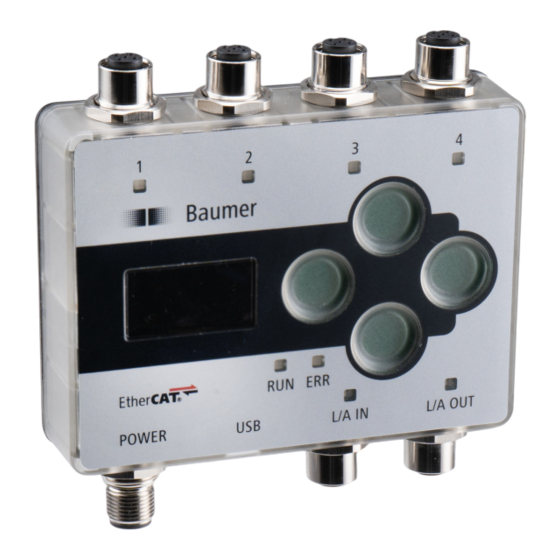
Page 10: Controller Box: Control And Display Elements
Process data watchdog timeout/ EtherCAT watchdog timeout No errors Sensor 1-4 GREEN continuous Sensor in operation RED continuous Alarm flashing RED Connection to sensor expected, but not present. No sensor connection. Description of functions and interfaces OE60, OE60C | V1... -
Page 11: Commissioning
When attached to the T-adaptor, the sensor heads can be integrated into the RS485 network. Both ports of the T-adapter can be connected to emitter and receiver. Alignment will not change at all. Ill. 1: Sensor heads OE60 with T-adapter Check proper alignment of transmitter and receiver with function alignment... -
Page 12: Measured Value Readout Via Modbus Rtu
For more detailed information on the following please refer to chapter Annex [} 50]. There are two options for measured value readout (see table below). Measured value and additional information via address 105. Measured value only via address 114. Description of functions and interfaces OE60, OE60C | V1... - Page 13 Modbus access - Input Register: Measurement value Read adress 114 - length: 2 registers Number of Adresse Access registers Data type Description 114-115 Read int_32 Measurement value: Measured edge position in nm V1 | OE60, OE60C Description of functions and interfaces...
-
Page 14: Connecting The Controller Box
T-adapter. The T-adapter enables direct connection to the controller box. Both connectors of the T-adapter can be connected to both emitter and receiver. Alignment will not change at all. Ill. 2: Sensor heads OE60 with controller box OE60C 4.2.1 Controller box menu navigation Both display and buttons act as controller user interface. - Page 15 Digital Out 2 Switch Point 2 Hysteresis Polarity Factory Reset Factory Reset Reset Confirm Reset command CAUTION Entries in italics are only visible with the selected settings or correspondingly connected sen- sors. V1 | OE60, OE60C Description of functions and interfaces...
- Page 16 . >ALL Sensors Select the required setting using the buttons Zero Position >0.3 mm . >ALL Sensors Confirm with Zero Position 0.3 mm The setting in Zero Position changes to the new value. Description of functions and interfaces OE60, OE60C | V1...
-
Page 17: Readout Measured Value Via Ethercat
Measurement value for sensor 1. Sensor 2 Measurement Value 1A02 Measurement value for sensor 2. Sensor 3 Measurement Value 1A03 Measurement value for sensor 3. Sensor 4 Measurement Value 1A04 Measurement value for sensor 4. V1 | OE60, OE60C Description of functions and interfaces... -
Page 18: Alignment Assistant
Any misalignment may lead to measurement errors. Once alignment verification has been com- pleted, disable the alignment assistant. With disabled alignment assistant, the LED indicator changes significance as described in chap- Operating and display elements of the sensor heads [} 9]. Description of functions and interfaces OE60, OE60C | V1... - Page 19 Modbus access - Input Register: Status Mounting assistant Read adress 121 - length: 1 registers Number of Address Access registers Data type Description Read int_8 Status Mountain assistant: 0 = Inactive 1 = Active *Unused Byte (uint_8)* V1 | OE60, OE60C Description of functions and interfaces...
- Page 20 TRUE = Activate 80X13 10 Activate/deaktivate mounting assistant for sensor 3. FALSE = Deactivate TRUE = Activate 80X14 10 Activate/deaktivate mounting assistant for sensor 4. FALSE = Deactivate TRUE = Activate Description of functions and interfaces OE60, OE60C | V1...
-
Page 21: Interfaces
In general, all registers enable write and read. Reading a register with write access only will re- ply 0xFFFF. For more detailed information on the following please refer to chapter Annex [} 50]. Discrete Inputs: FC 02 Number of Address registers Command Description Alarm Measured value OK/NOK V1 | OE60, OE60C Description of functions and interfaces... - Page 22 Coils: FC 01/05 Address Command Description Teach zero position Teaching the zero point position Laser OFF Laser ON/OFF Axis inversion Invert measuring axis Factory reset Restore default Mounting assistant Enable/disable alignment assistant Description of functions and interfaces OE60, OE60C | V1...
-
Page 23: Communication Parameters
Possible values are: 0 = 19200 1 = 38400 2 = 57600 3 = 115200 4 = 128000 5 = 256000 6 = 2000000 *Unused byte (uint8)* V1 | OE60, OE60C Description of functions and interfaces... -
Page 24: Ethercat
ESI file (EtherCat Subdevice information). The ESI file is available on the OE60C product detail page at the website "Downloads" section. INFO The ESI file is available for download at the Baumer website on the sensor page (download section). See also chapter Annex [} 50]... -
Page 25: Operating Functions
The median value is the mea- sured value located right “in the center” if the measured values are sorted by size. Time Ill. 4: Moving Median filter Raw data Data after filtering with Moving Median V1 | OE60, OE60C Description of functions and interfaces... - Page 26 Moving Average and Moving Median filters. You can specify the length of the Moving Average and Moving Median filters after selecting the Custom filter. Moving Median filter: 1 - 18 values Moving Average filter: 1 - 128 values Description of functions and interfaces OE60, OE60C | V1...
- Page 27 Number of Adresse Access registers Data type Description Read/Write uint_8 Select Precision filter preset 0 = Standard 1 = High 2 = Very High 3 = Custom Reserved (uint_8): Unused byte V1 | OE60, OE60C Description of functions and interfaces...
- Page 28 Length of the moving median filter kernel. Can only be written with "Precision" is set to man- ual. * The X in the index stands for the sensor number. As example: for sensor 1, the index is 8011. Description of functions and interfaces OE60, OE60C | V1...
-
Page 29: Laser On/Off
Confirm with Result: ü The lasers of the selected sensors are on or off according to the setting made. For more detailed information on the following please refer to chapter Annex [} 50]. V1 | OE60, OE60C Description of functions and interfaces... - Page 30 Switch off the laser for the individual sensor pairs. Sensor 3 Laser Off 2001 Switch off the laser for the individual sensor pairs. Sensor 4 Laser Off 2001 Switch off the laser for the individual sensor pairs. Description of functions and interfaces OE60, OE60C | V1...
-
Page 31: Measuring Axis Configuration
The sign > comes in the first digit of the current setting. g) Select the required setting using the buttons h) Confirm with Result: ü The selected sensors will adopt the measuring axis setting. V1 | OE60, OE60C Description of functions and interfaces... - Page 32 Axis inversion for sensor 1 - 4. 8021 The axis inversion can be set to: 8031 0 = min-to-max 8041 1 = max-to-min Also see about this 2 Controller box menu navigation [} 14] Description of functions and interfaces OE60, OE60C | V1...
-
Page 33: Switching Points
▪ Align the object until it is in the required edge position. Window mode SP1/SP2 SP1/SP2 Ill. 8: Sensor in switching mode Window mode Purpose/application (example): ▪ Quality control: Checking the object width within a tolerance window. V1 | OE60, OE60C Description of functions and interfaces... - Page 34 This applies to all sensor head pairs S1-S4: None Position S1 Alarm S1 Contamin. S1 Mode F800 Mode for switch points. Switch Point 1 F800 Switch point 1. Switch Point 2 F800 Switch point 2. Description of functions and interfaces OE60, OE60C | V1...
- Page 35 This applies to all sensor head pairs S1-S4: None Position S1 Alarm S1 Contamin. S1 Mode F800 Mode for switch points. Switch Point 1 F800 Switch point 1. Switch Point 2 F800 Switch point 2. V1 | OE60, OE60C Description of functions and interfaces...
-
Page 36: Hysteresis
The function prevents unwanted switching operations at the switching output. The parameter- ized value of the hysteresis is the difference in distance between the points at which the switch- ing output is activated and deactivated. Baumer recommends always setting the hysteresis not equal to 0. - Page 37 For more detailed information on the following please refer to chapter Annex [} 50]. EtherCAT access: Hysteresis Name Index Subindex Description Hysteresis F800 Hysteresis for switching output 1. Hysteresis F801 Hysteresis for switching output 2. V1 | OE60, OE60C Description of functions and interfaces...
-
Page 38: Polarity
Point mode: switching output is enabled when exceeding the defined measured value SP1. Window mode: The switching output is activated as soon as the measured value is outside the window of SP1 and SP2. Description of functions and interfaces OE60, OE60C | V1... - Page 39 For more detailed information on the following please refer to chapter Annex [} 50]. EtherCAT access: Polarity Name Index Subindex Description Polarity F800 Polarity for switching output 1. Polarity F801 Polarity for switching output 2. V1 | OE60, OE60C Description of functions and interfaces...
-
Page 40: Zero Position
Physical edge position within the measuring range: -5 mm Set zero position: -3 mm Output measured value: -2 mm For detailed information on menu structure and display please see chapter Controller box menu navigation [} 14]. Description of functions and interfaces OE60, OE60C | V1... - Page 41 The sign > comes in the first digit of the current setting. g) Select the required numerical value with buttons h) Confirm with Result: ü Zero point has been set to the new value. V1 | OE60, OE60C Description of functions and interfaces...
- Page 42 Teach the zero position. Zero position 80X1* 06 Set value for zero position. * The X in the index stands for the sensor number. As example: for sensor 1, the index is 8011. Description of functions and interfaces OE60, OE60C | V1...
-
Page 43: Factory Settings
This function will restore the default sensor values and parameterization. Default will be re- stored in the entire user settings. Restore default of sensor and controller box is individually. Overview on default settings OE60 (sensor) Adjustable parameters Factory setting in the sensor... - Page 44 The X in the index stands for the sensor num- ber. As example: for sensor 1, the index is 8011. Restore all default parame- 1011 Reset controller box (incl. switching outputs ters that are only available on the box). Description of functions and interfaces OE60, OE60C | V1...
-
Page 45: Behavior In The Event Of Incorrect Measured Values
- sensor holding time of the min. measured value. max - sensor holding time of the max. measured value. last valid - sensor holding time of the last valid measured value. V1 | OE60, OE60C Description of functions and interfaces... - Page 46 Dropout value (uint8): Invalid values are replaced with this value: ▪ 0: min ▪ 1: max ▪ 2: last valid *Unused byte (uint8)* Description of functions and interfaces OE60, OE60C | V1...
- Page 47 Invalid values are replaced with this value: 0: min 1: max 2: last valid * The X in the index stands for the sensor number. As example: for sensor 1, the index is 8011. V1 | OE60, OE60C Description of functions and interfaces...
-
Page 48: Diagnostic Functions
Identify Object 1018 Vendor ID 1018 Unique, vendor-specific identifier of the indi- vidual device. Product Code 1018 Unique, vendor-specific product code. Revision Number 1018 Description of functions and interfaces OE60, OE60C | V1... - Page 49 Baumer Diagnostic functions Name Index Subindex Description Serial Number 1018 Timestamp Object 10F8 V1 | OE60, OE60C Description of functions and interfaces...
-
Page 50: Annex
The sensor will perform a factory reset, if 1 gets written to the coil. mounting_assis- The mounting assistant will be disabled (when on, a yel- tant_enabled low LED indicates incorrect allignment), if 0 gets written to this coil. Description of functions and interfaces OE60, OE60C | V1... -
Page 51: Input Registers
* Data volume exceeds 16 bits (corresponding to a register); reading only by function call. Se- lect the corresponding registers by function call via Function Code 03 or Function Code 04. No access to individual registers. V1 | OE60, OE60C Description of functions and interfaces... -
Page 52: Holding Register
(uint8): The modbus slave address of the sensor. dress The sensor will answer with its old address and afterwards act only on messages to the new ad- dress. padding0 (uint8): Unused byte Description of functions and interfaces OE60, OE60C | V1... - Page 53 * Data volume exceeds 16 bits (corresponding to a register); reading only by function call. Se- lect the corresponding registers by function call via Function Code 03 or Function Code 04. No access to individual registers. Sensor access denied. V1 | OE60, OE60C Description of functions and interfaces...
-
Page 54: Ethercat
EtherCat 8.2.1 Standard objects Access Index Subindex Name Data type rights Value range Description 1000 Device Type UDINT Vendor-specific product or type identification, e. g. item number or model number. 1008 Device Name STRING(5) ASCII Complete product name. 1009 Hardware Version STRING(27) ASCII Unique, vendor-specific identifier of the hardware revision of the... -
Page 55: Cyclical Output Data Rxpdo
8.2.2 Cyclical output data RxPDO Index Subindex Name Data type Access rights Value range Description 17ff Device Control UDINT Control Value: Alarm if the box would be defective. 0 = OK 1 = Error, box must be checked 1601 Sensor 1 Values Number of entries USINT Switch off the laser for the individual sensor pairs. -
Page 56: Cyclical Input Data Txpdo
8.2.3 Cyclical input data TxPDO Index Subindex Name Data type Access rights Value range Description 1A00 Device TxPDO Number of entries USINT Control Value UDINT 0...42949672 1A01 Sensor 1 TxPDO Number of entries USINT Sensor 1 Status UDINT 0...42949672 Status for sensor 1 Sensor 1 Measure- DINT -2147483648... - Page 57 Index Subindex Name Data type Access rights Value range Description 1A03 Sensor 3 TxPDO Number of entries USINT Sensor 3 Status UDINT 0...42949672 Status for sensor 3 Sensor 3 Measure- DINT -2147483648 Measurement value for sensor 3 ment Value 2147483647 Sensor 3 Contamina- UDINT 0...42949672...
-
Page 58: Acyclic Output Data
8.2.4 Acyclic output data Index Subindex Name Data type Access rights Value range Description 2000 Device OUTPUT Number of entries USINT Control Value UDINT 0...42949672 2001 Sensor 1 OUTPUT Number of entries USINT Sensor 1 Laser Off UDINT 0...42949672 2002 Sensor 2 OUTPUT Number of entries USINT... -
Page 59: Acyclic Input Data
8.2.5 Acyclic input data Index Subindex Name Data type Access rights Value range Description 3000 Device INPUT Number of entries USINT Control Value UDINT 0...42949672 3001 Sensor 1 INPUT Number of entries USINT Sensor 1 Status UDINT 0...42949672 Status for sensor 1: 0 = OK 1 = NOK, no valid measured value can be recorded, e.g. - Page 60 Index Subindex Name Data type Access rights Value range Description 3003 Sensor 3 INPUT Number of entries USINT Sensor 3 Status UDINT 0...42949672 Status for sensor 3: 0 = OK 1 = NOK, no valid measured value can be recorded, e.g. no measurement object in the measurement range Sensor 3 Measure- DINT...
-
Page 61: Acyclic Parameterization Options
8.2.6 Acyclic parameterization options Index Subindex Name Data type Access rights Value range Description 9000 Device Info Number of entries USINT Product ID STRING(9) Product Type STRING(65) R Serial Number STRING(20) R Firmware Version STRING(30) R 8010 Sensor 1 Device Info Number of entries USINT Product ID... - Page 62 Index Subindex Name Data type Access rights Value range Description 8011 Sensor 1 Configuration Number of entries USINT Teach Zero Position BOOL Laser Off BOOL Axis Inversion BOOL Factory Reset BOOL Reserve UINT Zero Position DINT Invalid Value Handling BOOL Whether the invalid value handling is being used or not.
- Page 63 Index Subindex Name Data type Access rights Value range Description 8020 Sensor 2 Device Info Number of entries USINT Product ID STRING(9) Product Type STRING(65) R Serial Number STRING(20) R Firmware Version STRING(30) R 8021 Sensor 2 Configuration Number of entries USINT Teach Zero Position BOOL...
- Page 64 Index Subindex Name Data type Access rights Value range Description 8030 Sensor 3 Device Info Number of entries USINT Product ID STRING(9) Product Type STRING(65) R Serial Number STRING(20) R Firmware Version STRING(30) R 8031 Sensor 3 Configuration Number of entries USINT Teach Zero Position BOOL...
- Page 65 Index Subindex Name Data type Access rights Value range Description 8040 Sensor 4 Device Info Number of entries USINT Product ID STRING(9) Product Type STRING(65) R Serial Number STRING(20) R Firmware Version STRING(30) R 8041 Sensor 4 Configuration Number of entries USINT Teach Zero Position BOOL...
-
Page 66: Controller Box -Specific Parameters
8.2.7 Controller box -specific parameters Index Subindex Name Data type Access rights Value range Description F000 Modular Device Profile Describes the module structure. Number of entries USINT Index distance UINT Maximum number of UINT modules F800 Switching Output 1 Parameterization of the switching output 1. Number of entries USINT Source... - Page 67 Index Subindex Name Data type Access rights Value range Description Switch Point 1 DINT Switch point 1. Switch Point 2 DINT Switch point 2. Hysteresis DINT Hysteresis for switching output 2. Polarity EN32 Polarity for switching output 2. F802 Touch lock BOOL The control panel (buttons) can be locked to prevent the parame- terization of the sensors via the control panel.
- Page 68 Baumer Electric AG Hummelstrasse 17 CH − 8501 Frauenfeld www.baumer.com...
Need help?
Do you have a question about the OE60 and is the answer not in the manual?
Questions and answers