Table of Contents
Advertisement
Quick Links
Advertisement
Chapters
Table of Contents

Related Manuals for Baumer OM60 Modbus


Summary of Contents for Baumer OM60 Modbus
- Page 1 Operating Manual OM60 Modbus EN-US Laser distance sensor...
-
Page 2: Table Of Contents
8 Commissioning ............................21 Set up RS485 interface with Modbus RTU ..................21 9 Operating functions ............................ 23 Measured value and additional information ..................23 Filter ..............................24 Trigger mode (sampling mode) ......................28 Operating Manual OM60 Modbus | V1... - Page 3 10.4 Operating time............................. 51 10.5 Device temperature..........................52 10.6 Identification ............................52 11 Maintenance..............................54 11.1 Cleaning the sensor ..........................54 12 Troubleshooting ............................55 12.1 Return and repair ..........................55 12.2 Accessories............................55 V1 | OM60 Modbus Operating Manual...
-
Page 4: About This Document
In addition, the local occupational health and safety regulations and general safety regulations apply. The illustrations in this manual are examples only. Deviations are at the discretion of Baumer at all times. Warnings in this manual Warnings draw attention to potential personal injury or material damage. -
Page 5: Labels In This Manual
In addition, you can find the following information, among other things, in digital format at www.baumer.com: Instruction manual Data sheet 3D CAD drawing Quickstart Dimensional drawing Connection diagram & pin assignment Certificates (EU conformity declaration, etc.) V1 | OM60 Modbus Operating Manual... -
Page 6: Safety
Use shielded cables to prevent electro-magnetic interference. If the customer assembles plug connections on shielded cables, then EMC-version plug connections should be used and the cable shield must be connected to the plug housing across a large sur- face area. Operating Manual OM60 Modbus | V1... -
Page 7: Laser
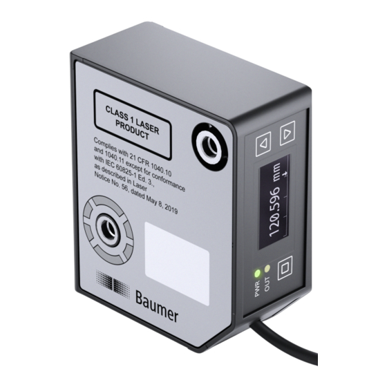
Complies with 21 CFR 1040.10 and 1040.11 except for conformance with IEC 60825-1 Ed. 3., as described in Laser Notice No. 56, dated May 8, 2019 Products with the following type code fall under laser class 1: OM60-xxxxx.HH.xxx V1 | OM60 Modbus Operating Manual... -
Page 8: Description
RS485 interface with Modbus RTU protocol The following options are available to you for parameterizing the sensor: RS485 interface with Modbus RTU protocol Teach button on the sensor Operating Manual OM60 Modbus | V1... -
Page 9: Measurement Field
The following values depend on the zero position: ▪ Output measured values ▪ Switching points Capable of parameterization via: ▪ Modbus RTU ▪ Teach button V1 | OM60 Modbus Operating Manual... -
Page 10: Operating And Display Elements
57600 Baud Baudrate 115200 Baud 3.4.2.1 Operation Display Activate the display by briefly pressing any button Display reset after 2 minutes: display goes back to start screen. Display will be automatically inactive after 5 minutes Operating Manual OM60 Modbus | V1... -
Page 11: Dimensional Drawing
Call up submenu Confirm: save new value and exit value set- tings Exit submenu Back: Do not save new value and exit value press and settings hold >1 s Dimensional drawing 27.2 ca. 45 V1 | OM60 Modbus Operating Manual... -
Page 12: Reflection Area
Ambient light in the reflection may have an effect on the measured values. For this reason, where possible prevent ambient light from entering the reflection area (marked in gray in the diagram). Operating Manual OM60 Modbus | V1... -
Page 13: Transport And Storage
Keep away from the sun. Avoid mechanical agitation. Storage temperature: -10 ... +60 °C. Ambient humidity:. 20 ... 85 % When storing for longer than 3 months, regularly check the general state of all parts and the packaging. V1 | OM60 Modbus Operating Manual... -
Page 14: Installation
Installation Baumer Installation INFO You can find the suitable installation accessories on the Baumer website. Go to www.baumer.com for this. Then enter the item number of the sensor in the search field of the website. For glossy objects: incline the sensor by 6 to 10° to the side so that any surface-reflecting light will not be detected by the sensor's receiver. - Page 15 Prevent the detection ranges of the receivers from overlapping. Only the sensor’s own laser spot may be in the detection range of the receiver. ü û Mounting for round measurement objects: Align the sensor on the same axis as the measurement object to prevent reflections. V1 | OM60 Modbus Operating Manual...
-
Page 16: Electrical Installation
4 – Black Rx/Tx+ GY (5) control input 5 – Grey Connecting the sensor to electricity Instruction: a) Ensure that the system is disconnected from power. b) Connect the sensor according to the pin assignment. Operating Manual OM60 Modbus | V1... -
Page 17: Interfaces
Measurement range lower Set measuring range limit (near) limit Measurement range upper Set measuring range limit (far) limit Meas range to max Maximize measurement range Setpoint 1.1 Switchpoint 1 (SP1) of switching output 1 V1 | OM60 Modbus Operating Manual... - Page 18 LED function parameterization Input register: function ID 04 Number of Address registers Command Description Vendor name Manufacturer name Vendor text Manufacturer's note Product name Product name Product ID Item number Product text Product text Operating Manual OM60 Modbus | V1...
-
Page 19: Communication Parameters
Data type Description 1100 Read/write uint8 The slave address of the sensor. The sensor will answer with its old address and afterwards act only on messages to the new address. *Unused byte (uint8)* V1 | OM60 Modbus Operating Manual... - Page 20 Afterwards communication is only possible using the new baudrate. Possible values are: 1 = 38400 2 = 57600 3 = 115200 *Unused byte (uint8)* Operating Manual OM60 Modbus | V1...
-
Page 21: Commissioning
Reply delay [µs] 209 - 210 uint32_t Time stamp [s] 211 - 212 uint32_t Time stamp [µs] The following data (hexadecimal) is read out for the distance value: 202 = 7C37 203 = 428B V1 | OM60 Modbus Operating Manual... - Page 22 202. The more significant bits are lo- cated at the larger address, in this case 203. The distance value must therefore be evaluated as 42 8B 7C 37. This results in a distance of 69.743 mm. Operating Manual OM60 Modbus | V1...
-
Page 23: Operating Functions
The distance value in address 202 and 203 can also be read individually. For this, read out reg- ister 202 with register number 2. A single readout of the distance can reduce the transmission time. V1 | OM60 Modbus Operating Manual... -
Page 24: Filter
The median value is the mea- sured value located right “in the center” if the measured values are sorted by size. Time Ill. 3: Filter Moving Median Raw data Data after filtering with Moving Median Operating Manual OM60 Modbus | V1... -
Page 25: Ill. 4 Moving Average Filter
Moving Average and Moving Median filters. You can specify the length of the Moving Average and Moving Median filters after selecting the Custom filter. Moving Median filter: 1 - 21 values Moving Average filter: 1 - 512 values V1 | OM60 Modbus Operating Manual... - Page 26 Number of Address Access registers Data type Description Read/write uint16 This setting is only enabled if se- lected value Custom is at Precision Filter. Custom median filter length (uint16): min. 1 - max. 21 values Operating Manual OM60 Modbus | V1...
- Page 27 Number of Address Access registers Data type Description Read/write uint16 This setting is only enabled if se- lected value Custom is at Precision Filter. Custom average filter length (uint16): min. 1 - max. 512 val- V1 | OM60 Modbus Operating Manual...
-
Page 28: Trigger Mode (Sampling Mode)
Having selected trigger mode External Trigger (single measurement), the measuring operation must be started via Control Input. Every falling edge at Control Input triggers another measure- ment. The existing sensor status remains until the first falling edge. Further information: Control Input Settings [} 32] Operating Manual OM60 Modbus | V1... - Page 29 Select the trigger mode: 0: Free Running 2: Interval Address 402 – Fix Time Trigger Intervall: Number of Address Access registers Data type Description 402 - 403 Read/write uint32_t Numerical time interval in Interval mode [µs] V1 | OM60 Modbus Operating Manual...
-
Page 30: Zero Position
ð The object is in teaching position within the measuring range. a) Open menu with b) With buttons you navigate to menu item Zero position. c) Confirm with d) With buttons you navigate to function Teach. Operating Manual OM60 Modbus | V1... - Page 31 180 - 181 Read/write int32_t Numerical zero position [μm] Address 185 – Teach Zero Position: Number of Address Access registers Data type Description Write Teach zero position: Call up the function by writing any number. V1 | OM60 Modbus Operating Manual...
-
Page 32: Control Input Settings
With buttons you select the desired settings at(laser on/off zero position). g) Confirm with Result: ü Control input is set to the selected function. Trigger follows the description in the above ta- ble. Operating Manual OM60 Modbus | V1... - Page 33 Modbus RTU command - Holding Register: Control input setting Number of Address Access registers Data type Description Read/write uint_16 Defines the function of control input on line 5. 1: Teach Input (Zero Position Teach) 3: Laser On/Off (Sync Input) V1 | OM60 Modbus Operating Manual...
-
Page 34: Measurement Range
Maximum limit of measuring range [mm] Address 220 – Meas Range to MAX: Number of Address Access registers Data type Description Read Maximize measurement range: Call up the function by writing any num- ber. Operating Manual OM60 Modbus | V1... -
Page 35: Switching Points
▪ Point mode: SP1 ▪ Window mode: SP1 and SP2 INFO When using Baumer Sensor Suite for configuration, you may have to change the add-on view to access the required settings. To change view, click on next to Parametrization. Next select the view from the drop-down list. - Page 36 Address 304 - Switch mode 2: Number of Address Access registers Data type Description 314 - 315 Read/write int32_t Select switching mode of switching output 2: 0: Disabled 1: Point 2: Window 3: Two-point Operating Manual OM60 Modbus | V1...
-
Page 37: Polarity
Modbus RTU command - Holding register: Polarity switching point 1 Address 308 - Polarity : Number of Address Access registers Data type Description Read/write uint16 Polarity of the switching output: 0 = Active low 1 = Active high V1 | OM60 Modbus Operating Manual... -
Page 38: Hysteresis
Function hysteresis prevents unwanted switching operations by the switching output. The pa- rameterized value of the hysteresis is the difference in distance between the points at which the switching output is activated and deactivated. Baumer recommends always setting the hystere- sis not equal to 0. -
Page 39: Ill. 12 Negative Hysteresis
This hysteresis behavior corresponds to IO-Link Smart Sensor Profile DMSS with extension "Object detection". Point mode (switching output behavior) Positive hysteresis: Hysteresis Switching point P1 High Active low level Level Ill. 13: Behavior of the switching output in point mode (positive hysteresis) V1 | OM60 Modbus Operating Manual... -
Page 40: Ill. 14 Behavior Of The Switching Output In Point Mode (Negative Hysteresis)
Ill. 15: Behavior of the switching output in window mode (positive hysteresis) Negative hysteresis: Switching point P1 Hysteresis Window Hysteresis Switching point P2 High Level Active high level Ill. 16: Behavior of the switching output in window mode (negative hysteresis) Operating Manual OM60 Modbus | V1... -
Page 41: Teaching
Current setting comes with symbol >. f) Confirm teaching operation with button ü The distance towards the object in the measuring range is measured and saved as new zero point. Result: ü Switchpoint teaching completed. V1 | OM60 Modbus Operating Manual... - Page 42 Select with f) Enable editing with ü Current setting comes with symbol >. g) Use buttons to select the required value. h) Confirm with Result: ü Zero point has been set to the new value. Operating Manual OM60 Modbus | V1...
-
Page 43: Behavior In The Event Of Incorrect Measured Values
Interpretation: After expiration of the time period, the placeholder for an invalid value is out- put at the digital output. Digital output Hold Time Signal quality Ill. 18: Processing of invalid measured values – example 2 V1 | OM60 Modbus Operating Manual... - Page 44 Modbus RTU command – holding register: processing of invalid measured values Address 800 – Dropout Timeout: Number of Address Access registers Data type Description Read/write uint32 Interval for suppressing invalid mea- sured values [ms] Operating Manual OM60 Modbus | V1...
-
Page 45: Laser On/Off
IO-Link access - Laser on/off Modbus RTU command – holding register: laser Address 410 – Laser On/Off: Number of Address Access registers Data type Description Read/write uint16_t Status of the laser: 0 = off 1 = on V1 | OM60 Modbus Operating Manual... -
Page 46: Factory Settings
Logic Active High Mode Single Point Hysteresis depending on MR Input/Output Settings LED function SSC1 - Alarm Control Input Laser On/Off (Sync In- put) * = value according to measuring range (see data sheet) Operating Manual OM60 Modbus | V1... -
Page 47: Function Of The Led
Modbus RTU command – holding register: LED Function Address 1102 – LED Function: Number of Address Access registers Data type Description 1102 Read/write uint16_t Determine the function of the LED: 100 = switching output 101 = alarm output V1 | OM60 Modbus Operating Manual... -
Page 48: Diagnostic Functions
Display shows the current measuring rate in [Hz]. Modbus RTU command - Input register: measuring frequency Address 204-205 - measuring frequency: Number of Address Access registers Data type Description 204-205 Read/write uint16_t Measuring frequency in [Hz] Operating Manual OM60 Modbus | V1... -
Page 49: Reply Delay
Filter settings do not affect the reply delay. Modbus RTU command - input register: response delay Address 207-208 - response delay: Number of Address Access registers Data type Description 207-208 Read/write uint16_t Response delay in [us]. V1 | OM60 Modbus Operating Manual... -
Page 50: Exposure Reserve
Display shows the current exposure reserve in [%]. Modbus RTU command - input register: exposure reserve Address 206- Exposure reserve: Number of Address Access registers Data type Description Read/write uint16_t Exposure reserve in [%] Operating Manual OM60 Modbus | V1... -
Page 51: Operating Time
Number of Address Access registers Data type Description Read uint32_t Operating time since sensor power Address 305 - Lifetime operating time Number of Address Access registers Data type Description Read uint32_t Total operating time V1 | OM60 Modbus Operating Manual... -
Page 52: Device Temperature
Modbus RTU command – input register: device information Address 0 – Vendor Name: Number of Address Access registers Data type Description Read STRING[] Manufacturer Address 16 – Vendor Text: Number of Address Access registers Data type Description Read STRING[] Manufacturer’s note Operating Manual OM60 Modbus | V1... - Page 53 Address 105 - Hardware revision: Number of Address Access registers Data type Description Read STRING[] Sensor hardware version Address 110 – Firmware Revision: Number of Address Access registers Data type Description Read STRING[] Sensor firmware version V1 | OM60 Modbus Operating Manual...
-
Page 54: Maintenance
Do not use scouring agents, solvents, or other aggressive cleaning agents. c) Do not use jets of liquid for cleaning, for example, a high-pressure cleaner. d) Do not scrape off contamination with sharp-edged items. Interior cleaning No interior cleaning of the sensor is required. Operating Manual OM60 Modbus | V1... -
Page 55: Troubleshooting
(e.g. by using a cover). sults in interference peaks on the receiver. 12.1 Return and repair In case of complaints, please contact the relevant sales company. 12.2 Accessories You can find accessories at the website at: www.baumer.com V1 | OM60 Modbus Operating Manual... -
Page 56: List Of Illustrations
Behavior of the switching output in window mode (negative hysteresis) ..........40 Ill. 17 Processing of invalid measured values – example 1 ................43 Ill. 18 Processing of invalid measured values – example 2 ................43 Ill. 19 Reply delay ............................49 Operating Manual OM60 Modbus | V1... - Page 60 Baumer Electric AG Hummelstrasse 17 CH − 8501 Frauenfeld www.baumer.com...
Need help?
Do you have a question about the OM60 Modbus and is the answer not in the manual?
Questions and answers