Table of Contents
Advertisement
Quick Links
Advertisement
Table of Contents

Related Manuals for Argo ODIN PLUS


Summary of Contents for Argo ODIN PLUS
-
Page 2: Table Of Contents
Index 1. Safety Considerations..............1 2. Product Picture and Drawing............3 2-1. Product Pictures..............3 2-2. Accessories................3 3. Function Operation..............4 3-1. Operation Range (cooling and heating).........4 3-2. Remote Controller Operation & Function........4 3-3. Function Instruction ...............5 4.Trouble Shooting.................6 4-1.Trouble Shooting ..............6 4-2. Error Code Table..............8 5. -
Page 3: Safety Considerations
1. Safety Considerations IMPORTANT! Please Read Before Starting This air conditioning system meets strict safety and operating standards. As the installer or service person, it is an important part of your job to install or service the system, so it operates safely and efficiently. For safe installation and trouble free operation, you must: ·Carefully read this instruction booklet before beginning. - Page 4 If Necessary, Get Help These instructions are all you need for most installation sites and maintenance conditions. If you require help for a special problem, contact our sales/service outlet or your certified dealer for additional instructions. In Case of Improper Installation The manufacturer shall in no way be responsible for improper installation or maintenance service,Including failure to follow the instructions in this document.
-
Page 5: Product Picture And Drawing
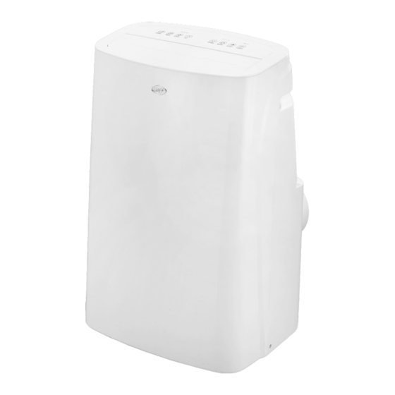
2. Product& Accessories Picture 2-1. Product and Accessories Pictures Item Front panel review Rear panel Top review review ODIN PLUS 2-2.Accessories: Pictures Part Name Sizes/cm Max. Thickness:φ155.5mm Connector to the unit ABS/427C/44g W:237*D:137mm Connector to the slide bar Outer diameter φ155mm thickness φ151±0.3mm... -
Page 6: Function Operation
31℃ Setting temp Maxi. Cooling&Heat 16℃ Setting temp Mini. pump 3-2. Remote Controller Operation & Function operation instructions of remote control 1) The remote control Panel is as follows: Icon Function Function description Power Press the key to turn on or turn off the machine. Press “+”... -
Page 7: Function Instruction
Press the key to select high, medium and low wind speed output circularly. Temperature Press the key to switch between Celsius and Fahrenheit. 3-3. Function Instruction 1.Control panel operation instructions Icon Function Function description The SWING function only can work after turn on the unit, Swing but you can turned on or off. -
Page 8: Trouble Shooting
Under timer mode, press this key can be adjusted downward the time. Under cooling and heating mode, press this key can be adjusted downward the temperature. Down Press this button to decrease the temperature setting or set down the timer to the required timer setting. This function is not available under FAN mode and DEHUMIDIFYING mode. - Page 9 1.Let machine on flat place and 1.Machine is not placed well Abnormal noise stand upright 2.Filters is blocked 2. Clean the filters Heat air doesn’t go 1.Environmental temperature is 1.Make setting temperature is out immediately higher than setting temperature higher than environmental under heating 2.Heat air will blow out three temperature...
-
Page 10: Error Code Table
1.The compressor capacity damaged 1.Replace the compressor capacity 2.The compressor stops for 3 Compressor nor 2.Wait for three minutes and minutes and the protection work restart the machine. function is activated When the 3.Replace the compressor. machine ran for a long time 3.The compressor damaged 4-2. - Page 11 Temperature Sensor resistance value table:...
-
Page 12: Disassemble Instructions
5.Disassemble instructions 5-1. Disassemble Instruction Gather the required tools and parts before starting installation.Read and follow the instructions provided with any tools listed here. Tools needed ·Plillips screwdriver ·Scissors ·Cordless drill 5-2. Electric Wiring Diagram This wiring diagram is applicable for whole function unit, included cooling function, heat pump, WIFI etc. -
Page 13: Refrigerant Flow System
5-3.Refrigerant Flow System 5.4 Disassemble details Check before Disassemble that you have Switch off power. (1) Whole unit drawing... - Page 14 (2) Disassemble the upper filter housing and upper filter: Use your hand to buckle the two latches on the top of the filter housing and pull it out, and then take out the filter housing. Filter housing Filter (3)Disassemble the rear panel. ·Use a screwdriver to remove the two screws on the left and right handles Firstly.
- Page 15 Front panel (5)Remove the top panel assembly ·Use a screwdriver to remove the two screws behind the top panel assembly. ·Pull out the connecting terminals, buckle both sides of the top cover with your hands, and take out the top panel assembly after the top panel assembly is separated from the body. Front panel Top panel (6)Split top cover and control panel...
- Page 16 ·Loosen the three screws on the back of the display board, take out the display board and pull out the connecting terminal. Louver Top panel Cover of display board Display board Box of display board (7)Disassemble the electric control box ·Remove the screw fixing the cover of the electrical box and remove the cover of the electrical box.
- Page 17 (8)Split air supplier duct components ·Remove the two screws connecting the air duct assembly to the top of the evaporator and the two screws connecting the middle partition, and move them out horizontally Upper air duct · Remove the WIFI components, two screws fixed on the , and five screws on the volute. ·...
- Page 18 ·Remove the screw on the left and right sides of the middle partition and the evaporator, and then remove the two fixing screws connecting the middle partition and the exhaust air duct assembly. · Remove the one screw connecting the middle partition behind the air conditioner and the condenser.
- Page 19 ·Remove the 2 screws fixing the protective net and the exhaust air duct assembly, and remove the protective net. ·Remove the 5 screws connecting the upper and lower volutes of the air duct assembly, and remove the lower volute of the exhaust air. Protective net lower volutes of the air duct...
- Page 20 Evaporator The support frame Condenser Compressor Bottom base (12)Disassemble the bottom components ·Remove the 2 screws of the magnetic ring switch assembly ·Remove the screw on the main bracket ·Remove the 4 screws connecting the water dispenser component and the bottom ·...
Need help?
Do you have a question about the ODIN PLUS and is the answer not in the manual?
Questions and answers