Table of Contents
Advertisement
Quick Links
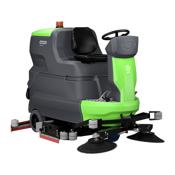
CT231
(IT) MANUALE ISTRUZIONI PER L'USO
(EN) OPERATOR'S MANUAL
(FR) MANUEL D'INSTRUCTIONS
(DE) BEDIENUNGSANLEITUNG
(ES) MANUAL DE INSTRUCCIONES
(NO) BRUKERHÅNDBOK
(NL) GEBRUIKERSHANDLEIDING
(PT) MANUAL DE UTILIZAÇÃO
(SE) INSTRUKTIONSBOK
(RU) РУКОВОДСТВО ОПЕРАТОРА
(BG) РЪКОВОДСТВО ЗА ЕКСПЛОАТАЦИЯ
(DK) BETJENINGSMANUAL
Consultare attentamente questo manuale prima di procedere a qualsiasi intervento sulla macchina
Read this manual carefully before carrying out any work on the machine
Lire attentivement ce manuel avant toute intervention sur la machine
Vorliegendes Handbuch vor jedem Eingriff an der Maschine aufmerksam durchlesen
Consulte detenidamente este manual antes de llevar a cabo cualquier trabajo en la máquina
Konsulter denne håndboken nøye før du går i gang med noen som helst type inngrep på maskinen
Raadpleeg deze handleiding aandachtig alvorens met enige werkzaamheid aan de machine te beginnen
Consulte atentamente este manual antes de efectuar qualquer intervenção na máquina
Läs noggrant igenom denna handbok innan du utför något som helst ingrepp på maskinen
Прочетете внимателно това ръководство, преди да започнете работа с машината
Внимательно ознакомьтесь с данной инструкцией до проведения любой работы с машиной
Læs denne brugsanvisning omhyggeligt, inden du udfører arbejde på maskinen
Advertisement
Table of Contents

Related Manuals for IPC CT231


Summary of Contents for IPC CT231
- Page 1 CT231 (IT) MANUALE ISTRUZIONI PER L’USO (EN) OPERATOR’S MANUAL (FR) MANUEL D’INSTRUCTIONS (DE) BEDIENUNGSANLEITUNG (ES) MANUAL DE INSTRUCCIONES (NO) BRUKERHÅNDBOK (NL) GEBRUIKERSHANDLEIDING (PT) MANUAL DE UTILIZAÇÃO (SE) INSTRUKTIONSBOK (RU) РУКОВОДСТВО ОПЕРАТОРА (BG) РЪКОВОДСТВО ЗА ЕКСПЛОАТАЦИЯ (DK) BETJENINGSMANUAL Consultare attentamente questo manuale prima di procedere a qualsiasi intervento sulla macchina...
-
Page 2: Table Of Contents
TABLE OF CONTENTS IMPORTANT SAFETY PRECAUTIONS ......................3 SAFETY SYMBOLS ............................6 TECHNICAL SPECIFICATIONS ........................7 MACHINE DIMENSIONS ..........................9 GENERAL INFORMATION ..........................10 Purpose of this manual ..................................10 Identifying the machine ..................................10 Documentation provided with the machine ............................10 TECHNICAL INFORMATION .........................11 General description .................................. -
Page 3: Important Safety Precautions
IMPORTANT SAFETY PRECAUTIONS Do not use the machine: without having read the operating and maintenance man- ual. Parts of the text requiring special attention are printed in bold and preced- without having been trained in its use. ed by the symbols illustrated and described below. without having been specifically entrusted with its use. - Page 4 supplied or recommended by the manufacturer. The use The operator must always use Personal Protective Equip- of other detergents or chemicals can affect the safety of ment: protective apron or overalls, non-slip waterproof the machine. shoes, rubber gloves, protective eyewear and ear defend- When using floor cleaning products, follow the instruc- ers, and mask for protection of the respiratory airways.
- Page 5 When the machine is to be loaded onto or unloaded from a vehicle: Empty the tanks before loading the machine. Raise the scrub head and remove the squeegee from the machine. Do not drive the machine on a slippery ramp. Take particular care when operating the machine on ramps.
-
Page 6: Safety Symbols
SAFETY SYMBOLS WARNING! RISK OF CUTTING WARNING! RISK OF ABRASION MAXIMUM SLOPE OPERATOR MANUAL, INSTRUCTIONS FOR USE READ THE OPERATOR MANUAL DIRECT CURRENT SYMBOL INSULATION CLASS: THIS CLASSIFICATION ONLY APPLIES TO BATTERY POWERED MACHINES. EXTERNAL BATTERY CHARGER CONNECTION POINT. LIFTING POINTS ON THE MACHINE. -
Page 7: Technical Specifications
TECHNICAL SPECIFICATIONS Disk 90cm Disk 105cm Rollers 100cm 1049 Cleaning width inch 35.31 41.30 38.74 1180 1380 1380 Squeegee width inch 46.45 54.33 54.33 6458 7553 7085 Cleaning capacity per hour 69518 81298 76260 Number of brushes n° 180x984 Brush diameter inch 18.11 20.86... - Page 8 2006 2006 2016 1180 1376 1376 1508 1508 1508 Machine dimensions inch 78.98 78.98 79.37 46.46 54.17 54.17 59.37 59.37 59.37 Battery compartment dimensions (length, width, height) 24.41 24.41 24.41 inch 17.32 17.32 17.32 20.87 20.87 20.87 2006 2006 2006 1160 1171 1508...
-
Page 9: Machine Dimensions
MACHINE DIMENSIONS X-Y-Z: See "TECHNICAL SPECIFICATIONS" table... -
Page 10: General Information
GENERAL INFORMATION Purpose of this manual This manual has been written by the Manufacturer and is an integral part of the machine It defines the purpose for which the machine has been designed and constructed and contains all the information required by operators In addition to this manual, which contains information for operators, other publications are available providing specific... -
Page 11: Technical Information
TECHNICAL INFORMATION Main parts of the machine The main parts of the machine are listed below: General description 1. Dirty water tank. 2. Solution tank. This machine is a scrubber dryer for washing and drying 3. Control panel. flat, horizontal, smooth or moderately rough, even and 4. -
Page 12: Control Panel
Control panel 34. Chem Dose switch – enables/disables the device (Chem Dose model). The machine has the following controls and indicator lights: 19. Attach/release brush button (disk brushes only) Accessories that enables the automatic brush attachment or See list of recommended spare parts release. -
Page 13: Handling And Installation
HANDLING AND INSTALLATION Release the parking brake by pressing the lever next to the pedal. Lifting and transporting the palletized machine ! ATTENTION: during all lifting operations, make sure the palletized machine is firmly secured to prevent it tipping over or being accidentally dropped. The machine must be loaded onto/unloaded from vehicles in areas with adequate lighting. -
Page 14: Batteries
Batteries Press buttons "1 and 3" at the same time, then switch the machine on by turning the ignition key. ! ATTENTION: do not use NON-rechargeable batteries Two different types of battery can be installed on these machines: Leak-proof tubular batteries (WET): the electrolyte level must be checked regularly. -
Page 15: Wet Batteries, Preparation
WET batteries, preparation: Batteries: installation and connection ! DANGER: Installation and connection/ ! DANGER: during installation of the batteries removal of the batteries must be entrusted to or any type of battery maintenance, the skilled a IP CLEANING-approved service technician technician must wear the Personal Protective (referred to hereinafter as skilled technician). -
Page 16: Choosing The Battery Charger
Unlock the dirty water tank from the solution tank by pulling the knob as illustrated. Rotate the stop, and release the knob so that it locates in the retaining hole. Choosing the battery charger ! DANGER: use a battery charger with CE marking that is in compliance with product standard (EN 60335-2-29), equipped with double insulation or reinforced insulation... -
Page 17: Preparing The Battery Charger
Preparing the battery charger Connect the vacuum hose to the squeegee, bending it to the position as illustrated. ! ATTENTION: this procedure must be carried out only by an authorized technician. When using a battery charger not provided with the machine, it must be fitted with the connector included in the machine equipment package. -
Page 18: Installation Of Brush / Drive Disc
The angle of the blades can be adjusted by turning the Installation of Brush (or Drive disc) knob positioned above the squeegee. Raise the access flaps on both sides and position the brushes underneath the housing, making certain that they rest against the locating stops to align them with the coupling assembly. -
Page 19: Installation Of Brushes (Roller Head Model)
Press the brush coupling/release button, the machine will first perform a release operation, which immediately enables the coupling operation; now the machine is ready for the coupling step, which can be accomplished by pressing the brush coupling and release button a second time. Remove the cover from the brush compartment by unscrewing the knob. -
Page 20: Installation Of Side Brushes (Roller Head Model)
Refit the cover and close the side flap. Disassembly: Repeat the steps described above in reverse order. Filling the detergent tank ! ATTENTION: before carrying out the operations described below, stop on a flat and level surface, switch off the machine, remove the ignition key and apply the parking brake. -
Page 21: Chem Dose - (Chem Dose Model)
or use the hose with ACQUA-STOP fill system (model with ACQUA-STOP). Once the quick coupling hose is connected to the machine, this device allows the tank to be filled without the presence of the operator. Dispensing will be stopped automatically when the tank is filled. Select the percentage dilution of the detergent –... - Page 22 Press the programming button until the parameter "Chemical flow rate" appears. Press the '+' and '-' buttons to set the detergent percentage, minimum 0.5%, maximum 10%. To store the changes and exit, press and hold the programming button until the display shows the battery voltage.
-
Page 23: Practical Guide For The Operator
PRACTICAL GUIDE FOR THE OPERATOR Clothing and equipment Wear safety shoes with non-slip soles. Wear protective eyewear or visor and safety garments. Depending on the surface being cleaned and on the envi- ronment, the protective measures necessary for atomized sprays include respiratory masks with class FFP2 or equiv- alent or higher protection. - Page 24 ! NOTICE Whenever the machine moves in reverse, the squeegee is raised automatically to prevent any possible damage. ! DANGER: Never use the machine to clean up flammable or explosive liquids (e.g. petrol, fuel oil, etc.), acids or solvents (e.g. paint thinners, acetone etc.) even if diluted.
-
Page 25: Service Brake And Parking Brake
Select the most suitable solution flow according to ! NOTICE the type of washing operation, using the “+” and Intended as a safety feature, the accelerator pedal “-” buttons; Led indicators will light up to display must be pressed slowly and gently at first, so as to set the machine in motion. -
Page 26: Double Scrubbing" Method
“Double Scrubbing” Method To apply the parking brake, depress the brake pedal fully. In cases where floors are soiled with particularly stubborn dirt, scrubbing and drying operations can be performed in two separate stages. Prewash with brushes or pads: Turn the ignition key to switch the machine on. Press the brush button. -
Page 27: Picking Up Water (Without Washing)
During operation of the machine When scrubbing particularly dirty areas, give the detergent sufficient time to perform its chemical action of detaching and suspending the dirt in the Keep the cleaning passes as straight as possible. film of water, and allow the brushes time to exert Overlap successive cleaning passes by a few an effective mechanical action. -
Page 28: Detergent Solution Tank Empty Indicator
Detergent solution tank empty indicator When the solution tank is empty, the indicator lights up and all cleaning functions are inhibited. The detergent solution tank must now be filled: when carrying out this operation, refer to the section “Filling the detergent solution tank”. Emptying the dirty water tank ! ATTENTION: before carrying out the operations described below, stop on a flat and level surface,... -
Page 29: Emptying The Solution Tank
Emptying the solution tank ! ATTENTION: before carrying out the operations described below, stop on a flat and level surface, switch off the machine, remove the ignition key and apply the parking brake. The detergent solution tank can be emptied by proceeding as follows: Take the machine to the designated service area. -
Page 30: Moving The Machine When Not In Operation
Raise the flaps on both side of the machine and remove the brushes from under the head. Moving the machine when not in operation To move the machine, proceed as follows: Turn the ignition key to switch the machine on. Press the accelerator pedal. -
Page 31: Maintenance Instructions
MAINTENANCE INSTRUCTIONS Release the bezel retaining the filter, by pressing the two tabs inwards. ! DANGER: no maintenance work of any description must be carried without first having isolated the machine from its power source. Maintenance operations on the electrical circuit —... -
Page 32: Cleaning The Debris Container
Cleaning the debris container Unscrew the filter cap, remove the filter, then wash under running water or using the same detergent ! ATTENTION: before carrying out the operations dispensed by the machine. described below, stop on a flat and level surface, switch off the machine, remove the ignition key and apply the parking brake. -
Page 33: Fuses
The machine is equipped with resettable fuses also known as thermal fuses. These are resettable devices serving to protect the electrical circuits, which shut off the flow of current in the event of an overload. Once the thermal fuse has been tripped, allow time for it to cool, then press the reset button to restore normal operation. -
Page 34: Checking The Electrolyte Level Of Wet Batteries
! NOTICE Useful battery life is dependent on proper maintenance. To A resettable fuse is fitted beneath each of the side obtain best possible efficiency from batteries, observe the brush operating levers. following rules: In the event that a side brush should stop working, Do not leave batteries partially discharged for long press the button to reset the fuse. -
Page 35: Recharging The Batteries
! NOTICE ! DANGER: when charging the batteries, highly Check the level of the battery electrolyte, which can explosive hydrogen gas is produced. Keep the be detected from the floats (indicated by the white operator seat tilted toward the steering wheel dot) of the automatic top-up system. -
Page 36: Battery: Removal
Battery: removal ! DANGER: in the event of battery fluid leakage, do not touch the fluid and observe the following precautions: Contact with the skin can cause irritation; wash with soap and water. Inhalation of vapours can cause irritation to the airways;... -
Page 37: Side Brushes Wear Adjustment(Roller Head Model)
Unscrew the nuts. Remove the blade retainers. Remove the blade. Refit the same rear blade, switching it around so that all four edges in turn are placed in contact with the floor, until all are worn out, proceeding likewise for the front blade, in this case until the two edges are worn out;... -
Page 38: Periodic Checks
CHECK THE BATTERY ELECTROLYTE LEVEL HAVE THE ELECTRICAL SYSTEM CHECKED BY A IP CLEANING-APPROVED SERVICE TECHNICIAN CLEAN AND CHECK SCRUB BRUSHES FOR WEAR VACUUM MOTOR (750 hours) REPLACE CARBON BRUSHES PROPEL AND BRUSH MOTORS (1250 hours) PERIODS OF INACTIVITY If the machine is not used for some time, for example, on display in a showroom or stored in the warehouse for a period of more than one month, the following operations are required:... -
Page 39: Troubleshooting
TROUBLESHOOTING PROBLEMS CAUSES SOLUTIONS Machine not working The batteries are disconnected Connect the batteries to the machine The batteries are flat Recharge the batteries Fuse tripped Reset the fuse Ignition key not engaged Turn the key Emergency button pressed Release the emergency button Head brushes not turning The dirty water tank is full Empty the dirty water tank... - Page 40 Models with Chem Dose Chem Dose tank empty Top up Detergent not flowing from tank Chem Dose tank filter dirty Clean the filter Tap upstream of the Chem Dose filter is closed Open the tap Pump fuse tripped Reset the fuse Pump damaged Contact Customer Service...
-
Page 41: Alarms/Warnings Displayed
ALARMS/WARNINGS DISPLAYED ERROR CODE CAUSE SOLUTION BRUSH TEMPERATURE Machine being overworked. Wait 30 minutes for the temperature to come down. The work program selected is too Drop from 3 to 2 or 1. heavy for the type of surface. Electronics damaged Replace the power pcb. -
Page 42: Drive Wheel Pcb Alarms
DRIVE WHEEL PCB ALARMS The drive wheel PCB is located inside the steering column. If drive is interrupted, the error code should be identified by means of the status LED. In the absence of malfunctions, the status LED remains permanently alight while the machine is in operation. -
Page 43: User Menu
USER MENU To access the user program, turn the ignition key to "1"; after 5 seconds, press the programming button and hold for 10 seconds. The display will show the first parameter. To switch from one parameter to another, use the programming button. - Page 44 IP Cleaning S.r.l. Viale Treviso 63 30026 Summaga di Portogruaro Venezia (Italy) T: +39 0421 205511 F: +39 0421 204227 E: www.ipcworldwide.com W: info@ipcworldwide.com PLDC04822 Rev.00 (06-2023)
Need help?
Do you have a question about the CT231 and is the answer not in the manual?
Questions and answers