Advertisement
Quick Links
PY5G--B
13.4 SEER2 Single-Packaged Air Conditioner and
Gas Furnace System with R-454B Refrigerant
Single Phase 2-5 Nominal Tons (Sizes 24-60)
Three Phase 3-5 Nominal Tons (Sizes 36-60)
IMPORTANT: Effective January 1, 2023, all split system and packaged
air conditioners must be installed pursuant to applicable regional
efficiency standards issued by the Department of Energy.
NOTE:
Read the entire instruction manual before starting the
installation.
NOTE:
Installer: Make sure the Owner's Manual and Service
Instructions are left with the unit after installation.
Table of Contents
Safety Considerations . . . . . . . . . . . . . . . . . . . . . . . . . . . . . . . . . . . . . . . 1
Introduction. . . . . . . . . . . . . . . . . . . . . . . . . . . . . . . . . . . . . . . . . . . . . . . 2
Receiving and Installation . . . . . . . . . . . . . . . . . . . . . . . . . . . . . . . . . . . 2
Pre-Start-up . . . . . . . . . . . . . . . . . . . . . . . . . . . . . . . . . . . . . . . . . . . . . . 16
Start-up . . . . . . . . . . . . . . . . . . . . . . . . . . . . . . . . . . . . . . . . . . . . . . . . . 16
Maintenance . . . . . . . . . . . . . . . . . . . . . . . . . . . . . . . . . . . . . . . . . . . . . 38
Troubleshooting . . . . . . . . . . . . . . . . . . . . . . . . . . . . . . . . . . . . . . . . . . 42
Start-up Checklist . . . . . . . . . . . . . . . . . . . . . . . . . . . . . . . . . . . . . . . . . 42
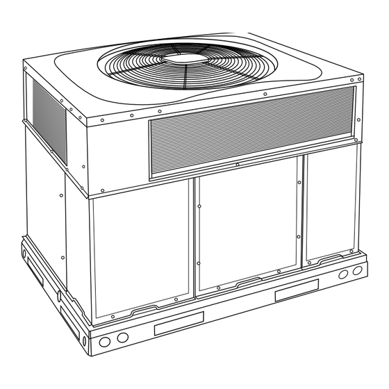
Fig. 1 - Unit PY5G
(Low NOx Model Available)
Safety Considerations
This unit is equipped with electrically powered safety measures. For the
safety measures to be effective, the unit must be electrically powered at
all times after installation, other than when servicing.
WARNING
!
PERSONAL INJURY AND PROPERTY DAMAGE
HAZARD
Continuous fan mode required for proper functioning. Installation must
meet the Required Minimum Dissipation Airflow as outlined in the
Leak Dissipation System section. Follow instructions in the
Continuous Fan Speed Set-Up section to change speeds.
Improper installation, adjustment, alteration, service maintenance, or use
can cause explosion, fire, electrical shock, or other conditions which
Installation Instructions
A09183
may cause death, personal injury, or property damage. Consult a
qualified installer, service agency, or your distributor or branch for
information or assistance. The qualified installer or agency must use
factory-authorized kits or accessories when modifying this product.
Refer to the individual instructions packaged with the kits or accessories
when installing.
WARNING
!
PERSONAL INJURY AND PROPERTY DAMAGE
HAZARD
For continued performance, reliability, and safety, the only approved
accessories and replacement parts are those specified by the equipment
manufacturer. The use of non-manufacturer approved parts and
accessories could invalidate the equipment limited warranty and result
in fire risk, equipment malfunction, and failure. Please review
manufacturer's instructions and replacement part catalogs available
from your equipment supplier.
Auxiliary devices which may be a POTENTIAL IGNITION SOURCE
shall not be installed in the duct work. Examples of such POTENTIAL
IGNITION SOURCES are hot surfaces with a temperature exceeding
1292°F (700°C) and electric switching devices.
Electrostatic air purifiers installed in the ductwork are permitted, if the
purifier has an airflow sensor.
False ceilings or drop ceilings must not be used as a return air
duct/plenum.
This self-contained unit is already charged with refrigerant for optimum
performance, and shouldn't require any adjustments. Should any
installation/service work on the A2L refrigerant system be needed,
non-sparking tools are required. If the refrigerant system is opened, a
refrigerant detector should be used to check for leaks. Open flames or
other ignition sources should not be present, except during brazing.
Brazing should only take place on refrigerant tubes that are open to the
atmosphere or have been properly evacuated.
Follow all safety codes. Wear safety glasses, protective clothing, and
work gloves. Have a fire extinguisher available. Read these instructions
thoroughly and follow all warnings or cautions included in literature and
attached to the unit. consult local building codes, the current editions of
the National Fuel Gas Code (NFGC) NFPA 54/ANSI Z223.1, and the
National Electrical Code (NEC) NFPA 70.
In Canada refer to the current editions of the National Standards of
Canada CAN/CSA-B149.1 and 2 Natural Gas and Propane Installation
codes, and Canadian Electrical Code CSA C22.1
Recognize safety information. This is the safety-alert symbol
you see this symbol on the unit and in instructions or manuals, be alert to
the potential for personal injury. Understand these signal words: DAN-
GER, WARNING, and CAUTION. These words are used with the safe-
ty-alert symbol. DANGER identifies the most serious hazards which will
result in severe personal injury or death. WARNING signifies hazards
which could result in personal injury or death. CAUTION is used to iden-
tify unsafe practices which may result in minor personal injury or product
. When
Advertisement

Related Manuals for Carrier PY5G B Series


Summary of Contents for Carrier PY5G B Series
-
Page 1: Table Of Contents
PY5G--B 13.4 SEER2 Single-Packaged Air Conditioner and Gas Furnace System with R-454B Refrigerant Single Phase 2-5 Nominal Tons (Sizes 24-60) Three Phase 3-5 Nominal Tons (Sizes 36-60) Installation Instructions IMPORTANT: Effective January 1, 2023, all split system and packaged may cause death, personal injury, or property damage. Consult a air conditioners must be installed pursuant to applicable regional qualified installer, service agency, or your distributor or branch for efficiency standards issued by the Department of Energy. -
Page 2: Introduction
PY5G--B: Installation Instructions and property damage. NOTE is used to highlight suggestions which will WARNING result in enhanced installation, reliability, or operation. WARNING PERSONAL INJURY AND PROPERTY DAMAGE HAZARD For continued performance, reliability, and safety, the only approved CARBON MONOXIDE POISONING HAZARD accessories and replacement parts are those specified by the equipment Failure to follow this warning could result in personal injury and/or manufacturer. - Page 3 PY5G--B: Installation Instructions Step 3 – Field Fabricate Ductwork responsible for any damage incurred in transit. Check all items against shipping list. Immediately notify the nearest equipment distribution Secure all ducts to roof curb and building structure on vertical discharge office if any item is missing.
- Page 4 PY5G--B: Installation Instructions 2. Instruction in any special operation or precaution. 3. Condition of the load as it relates to operation of the lifting kit, such as balance, temperature, etc. Follow all applicable safety codes. Wear safety shoes and work gloves. Inspection Prior to initial use, and at monthly intervals, all rigging shackles, clevis pins, and straps should be visually inspected for any damage, evidence...
- Page 5 PY5G--B: Installation Instructions A230480 Fig. 3 – PY4G 24-30 Unit Dimensions Manufacturer reserves the right to change, at any time, specifications and designs without notice and without obligations.
- Page 6 PY5G--B: Installation Instructions A230481 Fig. 4 – PY4G 36-60 Dimensions Manufacturer reserves the right to change, at any time, specifications and designs without notice and without obligations.
- Page 7 PY5G--B: Installation Instructions SMALL/COMMON CURB SMALL SUPPLY BASE UNIT LARGE BASE RETURN UNIT UNIT PLACEMENT ON COMMON CURB SMALL OR LARGE BASE UNIT LARGE CURB A180216 B (large B (small / common UNIT CATALOG base) base) SIZE NUMBER IN. (mm) IN.
- Page 8 PY5G--B: Installation Instructions CAUTION - NOTICE TO RIGGERS PRUDENCE - AVIS AUX MANIPULATEUR ACCESS PANELS MUST BE IN PLACE WHEN RIGGING. PANNEAUX D'ACCES DOIT ÊTRE EN PLACE POUR MANIPULATION. Use top skid as spreader bar. / Utiliser la palette du haut comme barre de répartition DUCTS MINIMUM HEIGHT: 36"...
- Page 9 PY5G--B: Installation Instructions Table 1 – Physical Data UNIT SIZE 24040 24060 30040 30060 36060 36090 42060 42090 NOMINAL CAPACITY (ton) 2-1/2 2-1/2 3-1/2 3-1/2 SHIPPING WEIGHT lb. SHIPPING WEIGHT (kg) COMPRESSOR / QUANTITY Scroll / 1 REFRIGERANT (R-454B) Quantity lb. 5.75 6.25 6.75...
- Page 10 PY5G--B: Installation Instructions Table 1—Physical Data (Continued) UNIT SIZE 48090 48115 48130 60090 60115 60130 NOMINAL CAPACITY (ton) SHIPPING WEIGHT lb SHIPPING WEIGHT kg COMPRESSOR / QUANTITY Scroll / 1 REFRIGERANT (R-454B) Quantity lb 8.25 Quantity (kg.) MINIMUM CONDITIONED SPACE AREA (sq. ft.) REFRIGERANT METERING DEVICE Orifice ORIFICE ID in./mm...
- Page 11 PY5G--B: Installation Instructions These models meet the California maximum oxides of nitrogen (NOx) Use a minimum of one hanger every 6 ft (1.8 m). For pipe sizes emissions requirements of 40 nanograms/joule or less as shipped from larger than 1/2 in., follow recommendations of national codes. the factory.
- Page 12 PY5G--B: Installation Instructions Table 2 – Gas Flow Capacity † NOMINAL INTERNAL LENGTH OF PIPE FT (m) IRON PIPE DIAMETER SIZE (IN.) (IN.) (12) (15) (18) (21) (24) (27) (30) (38) (46) (53) (61) .622 — — .824 1.049 1-1/4 1.380 1400 1-1/2...
- Page 13 PY5G--B: Installation Instructions CAUTION Basepan UNIT COMPONENT DAMAGE HAZARD Downflow (Vertical) Basepan Failure to follow this caution may result in damage to the unit being Supply Downflow installed. Knockout (Vertical) Return Make all electrical connections in accordance with NFPA 70 Knockout (NEC) (latest edition) and local electrical codes governing such wiring.
- Page 14 PY5G--B: Installation Instructions Three-phase units: 1. Run the high-voltage (L1, L2, L3) and ground lead into the control box. HIGH VOLTAGE POWER LEADS POWER 2. Connect ground lead to chassis ground connection. (SEE UNIT WIRING SUPPLY LABEL) 3. Locate the black and yellow wires connected to the line side of the 3-PHASE SHOWN contactor (if equipped).
- Page 15 PY5G--B: Installation Instructions Table 4 – Required Operational Checks to Ensure Proper Dissipation System Function Indoor Electric/Gas Test # T-Stat Call Compressor Heat Normal Operation None Cool Heat Dissipation Activated None Cool Heat Required Minimum Dissipation Airflow The Required Minimum Dissipation Airflow is listed in Table 1, is based on refrigerant charge, and must be met or exceeded in Continuous Fan...
-
Page 16: Pre-Start-Up
PY5G--B: Installation Instructions board or Integrated Gas Controller. Replace fuse as required with correct 4. Verify the following conditions: size and rating. a. Make sure gas line is free of air. Before lighting the unit for the first time, perform the following with the gas valve in the OFF Pre-Start-up position: NOTE: If the gas supply pipe was not purged before connecting the... - Page 17 PY5G--B: Installation Instructions Leak detection equipment shall be calibrated to R-454B. If a leak above 20% of the LFL is found, proceed to recovery. 6. Shut off power to unit. 7. Before beginning recovery of the refrigerant: a. Make sure that handling equipment is available, if needed, to handle the refrigerant recovery cylinders.
- Page 18 PY5G--B: Installation Instructions Check Gas Input CAUTION Check gas input and manifold pressure after unit start-up (See Table If adjustment is required proceed as follows: UNIT DAMAGE HAZARD • The rated gas inputs shown in Table 7 are for altitudes from sea level Failure to follow this caution may result in reduced unit and/or to 2000 ft (610 m) above sea level.
- Page 19 PY5G--B: Installation Instructions EXAMPLE: Assume that the size of test dial is 1 cu ft, one revolution 3. Replace regulator cover screw on gas valve (See Fig. 16). 4. Turn off gas supply to unit. Remove manometer from pressure tap takes 32 sec, and the heating value of the gas is 1050 Btu/ft .
- Page 20 PY5G--B: Installation Instructions A240119 Fig. 17 – 208/230-1-60 Connection Wiring Diagram Manufacturer reserves the right to change, at any time, specifications and designs without notice and without obligations.
- Page 21 PY5G--B: Installation Instructions A240120 Fig. 18 – 208/230-1-60 Ladder Wiring Diagram Manufacturer reserves the right to change, at any time, specifications and designs without notice and without obligations.
- Page 22 PY5G--B: Installation Instructions A240122 Fig. 19 – 208/230-3-60 Connection Wiring Diagram Manufacturer reserves the right to change, at any time, specifications and designs without notice and without obligations.
- Page 23 PY5G--B: Installation Instructions A240123 Fig. 20 – 208/230-3-60 Ladder Wiring Diagram Manufacturer reserves the right to change, at any time, specifications and designs without notice and without obligations.
- Page 24 PY5G--B: Installation Instructions A240121 Fig. 21 – 460-3-60 Connection Wiring Diagram Manufacturer reserves the right to change, at any time, specifications and designs without notice and without obligations.
- Page 25 PY5G--B: Installation Instructions A240124 Fig. 22 – 460-3-60 Ladder Wiring Diagram Manufacturer reserves the right to change, at any time, specifications and designs without notice and without obligations.
- Page 26 PY5G--B: Installation Instructions Normal Operation Rollout Switch An LED (light-emitting diode) indicator is provided on the integrated The function of the rollout switch is to close the main gas valve in the gas unit controller (IGC) to monitor operation. The IGC is located by event of flame rollout.
- Page 27 PY5G--B: Installation Instructions The charging label and the tables shown refer to system temperatures WARNING and pressures in cooling mode only. A refrigerant charging label is attached to the inside of the compressor access panel. (See Table 10 ELECTRICAL SHOCK HAZARD Subcool chart for units with TXV and superheat chart for units with fixed orifice.) The chart includes the required liquid line temperature at Failure to follow this warning could result in personal injury or death.
- Page 28 PY5G--B: Installation Instructions Continuous Fan Speed Set-up: To change continuous fan speed: 1. Remove existing speed tap wire from the “FAN” terminal on the IGC. 2. Connect the desired speed tap wire on the “FAN” terminal on the IGC board. Table 9 –...
- Page 29 PY5G--B: Installation Instructions Table 10 – Cooling Charging Chart Superheat charging table is derived from optimum performance point. (95°F [35°C] outdoor ambient and (80°F [27°C] dry bulb; 67°F [19°C] wet bulb indoor condition.) Where a dash (-) appears do not attempt to check charge or charge unit under these conditions using the superheat method. (Weigh in method should be used.) A240114 A240115 Manufacturer reserves the right to change, at any time, specifications and designs without notice and without obligations.
- Page 30 Table 11 – Dry Coil Air Delivery* - Horizontal and Downflow Discharge Sizes 24-60 Heating ESP (in. W.C.) Allowable Unit Size Rise Motor Speed Functions 0.07 0.08 0.08 0.09 Low† Blue Alternate Heating Gas Heat Rise ( Gas Heat Rise ( 0.12 0.13 0.13...
- Page 31 Table 11 – Dry Coil Air Delivery* - Horizontal and Downflow Discharge Sizes 24-60 (Continued) Heating ESP (in. W.C.) Allowable Unit Size Rise Motor Speed Functions 0.09 0.10 0.11 0.11 0.11 Low† Blue Alternate Heating Gas Heat Rise ( Gas Heat Rise ( 0.14 0.15 0.15...
- Page 32 Table 11 – Dry Coil Air Delivery* - Horizontal and Downflow Discharge Sizes 24-60 (Continued) Heating ESP (in. W.C.) Allowable Unit Size Rise Motor Speed Functions 1096 1044 Alternate Cooling, 0.14 0.15 0.16 0.18 0.19 0.19 0.20 0.21 0.22 0.23 Low†...
- Page 33 Table 11 – Dry Coil Air Delivery* - Horizontal and Downflow Discharge Sizes 24-60 (Continued) Heating ESP (in. W.C.) Allowable Unit Size Rise Motor Speed Functions 0.13 0.13 0.14 0.15 0.16 0.16 0.17 0.18 0.18 0.19 Low† Blue Alternate Heating Gas Heat Rise ( Gas Heat Rise ( 1201...
- Page 34 Table 11 – Dry Coil Air Delivery* - Horizontal and Downflow Discharge Sizes 24-60 (Continued) Heating ESP (in. W.C.) Allowable Unit Size Rise Motor Speed Functions 0.05 0.06 0.06 0.07 0.07 0.08 0.08 0.09 Low† Blue Gas Heat Rise ( Gas Heat Rise ( 1437 1395...
- Page 35 Table 11 – Dry Coil Air Delivery* - Horizontal and Downflow Discharge Sizes 24-60 (Continued) Heating ESP (in. W.C.) Allowable Unit Size Rise Motor Speed Functions 0.05 0.06 0.06 0.07 0.07 0.08 0.08 0.09 Low† Blue Gas Heat Rise ( Gas Heat Rise ( 1437 1395...
- Page 36 Table 11 – Dry Coil Air Delivery* - Horizontal and Downflow Discharge Sizes 24-60 (Continued) Heating ESP (in. W.C.) Allowable Unit Size Rise Motor Speed Functions 0.05 0.06 0.06 0.07 0.07 0.08 0.08 0.09 Low† Blue Gas Heat Rise ( Gas Heat Rise ( 1437 1395...
- Page 37 Table 12 – Wet Coil Pressure Drop (IN. W.C.) Standard CFM (SCFM) Unit Size 1000 1100 1200 1300 1400 1500 1600 1700 1800 1900 2000 2100 2200 0.03 0.04 0.04 0.05 0.06 0.05 0.06 0.07 0.08 0.11 0.06 0.06 0.09 0.10 0.11 0.14...
-
Page 38: Maintenance
PY5G--B: Installation Instructions Maintenance 6. Check and inspect heating section before each heating season. Clean and adjust when necessary. To ensure continuing high performance and to minimize the possibility 7. Check flue hood and remove any obstructions, if necessary. of premature equipment failure, periodic maintenance must be Air Filter performed on this equipment. - Page 39 PY5G--B: Installation Instructions season. For the first heating season, inspect blower wheel bimonthly to WARNING determine proper cleaning frequency. To inspect blower wheel, remove draft hood assembly. Shine a flashlight FIRE, EXPLOSION HAZARD into opening to inspect wheel. If cleaning is required, remove induced-draft blower assembly as follows: Failure to follow this warning could result in personal injury, death or property damage.
- Page 40 PY5G--B: Installation Instructions Outdoor Fan WARNING UNIT OPERATION HAZARD Failure to follow this caution may result in damage to unit components. Keep the condenser fan free from all obstructions to ensure proper cooling operation. Never place articles on top of the unit. 1.
- Page 41 PY5G--B: Installation Instructions FAN GRILLE MOTOR MOTOR SHAFT A08505 Max Distance Between Top of Fan Grille and Bottom of Fan Blade “A” Size Fig. 28 – Fan Blade Position If no refrigerant leaks are found and low cooling performance is off, if possible, for most troubleshooting techniques.
-
Page 42: Troubleshooting
PY5G--B: Installation Instructions Flashing 1 hygroscopic, meaning it absorbs water readily. POE oils can absorb 15 times as much water as other oils designed for HCFC and CFC Check for refrigerant leaks using an independent R-454B detector. If no refrigerants. Take all necessary precautions to avoid exposure of the oil leaks are present, replace the sensor. - Page 43 PY5G--B: Installation Instructions Table 15 – Troubleshooting Chart SYMPTOM CAUSE REMEDY Power failure Call power company Fuse blown or circuit breaker tripped Replace fuse or reset circuit breaker Defective contactor, transformer, or high-pressure, Replace component loss-of-charge or low-pressure switch Compressor and condenser fan will not start. Insufficient line voltage Determine cause and correct Incorrect or faulty wiring...
- Page 44 PY5G--B: Installation Instructions Table 16 – Troubleshooting Guide–Heating SYMPTOM CAUSE REMEDY Water in gas line Drain. Install drip leg. No power to furnace Check power supply fuses, wiring or circuit breaker. Check transformer. No 24-v power supply to control circuit NOTE: Some transformers have internal over-current protection that requires a cool-down period to reset.
- Page 45 PY5G--B: Installation Instructions Table 18 – IGC Troubleshooting Guide–LED Status Codes SYMPTOM CAUSE REMEDY Check 5-amp fuse son IGC*, power to unit, 24-v circuit breaker, No Power or Hardware failure and transformer. Units without a 24-v circuit breaker have an Loss of power to control module (IGC)*.
- Page 46 PY5G--B: Installation Instructions Start-Up Checklist (Remove and Store in Job Files) I. PRELIMINARY INFORMATION MODEL NO.: ____________________________________________ SERIAL NO.: ____________________________________________ DATE: __________________________________________________ TECHNICIAN: ___________________________________________ II. PRESTART-UP (Insert check mark in box as each item is completed) (¦ ) VERIFY THAT ALL PACKING MATERIALS HAVE BEEN REMOVED FROM UNIT ( ) REMOVE ALL SHIPPING HOLD DOWN BOLTS AND BRACKETS PER INSTALLATION INSTRUCTIONS ( ) CHECK ALL ELECTRICAL CONNECTIONS AND TERMINALS FOR TIGHTNESS ( ) CHECK GAS PIPING FOR LEAKS (WHERE APPLICABLE)
- Page 47 Edition Date: 04/24 Catalog No: IM-PY5G-02 © 2024 Carrier. All rights reserved. A Proud Member of the Carrier Family Replaces: New Manufacturer reserves the right to change, at any time, specifications and designs without notice and without obligations.
Need help?
Do you have a question about the PY5G B Series and is the answer not in the manual?
Questions and answers