Advertisement
Quick Links
PGD4 Series K WPG4 Series K
13.4 SEER2 Single-Packaged Air Conditioner and
Gas Furnace System with R-410A Refrigerant
Single Phase 2-5 Nominal Tons (Sizes 24-60)
Three Phase 3-5 Nominal Tons (Sizes 36-60)
IMPORTANT: Effective January 1, 2015, all split system and packaged
air conditioners must be installed pursuant to applicable regional
efficiency standards issued by the Department of Energy.
NOTE:
Read the entire instruction manual before starting the
installation.
NOTE:
Installer: Make sure the Owner's Manual and Service
Instructions are left with the unit after installation.
Table of Contents
Safety Considerations . . . . . . . . . . . . . . . . . . . . . . . . . . . . . . . . . . . . . . . 1
Introduction. . . . . . . . . . . . . . . . . . . . . . . . . . . . . . . . . . . . . . . . . . . . . . . 2
Receiving and Installation . . . . . . . . . . . . . . . . . . . . . . . . . . . . . . . . . . . 2
Pre-Start-up . . . . . . . . . . . . . . . . . . . . . . . . . . . . . . . . . . . . . . . . . . . . . . 16
Start-up . . . . . . . . . . . . . . . . . . . . . . . . . . . . . . . . . . . . . . . . . . . . . . . . . 17
Maintenance . . . . . . . . . . . . . . . . . . . . . . . . . . . . . . . . . . . . . . . . . . . . . 45
Troubleshooting . . . . . . . . . . . . . . . . . . . . . . . . . . . . . . . . . . . . . . . . . . 49
Start-up Checklist . . . . . . . . . . . . . . . . . . . . . . . . . . . . . . . . . . . . . . . . . 49
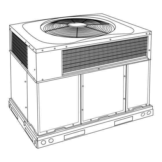
Fig. 1 - Unit PGD4, PGS4, WPG4
(Low NOx Model Available)
Safety Considerations
Improper installation, adjustment, alteration, service maintenance, or use
can cause explosion, fire, electrical shock, or other conditions which
may cause death, personal injury, or property damage. Consult a
qualified installer, service agency, or your distributor or branch for
information or assistance. The qualified installer or agency must use
factory-authorized kits or accessories when modifying this product.
Refer to the individual instructions packaged with the kits or accessories
when installing.
Follow all safety codes. Wear safety glasses, protective clothing, and
work gloves. Have a fire extinguisher available. Read these instructions
thoroughly and follow all warnings or cautions included in literature and
attached to the unit. consult local building codes, the current editions of
Installation Instructions
A170030
the National Fuel Gas Code (NFGC) NFPA 54/ANSI Z223.1, and the
National Electrical Code (NEC) NFPA 70.
In Canada refer to the current editions of the National Standards of
Canada CAN/CSA-B149.1 and 2 Natural Gas and Propane Installation
codes, and Canadian Electrical Code CSA C22.1
Recognize safety information. This is the safety-alert symbol
you see this symbol on the unit and in instructions or manuals, be alert to
the potential for personal injury. Understand these signal words: DAN-
GER, WARNING, and CAUTION. These words are used with the safe-
ty-alert symbol. DANGER identifies the most serious hazards which will
result in severe personal injury or death. WARNING signifies hazards
which could result in personal injury or death. CAUTION is used to iden-
tify unsafe practices which may result in minor personal injury or product
and property damage. NOTE is used to highlight suggestions which will
result in enhanced installation, reliability, or operation.
WARNING
!
CARBON MONOXIDE POISONING HAZARD
Failure to follow this warning could result in personal injury and/or
death.
Carbon Monoxide (CO) is a colorless, odorless, and tasteless poisonous
gas that can be fatal when inhaled. Follow all installation, maintenance,
and service instructions. See additional information below regarding
the installation of a CO Alarm.
Most states is the USA and jurisdictions in Canada have laws that
require the use of Carbon Monoxide (CO) alarms with fuel burning
products. Examples of fuel burning products are furnaces, boilers, space
heaters, generators, water heaters, stoves/ranges, clothes dryers,
fireplaces, incinerators, automobiles, and other internal combustion
engines. Even if there are no laws in your jurisdiction requiring a CO
Alarm, it's highly recommended that whenever any fuel burning product
is used in or around the home or business that the dwelling be equipped
with a CO Alarm(s). The Consumer Product Safety Commission
recommends the use of CO Alarm(s). The CO Alarm(s) must be
installed, operated, and maintained according to the CO Alarm
manufacturer's instructions. For more information about Carbon
Monoxide, local laws, or to purchase a CO Alarm only, please visit the
following website
https://www.kidde.com
WARNING
!
ELECTRICAL SHOCK HAZARD
Failure to follow this warning could result in personal injury or death.
Before installing or servicing system, always turn off main power to
system and install lockout tag. There may be more than one disconnect
switch. Turn off accessory heater power switch if applicable.
. When
Advertisement

Subscribe to Our Youtube Channel
Related Manuals for Carrier K WPG4 Series


Summary of Contents for Carrier K WPG4 Series
-
Page 1: Table Of Contents
PGD4 Series K WPG4 Series K 13.4 SEER2 Single-Packaged Air Conditioner and Gas Furnace System with R-410A Refrigerant Single Phase 2-5 Nominal Tons (Sizes 24-60) Three Phase 3-5 Nominal Tons (Sizes 36-60) Installation Instructions IMPORTANT: Effective January 1, 2015, all split system and packaged the National Fuel Gas Code (NFGC) NFPA 54/ANSI Z223.1, and the... -
Page 2: Introduction
PGD4 Series K WPG4 Series K: Installation Instructions NOTICE WARNING FIRE, EXPLOSION, ELECTRICAL SHOCK AND If the unit gasketing or insulation must be replaced, ensure the material used is compliant with the two agency requirements listed. CARBON MONOXIDE POISONING HAZARD Insulation and adhesives shall meet NFPA 90.1 requirements for... - Page 3 PGD4 Series K WPG4 Series K: Installation Instructions removing outer horizontal flange. other combustible materials. Slab-mounted units should be at least 2 in. (51 mm) above the highest expected water and runoff levels. Do not use CAUTION unit if it has been under water.
- Page 4 PGD4 Series K WPG4 Series K: Installation Instructions Lifting holes are provided in base rails as shown in Fig. 3 Fig. 1. Leave top shipping skid on the unit for use as a spreader bar to prevent the rigging straps from damaging the unit. If the skid is not available, use a spreader bar of sufficient length to protect the unit from damage.
- Page 5 PGD4 Series K WPG4 Series K: Installation Instructions A221500 Fig. 3 – PGD4 24-30 Unit Dimension Manufacturer reserves the right to change, at any time, specifications and designs without notice and without obligations.
- Page 6 PGD4 Series K WPG4 Series K: Installation Instructions A221501 Fig. 4 – PGD4 36-48 Unit Dimensions Manufacturer reserves the right to change, at any time, specifications and designs without notice and without obligations.
- Page 7 PGD4 Series K WPG4 Series K: Installation Instructions A221502 Fig. 5 – WPG4 24-30 Unit Dimension Manufacturer reserves the right to change, at any time, specifications and designs without notice and without obligations.
- Page 8 PGD4 Series K WPG4 Series K: Installation Instructions A221503 Fig. 6 – WPG4 36-48 Unit Dimensions Manufacturer reserves the right to change, at any time, specifications and designs without notice and without obligations.
- Page 9 PGD4 Series K WPG4 Series K: Installation Instructions SMALL/COMMON CURB SMALL SUPPLY BASE UNIT LARGE BASE RETURN UNIT UNIT PLACEMENT ON COMMON CURB SMALL OR LARGE BASE UNIT LARGE CURB A180216 B (large B (small / common UNIT CATALOG base)
- Page 10 PGD4 Series K WPG4 Series K: Installation Instructions CAUTION - NOTICE TO RIGGERS PRUDENCE - AVIS AUX MANIPULATEUR ACCESS PANELS MUST BE IN PLACE WHEN RIGGING. PANNEAUX D'ACCES DOIT ÊTRE EN PLACE POUR MANIPULATION. Use top skid as spreader bar. / Utiliser la palette du haut comme barre de répartition DUCTS MINIMUM HEIGHT: 36"...
- Page 11 PGD4 Series K WPG4 Series K: Installation Instructions Table 1 – Physical Data UNIT SIZE 24040 24060 30040 30060 36060 36090 42060 42090 NOMINAL CAPACITY (ton) 2-1/2 2-1/2 3-1/2 3-1/2 SHIPPING WEIGHT lb. SHIPPING WEIGHT (kg) COMPRESSOR / QUANTITY Scroll / 1 REFRIGERANT (R-410A) Quantity lb.
- Page 12 PGD4 Series K WPG4 Series K: Installation Instructions Table 1—Physical Data (Continued) UNIT SIZE 48090 48115 48130 60090 60115 60130 NOMINAL CAPACITY (ton) SHIPPING WEIGHT lb SHIPPING WEIGHT kg COMPRESSOR / QUANTITY Scroll / 1 REFRIGERANT (R-410A) Quantity lb 10.0 10.0...
- Page 13 PGD4 Series K WPG4 Series K: Installation Instructions These models meet the California maximum oxides of nitrogen (NOx) 2. When flexible connectors are used, the maximum length shall not emissions requirements of 40 nanograms/joule or less as shipped from exceed 36 in. (915 mm).
- Page 14 PGD4 Series K WPG4 Series K: Installation Instructions 4. To remove the downshot (plastic) knockouts for both supply and WARNING returns, break front and right side connecting tabs with a screwdriver and hammer. Push cover down to break rear and left FIRE OR EXPLOSION HAZARD side tabs.
- Page 15 PGD4 Series K WPG4 Series K: Installation Instructions 5. Size all ductwork for maximum required airflow (either heating or The unit must have a separate electrical service with a field-supplied, cooling) for unit being installed. Avoid abrupt duct size increases or waterproof disconnect switch mounted at, or within sight from, the unit.
-
Page 16: Pre-Start-Up
PGD4 Series K WPG4 Series K: Installation Instructions Pre-Start-up Use no. 18 American Wire Gage (AWG) color-coded, insulated (35°C minimum) wires to make the control voltage connections between the WARNING thermostat and the unit. If the thermostat is located more than 100 ft (30.5 m) from the unit (as measured along the control voltage wires), use... -
Page 17: Start-Up
PGD4 Series K WPG4 Series K: Installation Instructions 4. Verify the following conditions: Follow the lighting instructions on the heating section operation label a. Make sure gas line is free of air. Before lighting the unit for the (located on the inside of the control access panel) to start the heating first time, perform the following with the gas valve in the OFF section. - Page 18 PGD4 Series K WPG4 Series K: Installation Instructions unit controller (IGC) has the capability to automatically reduce the CAUTION evaporator “ON” delay and increase the evaporator “OFF” delay in the event of high duct static and/or partially-clogged filter. UNIT DAMAGE HAZARD...
- Page 19 PGD4 Series K WPG4 Series K: Installation Instructions 1. 32 sec. to complete one revolution. 3. Replace regulator cover screw on gas valve (See Fig. 15). 2. 3600 ¸ 32 = 112.5. 4. Turn off gas supply to unit. Remove manometer from pressure tap and replace pipe plug on gas valve.
- Page 20 PGD4 Series K WPG4 Series K: Installation Instructions A221583 Fig. 16 – 208/230-1-60 Connection Wiring Diagram Manufacturer reserves the right to change, at any time, specifications and designs without notice and without obligations.
- Page 21 PGD4 Series K WPG4 Series K: Installation Instructions A221584 Fig. 17 – 208/230-1-60 Ladder Wiring Diagram Manufacturer reserves the right to change, at any time, specifications and designs without notice and without obligations.
- Page 22 PGD4 Series K WPG4 Series K: Installation Instructions A221581 Fig. 18 – 208/230-3-60 Connection Wiring Diagram Manufacturer reserves the right to change, at any time, specifications and designs without notice and without obligations.
- Page 23 PGD4 Series K WPG4 Series K: Installation Instructions A221582 Fig. 19 – 208/230-3-60 Ladder Wiring Diagram Manufacturer reserves the right to change, at any time, specifications and designs without notice and without obligations.
- Page 24 PGD4 Series K WPG4 Series K: Installation Instructions A221579 Fig. 20 – 460-3-60 Connection Wiring Diagram Manufacturer reserves the right to change, at any time, specifications and designs without notice and without obligations.
- Page 25 PGD4 Series K WPG4 Series K: Installation Instructions A221580 Fig. 21 – 460-3-60 Ladder Wiring Diagram Normal Operation Table 9 show the approved temperature rise range for each heating input, and the air delivery CFM at various temperature rises for a given An LED (light-emitting diode) indicator is provided on the integrated external static pressure.
- Page 26 PGD4 Series K WPG4 Series K: Installation Instructions Heating Sequence of Operation Checking Cooling Control Operation (See Fig. Fig. 17 and unit wiring label) Start and check the unit for proper cooling control operation as follows: On a call for heating, terminal W of the thermostat is energized, starting 1.
- Page 27 PGD4 Series K WPG4 Series K: Installation Instructions CFM/Ton) for use with either a dehumidistat or a thermostat that CAUTION supports dehumidification. This unit is factory-set for use with a single cooling fan speed. For single UNIT DAMAGE HAZARD phase models, the cooling speed is marked “COOL” on the IGC (See Fig.
- Page 28 PGD4 Series K WPG4 Series K: Installation Instructions Table 7 – Color Coding for Indoor Fan Motor Leads Black = High Speed Orange = Med-High Speed Red = Med Speed Pink = Med-Low Speed Blue = Low Speed Cooling Sequence of Operation...
- Page 29 Table 8 – Cooling Charging Chart Superheat charging table is derived from optimum performance point. (95°F [35°C] outdoor ambient and (80°F [27°C] dry bulb; 67°F [19°C] wet bulb indoor condition.) Where a dash (-) appears do not attempt to check charge or charge unit under these conditions using the superheat method.
- Page 30 Table 9 – Dry Coil Air Delivery* - Horizontal and Downflow Discharge Sizes 24-60 Heating ESP (in. W.C.) Allowable Unit Size Rise Motor Speed Functions 0.07 0.08 0.08 0.09 Low† Blue Alternate Heating Gas Heat Rise ( Gas Heat Rise ( 0.12 0.13 0.13...
- Page 31 Table 9 – Dry Coil Air Delivery* - Horizontal and Downflow Discharge Sizes 24-60 (Continued) Heating ESP (in. W.C.) Allowable Unit Size Rise Motor Speed Functions 0.07 0.08 0.08 0.09 Low† Blue Gas Heat Rise ( Gas Heat Rise ( 0.12 0.13 0.13...
- Page 32 Table 9 – Dry Coil Air Delivery* - Horizontal and Downflow Discharge Sizes 24-60 (Continued) Heating ESP (in. W.C.) Allowable Unit Size Rise Motor Speed Functions 0.09 0.10 0.11 0.11 0.11 Low† Blue Alternate Heating Gas Heat Rise ( Gas Heat Rise ( 0.14 0.15 0.15...
- Page 33 Table 9 – Dry Coil Air Delivery* - Horizontal and Downflow Discharge Sizes 24-60 (Continued) Heating ESP (in. W.C.) Allowable Unit Size Rise Motor Speed Functions 0.09 0.10 0.11 0.11 0.11 Low† Blue Gas Heat Rise ( Gas Heat Rise ( 0.14 0.15 0.15...
- Page 34 Table 9 – Dry Coil Air Delivery* - Horizontal and Downflow Discharge Sizes 24-60 (Continued) Heating ESP (in. W.C.) Allowable Unit Size Rise Motor Speed Functions 1096 1044 Alternate Cooling, 0.14 0.15 0.16 0.18 0.19 0.19 0.20 0.21 0.22 0.23 Low†...
- Page 35 Table 9 – Dry Coil Air Delivery* - Horizontal and Downflow Discharge Sizes 24-60 (Continued) Heating ESP (in. W.C.) Allowable Unit Size Rise Motor Speed Functions 1096 1044 Alternate Cooling, 0.14 0.15 0.16 0.18 0.19 0.19 0.20 0.21 0.22 0.23 Low†...
- Page 36 Table 9 – Dry Coil Air Delivery* - Horizontal and Downflow Discharge Sizes 24-60 (Continued) Heating ESP (in. W.C.) Allowable Unit Size Rise Motor Speed Functions 0.13 0.13 0.14 0.15 0.16 0.16 0.17 0.18 0.18 0.19 Low† Blue Alternate Heating Gas Heat Rise ( Gas Heat Rise ( 1201...
- Page 37 Table 9 – Dry Coil Air Delivery* - Horizontal and Downflow Discharge Sizes 24-60 (Continued) Heating ESP (in. W.C.) Allowable Unit Size Rise Motor Speed Functions 0.13 0.13 0.14 0.15 0.16 0.16 0.17 0.18 0.18 0.19 Low† Blue Gas Heat Rise ( Gas Heat Rise ( 1201 1153...
- Page 38 Table 9 – Dry Coil Air Delivery* - Horizontal and Downflow Discharge Sizes 24-60 (Continued) Heating ESP (in. W.C.) Allowable Unit Size Rise Motor Speed Functions 0.05 0.06 0.06 0.07 0.07 0.08 0.08 0.09 Low† Blue Gas Heat Rise ( Gas Heat Rise ( 1437 1395...
- Page 39 Table 9 – Dry Coil Air Delivery* - Horizontal and Downflow Discharge Sizes 24-60 (Continued) Heating ESP (in. W.C.) Allowable Unit Size Rise Motor Speed Functions 0.05 0.06 0.06 0.07 0.07 0.08 0.08 0.09 Low† Blue Gas Heat Rise ( Gas Heat Rise ( 1437 1395...
- Page 40 Table 9 – Dry Coil Air Delivery* - Horizontal and Downflow Discharge Sizes 24-60 (Continued) Heating ESP (in. W.C.) Allowable Unit Size Rise Motor Speed Functions 0.05 0.06 0.06 0.07 0.07 0.08 0.08 0.09 Low† Blue Gas Heat Rise ( Gas Heat Rise ( 1437 1395...
- Page 41 Table 9 – Dry Coil Air Delivery* - Horizontal and Downflow Discharge Sizes 24-60 (Continued) Heating ESP (in. W.C.) Allowable Unit Size Rise Motor Speed Functions 0.05 0.06 0.06 0.07 0.07 0.08 0.08 0.09 Low† Blue Alternate Heating Gas Heat Rise ( Gas Heat Rise ( 1437 1395...
- Page 42 Table 9 – Dry Coil Air Delivery* - Horizontal and Downflow Discharge Sizes 24-60 (Continued) Heating ESP (in. W.C.) Allowable Unit Size Rise Motor Speed Functions 0.05 0.06 0.06 0.07 0.07 0.08 0.08 0.09 Low† Blue Gas Heat Rise ( Gas Heat Rise ( 1437 1395...
- Page 43 Table 9 – Dry Coil Air Delivery* - Horizontal and Downflow Discharge Sizes 24-60 (Continued) Heating ESP (in. W.C.) Allowable Unit Size Rise Motor Speed Functions 0.05 0.06 0.06 0.07 0.07 0.08 0.08 0.09 Low† Blue Gas Heat Rise ( Gas Heat Rise ( 1437 1395...
- Page 44 Table 10 – Wet Coil Pressure Drop (IN. W.C.) Standard CFM (SCFM) Unit Size 1000 1100 1200 1300 1400 1500 1600 1700 1800 1900 2000 2100 2200 0.03 0.04 0.04 0.05 0.06 0.05 0.06 0.07 0.08 0.11 0.06 0.06 0.09 0.10 0.11 0.14...
-
Page 45: Maintenance
PGD4 Series K WPG4 Series K: Installation Instructions Maintenance 6. Check and inspect heating section before each heating season. Clean and adjust when necessary. To ensure continuing high performance and to minimize the possibility 7. Check flue hood and remove any obstructions, if necessary. - Page 46 PGD4 Series K WPG4 Series K: Installation Instructions season. For the first heating season, inspect blower wheel bimonthly to WARNING determine proper cleaning frequency. To inspect blower wheel, remove draft hood assembly. Shine a flashlight FIRE, EXPLOSION HAZARD into opening to inspect wheel. If cleaning is required, remove...
- Page 47 PGD4 Series K WPG4 Series K: Installation Instructions Integrated Gas Unit Controller (IGC) Auto Transformer fuses used on 460 volt units only. (Hidden) Interface Fan Board (IFB) Induced Draft Motor Fan Partition Flue Rollout Mounting Collector Inducer Switch Burner Bracket...
- Page 48 PGD4 Series K WPG4 Series K: Installation Instructions FAN GRILLE MOTOR MOTOR SHAFT A08505 Max Distance Between Top of Fan Grille and Bottom of Fan Blade “A” Size Fig. 27 – Fan Blade Position specifically designed to operate with R-410A systems. R-22 pressure switches must not be used as replacements for the R-410A system.
-
Page 49: Troubleshooting
PGD4 Series K WPG4 Series K: Installation Instructions 3. Place terry cloth shop towel inside unit immediately under WARNING component(s) to be serviced and prevent lubricant run-offs through the louvered openings in the unit base. FIRE/EXPLOSION HAZARD 4. Perform required service. - Page 50 PGD4 Series K WPG4 Series K: Installation Instructions Table 13 – Troubleshooting Chart SYMPTOM CAUSE REMEDY Power failure Call power company Fuse blown or circuit breaker tripped Replace fuse or reset circuit breaker Defective contactor, transformer, or high-pressure, Replace component loss-of-charge or low-pressure switch Compressor and condenser fan will not start.
- Page 51 PGD4 Series K WPG4 Series K: Installation Instructions Table 14 – Troubleshooting Guide–Heating SYMPTOM CAUSE REMEDY Water in gas line Drain. Install drip leg. No power to furnace Check power supply fuses, wiring or circuit breaker. Check transformer. No 24-v power supply to control circuit NOTE: Some transformers have internal over-current protection that requires a cool-down period to reset.
- Page 52 PGD4 Series K WPG4 Series K: Installation Instructions Table 15 – Troubleshooting Guide–LED Status Codes SYMPTOM CAUSE REMEDY Check 5-amp fuse son IGC*, power to unit, 24-v circuit breaker, No Power or Hardware failure and transformer. Units without a 24-v circuit breaker have an Loss of power to control module (IGC)*.
- Page 53 PGD4 Series K WPG4 Series K: Installation Instructions Start-Up Checklist (Remove and Store in Job Files) I. PRELIMINARY INFORMATION MODEL NO.: ____________________________________________ SERIAL NO.: ____________________________________________ DATE: __________________________________________________ TECHNICIAN: ___________________________________________ II. PRESTART-UP (Insert check mark in box as each item is completed) (¦...
Need help?
Do you have a question about the K WPG4 Series and is the answer not in the manual?
Questions and answers