Advertisement
Quick Links
PAM4, WJA5
Single-Packaged Air Conditioner System
with R-454B Refrigerant
Single Phase
2 to 5 Nominal Tons (Sizes 024-060)
IMPORTANT:
Effective January 1, 2015, all split system and
packaged air conditioners must be installed pursuant to applicable
regional efficiency standards issued by the Department of Energy.
NOTE:
Read the entire instruction manual before starting the
installation.
Installer: Make sure the Owner's Manual and Service Instructions are
left with the unit after installation.
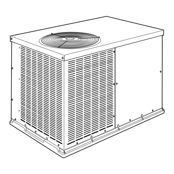
PAM4, WJA5 024-048
PAM4, WJA5 060
Fig. 1 – Unit PAM4, WJA5
Certified to leak 2% or less of nominal air conditioning CFM
delivered when pressurized to 1-in. W.C. with all present air inlets,
air outlets, and condensate drain port(s) sealed.
Table of Contents
Safety Considerations . . . . . . . . . . . . . . . . . . . . . . . . . . . . . . . . . . . . . 1
Introduction. . . . . . . . . . . . . . . . . . . . . . . . . . . . . . . . . . . . . . . . . . . . . 2
Receiving and Installation . . . . . . . . . . . . . . . . . . . . . . . . . . . . . . . . . 2
Transport and Storage Considerations . . . . . . . . . . . . . . . . . . . . . . 2
Installing factory-supplied duct flanges;. . . . . . . . . . . . . . . . . . . 4
Leak Dissipation System . . . . . . . . . . . . . . . . . . . . . . . . . . . . . 10
Installation Instructions
A10165
A150067
Leak Dissipation Control Board (DSB) . . . . . . . . . . . . . . . . . . 11
Pre-Start-up. . . . . . . . . . . . . . . . . . . . . . . . . . . . . . . . . . . . . . . . . . . . 11
Start-up . . . . . . . . . . . . . . . . . . . . . . . . . . . . . . . . . . . . . . . . . . . . . . . 12
Maintenance . . . . . . . . . . . . . . . . . . . . . . . . . . . . . . . . . . . . . . . . . . . 19
Air Filter . . . . . . . . . . . . . . . . . . . . . . . . . . . . . . . . . . . . . . . . . . 20
Unit Top Removal . . . . . . . . . . . . . . . . . . . . . . . . . . . . . . . . . . 20
Indoor Blower and Motor . . . . . . . . . . . . . . . . . . . . . . . . . . . . . 20
Outdoor Coil, Indoor Coil, and Condensate Drain Pan . . . . . . 21
Outdoor Fan Adjustment . . . . . . . . . . . . . . . . . . . . . . . . . . . . . 21
Electrical Controls and Wiring . . . . . . . . . . . . . . . . . . . . . . . . . 21
Refrigerant Circuit . . . . . . . . . . . . . . . . . . . . . . . . . . . . . . . . . . 22
Indoor Airflow . . . . . . . . . . . . . . . . . . . . . . . . . . . . . . . . . . . . . 22
Metering Devices . . . . . . . . . . . . . . . . . . . . . . . . . . . . . . . . . . . 22
High Flow Valves . . . . . . . . . . . . . . . . . . . . . . . . . . . . . . . . . . . 22
High Pressure Switch . . . . . . . . . . . . . . . . . . . . . . . . . . . . . . . . 22
R-454B Compressor . . . . . . . . . . . . . . . . . . . . . . . . . . . . . . . . . 22
Refrigerant . . . . . . . . . . . . . . . . . . . . . . . . . . . . . . . . . . . . . . . . 22
Compressor Oil. . . . . . . . . . . . . . . . . . . . . . . . . . . . . . . . . . . . . 22
Servicing Systems on Roofs with Synthetic Materials. . . . . . . 22
Synthetic Roof Precautionary Procedure . . . . . . . . . . . . . . . . . 22
Liquid Line Filter Drier . . . . . . . . . . . . . . . . . . . . . . . . . . . . . . 23
R-454B Refrigerant Charging. . . . . . . . . . . . . . . . . . . . . . . . . . 23
Troubleshooting . . . . . . . . . . . . . . . . . . . . . . . . . . . . . . . . . . . . . . . . 23
Sequence of Events - Dissipation Mode . . . . . . . . . . . . . . . . . . . 23
Flash Codes /Actions . . . . . . . . . . . . . . . . . . . . . . . . . . . . . . . . 23
No Power . . . . . . . . . . . . . . . . . . . . . . . . . . . . . . . . . . . . . . . . . 23
Flashing 1 . . . . . . . . . . . . . . . . . . . . . . . . . . . . . . . . . . . . . . . . . 23
Flashing 2 . . . . . . . . . . . . . . . . . . . . . . . . . . . . . . . . . . . . . . . . . 23
Flashing 3 . . . . . . . . . . . . . . . . . . . . . . . . . . . . . . . . . . . . . . . . . 23
Flashing 4 . . . . . . . . . . . . . . . . . . . . . . . . . . . . . . . . . . . . . . . . . 23
Flashing 5 . . . . . . . . . . . . . . . . . . . . . . . . . . . . . . . . . . . . . . . . . 23
Flashing 6 . . . . . . . . . . . . . . . . . . . . . . . . . . . . . . . . . . . . . . . . . 23
Flashing 7 . . . . . . . . . . . . . . . . . . . . . . . . . . . . . . . . . . . . . . . . . 23
Flashing 8 . . . . . . . . . . . . . . . . . . . . . . . . . . . . . . . . . . . . . . . . . 23
Start-up Checklist . . . . . . . . . . . . . . . . . . . . . . . . . . . . . . . . . . . . . . . 23
Decommissioning . . . . . . . . . . . . . . . . . . . . . . . . . . . . . . . . . . . . 27
Safety Considerations
This unit is equipped with electrically powered safety measures. For the
safety measures to be effective, the unit must be electrically powered at
all times after installation, other than when servicing.
WARNING
!
PERSONAL INJURY AND PROPERTY DAMAGE
HAZARD
Continuous fan mode required for proper functioning. Installation must
meet the Required Minimum Dissipation Airflow as outlined in the
Leak Dissipation System section. Follow instructions in the
Continuous Fan Speed Set-Up section to change speeds.
Advertisement

Related Manuals for Carrier PAM4


Summary of Contents for Carrier PAM4
- Page 1 PAM4, WJA5 060 safety measures to be effective, the unit must be electrically powered at Fig. 1 – Unit PAM4, WJA5 all times after installation, other than when servicing. Certified to leak 2% or less of nominal air conditioning CFM delivered when pressurized to 1-in.
- Page 2 PAM4, WJA5: Installation Instructions Improper installation, adjustment, alteration, service maintenance, or use hazards which could result in personal injury or death. CAUTION is can cause explosion, fire, electrical shock, or other conditions which used to identify unsafe practices which may result in minor personal may cause death, personal injury, or property damage.
- Page 3 PAM4, WJA5: Installation Instructions refer to national regulations, and follow the Decommissioning section in conditioning and ventilating systems, NFPA 90A or residence type, this manual. NFPA 90B and/or local codes and ordinances. Step 1 – Check Equipment Select and size ductwork, supply-air registers, and return air grilles...
- Page 4 PAM4, WJA5: Installation Instructions installation standards for residential heating and air conditioning systems. 5. Secure all ducts to building structure. Flash, weatherproof, and vibration-isolate duct openings in wall or roof according to good construction practices. Fig. 7 shows a typical duct system with unit installed.
- Page 5 PAM4, WJA5: Installation Instructions A240270 Fig. 4 – Unit Base Dimensions, PAM4, WJA5 024-036 Manufacturer reserves the right to change, at any time, specifications and designs without notice and without obligations.
- Page 6 PAM4, WJA5: Installation Instructions A240271 Fig. 5 – Unit Base Dimensions, PAM4, WJA5 042-048 Manufacturer reserves the right to change, at any time, specifications and designs without notice and without obligations.
- Page 7 PAM4, WJA5: Installation Instructions A240272 Fig. 6 – Unit Base Dimensions PAM4, WJA5 060 Manufacturer reserves the right to change, at any time, specifications and designs without notice and without obligations.
- Page 8 PAM4, WJA5: Installation Instructions INDOOR THERMOSTAT RETURN FROM TOP COVER POWER SOURCE POWER AND LOW-VOLTAGE DISCONNECT ENTRY PER NEC (UNIT AND COMPOSITE ELECTRIC RUST-PROOF HEATER) BASEPAN Power Wiring CONDENSATE DRAIN Control Wiring CONNECTION Condenser Airflow Evaporator Airflow A08207 Fig. 7 – Typical Installation Table 1 –...
- Page 9 PAM4, WJA5: Installation Instructions Table 2 – Minimum Airflow for Safe Electric Heater Operation Minimum Airflow (CFM) AC Unit Size 5 kW 7.5 kW 10 kW 15 kW 20 kW 1050 1050 1050 1600 1050 1600 X = Not Approved Combination Step 7 –...
- Page 10 PAM4, WJA5: Installation Instructions ROUTING POWER LEADS INTO UNIT Route thermostat wires through grommet providing a drip-loop at the panel. Connect low-voltage leads to the thermostat as shown in Fig. Use only copper wire between disconnect and unit. The high-voltage leads should be in a conduit until they enter the unit;...
- Page 11 PAM4, WJA5: Installation Instructions Leak Dissipation Control Board (DSB) Example: A 036 size unit will be installed in a residential home with a conditioned The leak dissipation control board (Fig. 14) is located in the control box. space of 1800 sq. ft. (Conditioned space to be served entirely by the There are 2 LED indicators, which are viewable after removing the unit).
- Page 12 PAM4, WJA5: Installation Instructions Start-up Step 1 – Check for Refrigerant Leaks BROWN WARNING EXPLOSION HAZARD Failure to follow this warning could result in death, serious personal injury, and/or property damage. GREEN Never use air or gases containing oxygen for...
- Page 13 PAM4, WJA5: Installation Instructions process shall be carried out prior to returning the compressor to the supplier. The crankcase electric heat may be used to accelerate the compressor evacuation process. A torch must not be used. When oil is drained from a system, it shall be carried out safely.
- Page 14 PAM4, WJA5: Installation Instructions Table 5 – Superheat Charging A240401 Table 6 – Required Subcooling A240400 Manufacturer reserves the right to change, at any time, specifications and designs without notice and without obligations.
- Page 15 PAM4, WJA5: Installation Instructions Step 3 – Refrigerant Charge 8. Add charge if the measured temperature is higher than the liquid line temperature value in the table. The refrigerant system is fully charged with R-454B refrigerant and is 9. Remove charge if the measured temperature is lower than the table tested and factory sealed.
- Page 16 PAM4, WJA5: Installation Instructions A240273 Fig. 16 – Single-Phase Connection Electrical Diagram Manufacturer reserves the right to change, at any time, specifications and designs without notice and without obligations.
- Page 17 PAM4, WJA5: Installation Instructions A240274 Fig. 17 – Single-Phase Ladder Electrical Diagram Manufacturer reserves the right to change, at any time, specifications and designs without notice and without obligations.
- Page 18 PAM4, WJA5: Installation Instructions A190339 Fig. 18 – Single-Phase Accessory Electric Heater Wiring Manufacturer reserves the right to change, at any time, specifications and designs without notice and without obligations.
- Page 19 PAM4, WJA5: Installation Instructions Table 7 – Wet Coil Air Delivery External Static Pressure (in. W.C.) Unit Speed Air Delivery Size Taps Color SCFM SCFM RED† SCFM 1000 SCFM 1041 1011 SCFM 1182 1131 1105 1060 1025 SCFM 1000 SCFM...
- Page 20 PAM4, WJA5: Installation Instructions cooling season and twice during the heating season if electric heat is WARNING installed, or whenever the filter becomes clogged with dust and lint. Unit Top Removal PERSONAL INJURY AND UNIT DAMAGE HAZARD NOTE: When performing maintenance or service procedures that...
- Page 21 PAM4, WJA5: Installation Instructions Table 9 – Accessory Electric Heat Pressure Drop (IN. W.C.) HEATER kW 1000 1200 1400 1600 1800 2000 2200 5-20 0.033 0.037 0.042 0.047 0.052 0.060 0.067 0.075 Outdoor Fan Adjustment 2. Remove the blower wheel from the housing: a.
- Page 22 PAM4, WJA5: Installation Instructions proper operation. If discrepancies are observed in operating cycle, or if a WARNING suspected malfunction has occurred, check each electrical component with the proper electrical instrumentation. Refer to the unit wiring label EXPLOSION HAZARD when making these checks (See Fig.
- Page 23 PAM4, WJA5: Installation Instructions Start-up Checklist 5. Remove and dispose of any oil contaminated material per local codes. Use the Start-Up Checklist at the back of this manual. Liquid Line Filter Drier The filter drier is specifically designed to operate with R-454B. Use only factory-authorized components.
- Page 24 PAM4, WJA5: Installation Instructions Table 10 – Troubleshooting Chart SYMPTOM CAUSE REMEDY Power failure Call power company Fuse blown or circuit breaker tripped Replace fuse or reset circuit breaker Defective contactor, transformer, control relay, or high-pressure, Compressor and outdoor fan...
- Page 25 PAM4, WJA5: Installation Instructions Table 11 – Dissipation Board Status Code Descriptions A240111 Manufacturer reserves the right to change, at any time, specifications and designs without notice and without obligations.
- Page 26 PAM4, WJA5: Installation Instructions Start-Up Checklist (Remove and Store in Job Files) I. PRELIMINARY INFORMATION MODEL NO.: SERIAL NO.: ____________________________________________ DATE: __________________________________________________ TECHNICIAN: ___________________________________________ II. PRESTART-UP (Insert check mark in box as each item is completed) ( ) VERIFY THAT ALL PACKING MATERIALS HAVE BEEN REMOVED FROM UNIT...
- Page 27 © 2024 Carrier. All rights reserved. Edition Date: 10/24 Catalog No: PAM4-WJA5-02SI A Proud Member of the Carrier Family Replaces: PAM4-WJA5-01SI Manufacturer reserves the right to change, at any time, specifications and designs without notice and without obligations.
Need help?
Do you have a question about the PAM4 and is the answer not in the manual?
Questions and answers