Table of Contents
Advertisement
220-240V ~, 50Hz
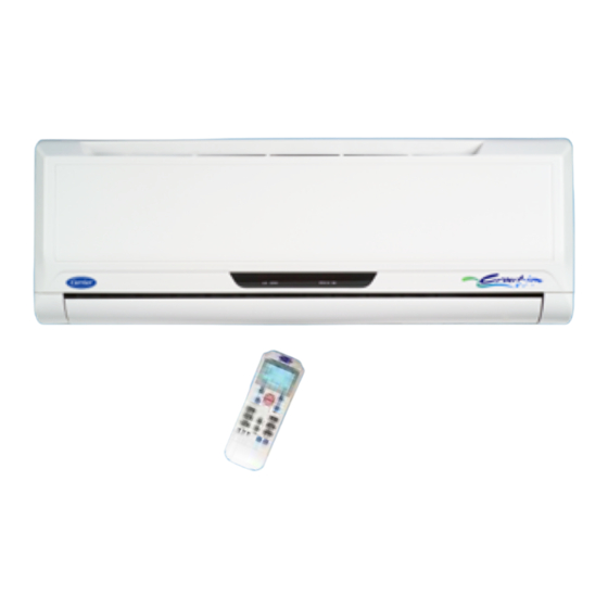
Hi Wall Split Air Conditioners
53KHET 12-18-24 Cool Only
53QHET 12-18-24 Heat Pump
INSTALLATION MANUAL
Carrier is committed to continuously improving its products according to national and international standards
to ensure the highest quality and reliability standards, and to meet market regulations and requirements.
All specifications subject to change without prior notice according to Carrier policy of continuous development.
Quality
Enviromental
Safety
Management System
Management System
Management System
ISO 9001 : 2008
ISO 14001 : 2004
BS OHSAS 18001 : 2007
Rev. (0) - 2012
03502821
Certi cate No.: QS-5519HH
Certi cate No : 12 104 30334 TMS
Certi cate No : 12 116 30334 TMS
Advertisement
Table of Contents

Related Manuals for Carrier 53KHET 12


Summary of Contents for Carrier 53KHET 12
-
Page 1: Installation Manual
Carrier is committed to continuously improving its products according to national and international standards to ensure the highest quality and reliability standards, and to meet market regulations and requirements. All specifications subject to change without prior notice according to Carrier policy of continuous development. Quality... -
Page 2: Table Of Contents
TABLE OF CONTENTS PAGE NO. 1. GENERAL NOTES TO INSTALLER 2. PRECAUTIONS BEFORE INSTALLATION 3. SPLIT SYSTEM DESCRIPTION 4. MODELS 5. OPERATING LIMITS 6. DIMENSIONS AND WEIGHT OF INDOOR UNIT 7. DIMENSIONS AND WEIGHT OF OUTDOOR UNIT 8. SELECTING INSTALLATION LOCATION OF INDOOR UNIT 9. -
Page 3: General Notes To Installer
1. GENERAL NOTES TO INSTALLER Split room air conditioner has been carefully designed and manufactured under strict Quality Control conditions. Therefore you are completely responsible for proper installation completion and operation of the air conditioner. Carefully read the manual carefully before proceeding with the installation to ensure correct installation. -
Page 4: Precautions Before Installation
7- Product normal sound ( refrigerant – moving parts – plastic parts ) 8- Inconvenience or commercial loss is not covered. The decision of Carrier in ascertaining the same will be final. Any such repairs will be carried - out at the expense of the owner ( purchaser ). -
Page 5: Split System Description
3. SPLIT SYSTEM DESCRIPTION Split System Models Sizes 12K – 18K Indoor Unit Air Inlet Outdoor Unit Air outlet Split System Model 24K Indoor Unit Air Inlet Outdoor Unit Air outlet 1: Remote control signal receiver. 2: LCD Display panel 3: Panel frame 4: Chassis 5: Front panel... -
Page 6: Models
= Hi Wall System = Elite Series = High Ambient = System Size = Nominal Power Supply 220-240V ~ 50Hz 1Ph = Wireless Remote Control = Miraco – Carrier = Ionizer 5. OPERATING LIMITS * COOLING HEATING Dry Bulb Wet Bulb... -
Page 7: Dimensions And Weight Of Indoor Unit
6. DIMENSIONS AND WEIGHT OF INDOOR UNIT DIMENSIONS (mm) Dimensions (mm) Indoor Unit Weight Type Model 42KHET12-708F Cool Only 42QHET12-708F Heat Pump 42KHET18-708F Cool Only 42QHET18-708F Heat Pump 42KHET24-708F Cool Only 1080 42QHET24-708F Heat Pump 7. DIMENSIONS AND WEIGHT OF OUTDOOR UNIT DIMENSIONS (mm) Mounting Unit... -
Page 8: Selecting Installation Location Of Indoor Unit
8. SELECTING INSTALLATION LOCATION OF INDOOR UNIT 8.1 CONSIDERATIONS OF SELECTING INSTALLATION LOCATION Select installation location which allows minimum clearances for free air circulation and easy accessibility for service and maintenance. Dimensions (mm) Back right outlet location • Select outlet location of piping from indoor unit which allows easy access to the ends of refrigerant piping lines to Back left... - Page 9 SELECTING INSTALLATION LOCATION OF INDOOR UNIT (Cont.) CONSIDERATIONS OF SELECTING INSTALLATION LOCATION (Cont.) Select installation location which permit the unit to deliver air to all of the space to be 1900 mm uniformly air-conditioned. or more Avoid installation of the indoor unit at too low a position.
-
Page 10: Selecting Installation Location Of Outdoor Unit
9. SELECTING INSTALLATION LOCATION OF OUTOOR UNIT INSTALLATION LOCATIONS The outdoor unit can be installed in any outside location, on a wall, on a roof or on a ground level. CONSIDERATIONS FOR SELECTING INSTALLATION LOCATIONS Avoid installation location which can lead to excessive distance between outdoor and indoor units to avoid alteration on system cooling and heating performance. - Page 11 SELECTING INSTALLATION LOCATION OF OUTOOR UNIT (Cont.) CONSIDERATIONS FOR SELECTING INSTALLATION LOCATION (Cont.) Select the installation location of outdoor unit which is able to support operating weight of outdoor unit, and not cause vibration. Select the installation location of outdoor unit which is far away from the direct sunlight.
- Page 12 SELECTING INSTALLATION LOCATION OF OUTOOR UNIT (Cont.) 9.3 MINIMUM CLEARANCES WHEN SELECTING INSTALLATION LOCATION FOR SINGLE OUTDOOR UNIT INSTALLATION Obstacle at unit front ( air outlet ) Select installation location which allows the minimum clearances shown in the figures for 500 mm free air circulation and easy accessibility for or more...
- Page 13 SELECTING INSTALLATION LOCATION OF OUTOOR UNIT (Cont.) 9.4 MINIMUM CLEARANCES WHEN SELECTING INSTALLATION LOCATION FOR SERIAL INSTALLATION OF MORE THAN ONE OUTDOOR UNIT Obstacle at unit front ( air outlet ) Select installation location which allows the 1000 mm minimum clearances shown in the figures for or more free air circulation and easy accessibility for service and maintenance :...
-
Page 14: Installation Location Check List
10. INSTALLATION LOCATION CHECK LIST (A) INDOOR UNIT - The installation location is close to the outdoor unit - The wall hole (required to pass refrigerant piping, electrical cables and drain line) is properly made as per installation required. - The installation location permit the unit to deliver air to all of the space to be air-conditioned - The installation location is far away from any sunlight - The installation location is far away from any heat sources... -
Page 15: Installtion Accessories
11. INSTALLATION ACCESSORIES 11.1 STANDARD INSTALLATION ACCESSORIES SUPPLIED FROM THE FACTORY DESCREPTION SHAPE Battery 1.5 volt size AAA To operate the wireless remote control alkaline type Wireless remote control To operate the air conditioner To illustrate control functions Owner manual of operation Installation Manual To illustrate installation instructions. - Page 16 INSTALLATION ACCESSORIES (Cont.) 11.4 OTHER INSTALLATION ACCESSORIES Not supplied from the factory but must be used in the installation field to complete installation. DESCREPTION USAGE Electrical Connection To electrically connect the indoor unit, the outdoor unit and circuit Cables breaker ـ...
-
Page 17: Installation Chart
12. INSTALLATION CHART 1) Installing outdoor unit 5) Connecting refrigerant 9) Air purging with piping lines a vacuum pump 2) Drilling hole thru the 6) Connecting condensate 10) Refrigerant leak test wall drain line 7) Connecting electrical 3) Installing indoor unit 11) Opening service valves wiring Outdoor... -
Page 18: Indoor Unit Installation
13. INDOOR UNIT INSTALLATION 13-1 PREPARATION STEPS BEFORE INSTALLATION STEP (1) :Selecting Wall Hole Location Back right or Back left piping : In case of passing refrigerant piping lines, electrical cables and condensate drain line behind the unit, drill a hole of 65mm behind the unit in one of the following locations as per the section : Right Side or Left Side Piping : In case of passing refrigerant piping lines, electrical cables and condensate drain line from unit right side or from unit left side, remove the pipe cover form the side panel. -
Page 19: Installation Steps
INDOOR UNIT INSTALLATION (Cont.) PREPARATION STEPS BEFORE INSTALLATION (Cont.) Step (2): Making Wall Hole Precautions: Wall Before making a hole, check carefully the following points : • The wall is flat and perpendicular. • If the wall is not flat and perpendicular, the indoor unit can be unstable and condensate drain can spill. -
Page 20: Indoor Unit 2
INDOOR UNIT INSTALLATION (Cont.) 13-2 INSTALLATION STEPS OF INDOOR UNIT Step (1) : Installing wall hang bracket • Allow the clearance space around the unit, which permits adequate air circulation, easy access to the unit for easy service and maintenance. •... - Page 21 INSTALLATION OF INDOOR UNIT (Cont.) INSTALLATION STEPS OF INDOOR UNIT (Cont.) Step (4): Install indoor unit on the wall hang bracket 1. Pass refrigerant piping lines, electrical cables and condensate drain line through the wall sleeve Upper hooker before hooking the indoor unit onto the top of the wall hang bracket.
-
Page 22: Remote Control Installation
14. REMOTE CONTROL INSTALLATION 14-1 HOW TO INSERT BATTERIES: (a) Remove the cover of battery (c) Press the button (at the front of remote compartment at the back of the control) with an object not sharp to operate remote control by pressing the the remote control. -
Page 23: Preparing Unit Before Installation
REMOTE CONTROL INSTALLATION (Cont.) 14-2 INSTRUCTIONS OF USING WIRELESS REMOTE CONTROL 1- The remote control must be directed toward the receiver of indoor unit when pressing the buttons of the desired functions. An acoustical acknowledgement sound (beep) will indicate that signal has been received. -
Page 24: Outdoor Unit Installation
15. OUTDOOR UNIT INSTALLATION 15.1 PREPARATION STEPS BEFORE INSTALLATION Put packed unit as shown. b. Lift unit from cardboard. c. Remove service door (item 2) by removing one screw (item 1). Detach the cable clamp by removing one screw. 15.2 WALL INSTALLATION STEPS Wall Support Parts Part Description Right Side... -
Page 25: Connecting Refrigerant Piping Lines
16. CONNECTING REFRIGERANT PIPING LINES 16-1 REFRIGERANT CONNECTIONS CHART (1) Pipes Flaring (2) Pipes Connections (3) Air Purging (4) Leak Check (5) Pipes Insulation (6) Opening Valves... - Page 26 CONNECTING REFRIGERANT PIPING LINES (Cont.) 16-2 POSSIBLE OUTLET LOCATIONS OF REFRIGERANT PIPING LINES FROM INDOOR UNIT The refrigerant piping lines can be connected in one of the following four outlet locations: • Select outlet location of piping from indoor unit which allows easy access to the ends of refrigerant piping lines to facilitate refrigerant leak testing and to facilitate service and maintenance.
- Page 27 CONNECTING REFRIGERANT PIPING LINES (Cont.) 16-3 INSTRUCTIONS OF CONNECTIING REFRIGERANT PIPING LINES Avoid excessive height difference between indoor and outdoor units. Keep the height difference to a strict minimum to avoid alteration on system cooling and heating performance. Avoid excessive length of refrigerant piping lines between indoor and outdoor units.
- Page 28 CONNECTING REFRIGERANT PIPING LINES (Cont.) INSTRUCTIONS OF CONNECTIING REFRIGERANT PIPING LINES (Cont.) When making a bend, the installer cuts insulation and slides it away from the bend Copper area. Using a tube bender makes the bend Piping and then the insulation is replaced gluing it Insulation together.
- Page 29 CONNECTING REFRIGERANT PIPING LINES (Cont.) 16.4 USE OF REFRIGERANT PIPING LINES The following data refers to the use of refrigerant piping lines of diameters equivalent to that use in units where : L = Maximum length of refrigerant piping lines between outdoor and indoor units. H = Maximum vertical distance between outdoor and indoor units.
- Page 30 CONNECTING REFRIGERANT PIPING LINES (Cont.) 16.5 DIAMETERS AND LENGTHS OF REFRIGERANT PIPING LINES Gas line Liquid line Max. Line Model diameter diameter Length (MT) Size 12K 3/8” 1/4” Size 18K 1/2” 1/4” Size 24K 5/8” 3/8” 16.6 REFRIGERANT CHARGE (1) The outdoor unit is factory supplied with refrigerant charge for use with refrigerant piping lines of length 3 meters and with added 50 grams for air and moisture purge from the system.
- Page 31 CONNECTING REFRIGERANT PIPING (Cont.) 16.7 DESCRIPTION OF REFRIGERANT CONNECTIONS OF OUTDOOR UNIT Outdoor Units Outdoor Unit (1) Gas flare valve. (2) Gas service valve. (3) Gas port to open & close. (4) Cap for gas service valve. (5) Cap for gas port. (6) Liquid flare valve.
- Page 32 CONNECTING REFRIGERANT PIPING LINES (Cont.) 16-11 STEPS OF PREPARING REFRIGERANT PIPING LINES BEFORE CONNECTIONS ( IN CASE OF NOT USING THE OPTIONAL FACTORY REFRIGERANT PIPING LINES WITH THE FLARE NUTS ) Pipe Cutter STEP (1): Cutting refrigerant piping lines • Remove protective caps from copper pipe ends. 90°...
- Page 33 CONNECTING REFRIGERANT PIPING LINES (Cont.) STEPS OF PREPARING REFRIGERANT PIPING LINES BEFORE CONNECTIONS (Cont.) STEP (4): Removing protective plastic nuts Gas line of gas and liquid connections of In indoor unit indoor units. NOTES Liquid line • Do not remove protective plastic nuts from the In indoor unit indoor unit until refrigerant piping lines are ready for connections.
- Page 34 CONNECTING REFRIGERANT PIPING (Cont.) 16-12 STEPS OF CONNECTING REFRIGERANT PIPING LINES TO INDOOR UNIT Connecting gas and liquid piping lines respectively with gas and liquid half unions of indoor unit. Indoor Unit A. Lubricate flare nuts of gas and liquid piping Lubricate line end and the threads of the gas and liquid half unions of indoor unit with anti –...
- Page 35 CONNECTING REFRIGERANT PIPING LINES (Cont.) 16-14 AIR PURGING OF INDOOR UNIT AND REFRIGERANT PIPING LINES 16-14-1 INTRODUCTION • In some countries the law does not permit purging by blowing refrigerant through the lines. If this is the case, please refer to page (35) using the vacuum pump. •...
- Page 36 CONNECTING REFRIGERANT PIPING LINES (Cont.) AIR PURGING OF INDOOR UNIT AND REFRIGERANT PIPING LINES USING REFRIGERANT CONTAINED IN OUTDOOR UNIT (Cont.) Air purging procedure (1) Recheck the refrigerant piping connections. (2) Open the valve stem of the 2-way liquid valve counterclockwise approximately 90°, wait 10 seconds, and then set it to closed position.
- Page 37 CONNECTING REFRIGERANT PIPING LINES (Cont.) AIR PURGING OF INDOOR UNIT AND REFRIGERANT PIPING LINES (Cont.) 16-14-3 AIR PURGING OF INDOOR UNIT AND REFRIGERANT PIPING LINES USING VACUUM PUMP Notes: NEVER use the system compressor as a vacuum pump. For the vacuum pump, check oil is filled up to the specified line of the oil gauge. Air purging procedure using vacuum pump (1) Connect the vacuum pump to the charge set’s centre hose.
- Page 38 CONNECTING REFRIGERANT PIPING LINES (Cont.) 16-15 PUMPING DOWN (RE-INSTALLATION) • INTRODUCTION Pump down means collecting all the refrigerant in the system back into the outdoor unit. Pump down must be actuated before disconnection of pipes, to avoid loss of refrigerant gas.
- Page 39 CONNECTING REFRIGERANT PIPING LINES (Cont.) 16-16 REFRIGERANT LEAK CHECK After connecting the refrigerant piping lines with both outdoor and indoor units check the joints for refrigerant leakage by using one of the following methods : (1) Soapy water method Apply a soapy water or a liquid detergent on the indoor unit connections or outdoor unit connections by a soft brush to check for leakage of the connecting points of the piping.
-
Page 40: Connecting Condensate Drain Line
CONNECTING CONDENSATE DRAIN LINE 17-1 SIZE OF CONDENSATE DRAIN LINE The condensate drain line (not supplied) for indoor unit must be made of PVC piping with an inside diameter of 5/8” (16 mm) and have suitable length for the chosen installation site. 17-2 POSSIBLE OUTLET LOCATIONS OF CONDENSATE DRAIN LINE WITH REFRIGERANT PIPING LINES AND ELECTRICAL CABLES FROM THE INDOOR UNIT Back right... - Page 41 CONNECTING CONDENSATE DRAIN LINE (Cont.) 17-3 INSTRUCTIONS OF CONNECTING CONDENSATE DRAIN LINE (1) The drain hose must be (5) Avoid forming a trap in the drain hose gradually inclined downwards to the outside to ensure flow Trap of condensate water to outside. water leakage will cause (2) Avoid putting the drain (6) Avoid forming a double trap in the drain hose...
-
Page 42: Connecting Electrical Wiring
18. CONNECTING ELECTRICAL WIRING 18-1 ELECTRICAL WIRING BETWEEN ELECTRICAL POWER SUPPLY AND CIRCUIT BREAKER OF AIR CONDITIONER WARNING All electrical connections between electrical power supply and circuit breaker of air conditioner are the responsibility of the customer and must be done by a qualified electrical technician according to national electrical wiring regulations to avoid fire due to short-circuiting. - Page 43 CONNECTING ELECTRICAL WIRING (Cont.) 18-2 ELECTRICAL WIRING BETWEEN INDOOR UNIT, OUTDOOR UNIT AND CIRCUIT BREAKER OF AIR CONDITIONER WARNING All electrical works including selection, installation of circuit breaker of air conditioner and all electrical connections between the outdoor unit, indoor unit and circuit breaker are the responsibility of the qualified installer and must be done according to national electrical wiring regulations to avoid fire due to short circuiting.
- Page 44 CONNECTING ELECTRICAL WIRING (Cont.) 18-3 ELECTRICAL DATA Electrical Consumption Nominal Split Starting Cooling System Circuit Heating System Current Power Breaker 35 °C 46 °C 52 °C Model (Note 1) **** Supply Heat Pump V/Ph/Hz Amp Watt Watt Watt Watt 53QHET12 220-240 1236 1484...
- Page 45 CONNECTING ELECTRICAL WIRING (Cont.) 18-4 PREPARATION STEPS OF OUTDOOR UNIT BEFORE ELECTRICAL WIRING connect electrical cables to the terminal block of outdoor unit as per the wiring diagram and caution – field wiring. (1) Avoid slack connections of electrical cables WARNING with the terminal block.
- Page 46 CONNECTING ELECTRICAL WIRING (Cont.) 18-6 FILED ELECTRICAL WIRING 18-6-1 FIELD ELECTRICAL WIRING FOR COOL ONLY SYSTEMS SIZES 12K – 18K Outdoor Units 38KHET12-708 38KHET18-708 LEGEND Main Earth Switch Circuit Live power supply. Breaker Neutral power supply. Sizes of electrical wires Indoor Units 42KHET12-708F 3 mm...
- Page 47 CONNECTING ELECTRICAL WIRING (Cont.) 18-6 FILED ELECTRICAL WIRING (Cont.) 18-6-3 FIELD ELECTRICAL WIRING SIZE 24K OF COOL ONLY AND HEAT PUMP SYSTEMS Outdoor Units 38KHET24-708 38QHET24-708 Main Switch Circuit Breaker Indoor Units 42KHET24-708F 42QHET24-708F LEGEND Earth Live power supply. N Neutral power supply. Live connection indoor unit / outdoor unit.
-
Page 48: Finishing Installation
19. FINISHING INSTALLATION FINISHING STEPS OF INSTALLATION a. Tie together refrigerant piping, drain hose, d . Ensure that the remote control and electrical connection cords. control functions are working Form the refrigerant piping in the required direction properly and bind the drain hose, electrical connection cord and signal line together with vinyl tape. -
Page 49: Test Running
20. TEST RUNNING 20.1 PRECAUTIONS BEFORE TEST RUNNING Operate test running after checking that the air filters and front panel are properly mounted. Operate testing running after completion of connecting refrigerant piping lines, drain line and electrical wiring 20.2 COOLING TEST RUNNING FUNCTION BY USING MANUAL CONTROL BUTTON Cooling test running function is used when the ambient temperature is too low ( lower than 17°C ) because the unit can not by controlled the remote to run the unit at cooling mode for testing purposes. - Page 50 TEST RUNNING (Cont.) 20.3 STEPS OF COOLING TEST RUNNING (1) Move circuit breaker to ON position. (2) Operate the system for cooling at high fan speed by using wireless remote control (3) After system operation becomes stabilized: - Measure low pressure to check correct refrigerant charge. (See figure & table) - Measure total Amps consumed by the system.
- Page 51 TEST RUNNING (Cont.) 20.4 STEPS FOR HEATING TEST RUNNING (1) Move circuit breaker to ON position. (2) Operate the system for heating at high fan speed by using wireless remote control (3) After system operation becomes stabilized: - Measure high pressure to check correct refrigerant charge. (See figure & table) - Measure total Amps consumed by the system.
-
Page 52: Adjusting Suppy Air Direction
21. AIR CIRCULATION FOR INDOOR UNIT AIR FLOW DIRECTION CONTROL Air is supplied into the room through the supply air louvers located on the bottom of the indoor unit. Air from the room is drawn into the indoor unit through the front panel and filters which are located behind the front panel. - Page 53 AIR CIRCULATION FOR INDOOR UNIT (Cont.) CAUTION • The AIR DIRECTION and SWING buttons will be disabled when the air conditioner is not in operation ( including when the TIMER ON is set ). • Do not operate the air conditioner for long periods with the supply air direction set downward in cooling or dry mode.
-
Page 54: After Installation Check List
22. AFTER INSTALLATION CHECK LIST 22.1 INDOOR UNIT a. The installation location is adequate. b. The unit is solidly mounted and leveled. c. The air filters are installed correctly. d. The vertical deflectors of supply air are manually adjusted for correct air diffusion. 22.2 OUTDOOR UNIT a. - Page 55 AFTER INSTALLATION CHECK LIST (Cont.) 22.6 FINISHING INSTALLATION a. The refrigerant piping lines, electrical cables and drain hose are lumped together. The drain hose is at the bottom of lump. b. The wall passage hole is properly sealed. 22.7 TESTING RUNNING a.
-
Page 56: Self Diagnostic Function For Malfunctions Detection
23. SELF DIAGNOSTIC FUNCTION FOR MALFUNCTIONS DETECTION EXPLAINATION OF SELF-DIAGNOSTIC FUNCTION - Self-diagnostic function is the key for success of air conditioner operation. - The printed circuit boards existing inside the indoor unit are equipped with self-diagnostic function to detect malfunction and automatically stops the operation at the air conditioner. - Once a malfunction is detected, the lamps of the indoor unit be as per the below tables : For Sizes : 12K / 18K / 24K ( Cool Only ) Indoor Unit... - Page 57 SELF DIAGNOSTIC FUNCTION FOR MALFUNCTIONS DETECTION (Cont.) For Sizes : 12K / 18K / 24K ( Heat Pump ) Indoor Unit Display Panel HEAT PUMP SYSTEM Hi Wall Split Systems Hi Wall Split Systems 53QHET12-708F 53QHET24-708F 53QHET18-708F DEFROST OPERATION TIMER OPERATION TIMER AUTO...
- Page 58 www.miraco.com.eg...
Need help?
Do you have a question about the 53KHET 12 and is the answer not in the manual?
Questions and answers