Table of Contents
Advertisement
Installation, Start-Up and Service Instructions
This document provides supplemental installation, setup and troubleshooting information for the
Variable Frequency Drive (VFD) factory-installed option. It is to be used with the base unit Installation
Instructions for 48/50TC, 50TCQ, 48/50HC, 50HCQ, and 40RU 2-Stage cooling units with a VFD fan
speed relay board, sizes 07-30. Units equipped with the VFD are identified by an indicator in the unit's
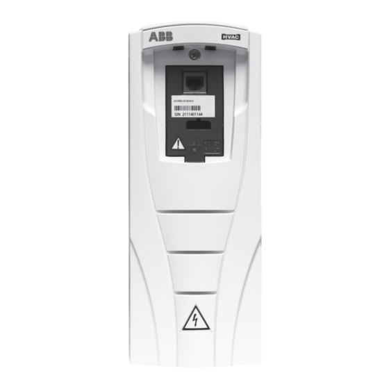
model number (see the unit's nameplate). Use Table 1 to identify whether a given unit is equipped with
the factory-installed VFD option.
NOTE: Read the entire instruction manual before starting the
installation.
CONTENTS
SAFETY CONSIDERATIONS . . . . . . . . . . . . . . . . . . . 1
GENERAL . . . . . . . . . . . . . . . . . . . . . . . . . . . . . . . . . . . 2
Indoor Fan Speed System . . . . . . . . . . . . . . . . . . . 2
Identifying Factory Option . . . . . . . . . . . . . . . . . . . . . 2
Unit Installation with SAV Option . . . . . . . . . . . . . . . 3
Pre-Start Check, SAV™ Option . . . . . . . . . . . . . . . . . 5
START-UP, SAV™ OPTION . . . . . . . . . . . . . . . . . . . 16
Compressor Rotation . . . . . . . . . . . . . . . . . . . . . . . . 16
Indoor Fan Motor . . . . . . . . . . . . . . . . . . . . . . . . . . . . 16
Cooling with SAV . . . . . . . . . . . . . . . . . . . . . . . . . . . 16
Operating Sequences, SAV Option . . . . . . . . . . . . . 16
Cooling (FAN Switch in AUTO) . . . . . . . . . . . . . . . . 16
Heating . . . . . . . . . . . . . . . . . . . . . . . . . . . . . . . . . . . . 16
Operating Fan for Test and Balance . . . . . . . . . . . . 17
SERVICE . . . . . . . . . . . . . . . . . . . . . . . . . . . . . . . . . . 18
SAV™ Option Components . . . . . . . . . . . . . . . . . . . 18
Fan Speed Relay Board . . . . . . . . . . . . . . . . . . . . . . 18
Configuration Jumpers . . . . . . . . . . . . . . . . . . . . . . . 18
Variable Frequency Drive . . . . . . . . . . . . . . . . . . . . . 18
(48/50 Series Only) . . . . . . . . . . . . . . . . . . . . . . . . 20
VFD Fuses . . . . . . . . . . . . . . . . . . . . . . . . . . . . . . . . . 21
Control and Power Wiring Diagrams . . . . . . . . . . . . 22
Alarms . . . . . . . . . . . . . . . . . . . . . . . . . . . . . . . . . . . . 29
Faults . . . . . . . . . . . . . . . . . . . . . . . . . . . . . . . . . . . . . 29
VFD MAINTENANCE . . . . . . . . . . . . . . . . . . . . . . . . . 30
Heat Sink Cleaning . . . . . . . . . . . . . . . . . . . . . . . . . . 30
Fan Replacement . . . . . . . . . . . . . . . . . . . . . . . . . . . 31
Bypass the VFD . . . . . . . . . . . . . . . . . . . . . . . . . . . . . 33
VFD PARAMETERS . . . . . . . . . . . . . . . . . . . . . . . . . . 35
ACH550/580 VFD Common Parameters for 48/50 Units
with I/O Flex Controls . . . . . . . . . . . . . . . . . . . . . . 55
VFD REMOTE KEYPAD . . . . . . . . . . . . . . . . . . . . . . . 63
ACH550/ACS320 VFD Modes . . . . . . . . . . . . . . . . . . 63
ACH550/ACS320 VFD Diagnostics . . . . . . . . . . . . . 65
Correcting Faults . . . . . . . . . . . . . . . . . . . . . . . . . . . 65
Manufacturer reserves the right to discontinue, or change at any time, specifications or designs without notice and without incurring obligations.
Catalog No. 04-53480483-01
Page
Printed in U.S.A.
Form No. VFD-12SI
Variable Frequency Drive (VFD)
Factory-Installed Option
2-Speed Motor Control
for 2-Stage Cooling Rooftop Units
History . . . . . . . . . . . . . . . . . . . . . . . . . . . . . . . . . . . . .65
Reset After Using Start-Up Assistant . . . . . . . . . . .68
ACH580 Operation with Remote Keypad . . . . . . . .69
ACH580 VFD Modes . . . . . . . . . . . . . . . . . . . . . . . . .70
ACH580 VFD Diagnostics . . . . . . . . . . . . . . . . . . . . .72
Control Panel Cleaning . . . . . . . . . . . . . . . . . . . . . . .75
Battery Replacement . . . . . . . . . . . . . . . . . . . . . . . . .75
VFD Remote Keypad Parameters . . . . . . . . . . . . . . .75
SAFETY CONSIDERATIONS
CAUTION
CONFIGURATION OVERRIDE HAZARD
Do not use ABB or Carrier start-up assistant on this VFD
application. Use of start-up assistant will override the factory
VFD configurations.
Improper installation, adjustment, alteration, service, mainte-
nance, or use can cause explosion, fire, electrical shock or other
conditions which may cause personal injury or property damage.
Consult a qualified installer, service agency, or your distributor or
branch for information or assistance. The qualified installer or
agency must use factory-authorized kits or accessories when mod-
ifying this product. Refer to the individual instructions packaged
with the kits or accessories when installing.
Follow all safety codes. Wear safety glasses and work gloves. Use
quenching cloths for brazing operations and have a fire extin-
guisher available. Read these instructions thoroughly and follow
all warnings or cautions attached to the unit. Consult local build-
ing codes and appropriate national electrical codes (in USA,
ANSI/NFPA70, National Electrical Code (NEC); in Canada,
CSA C22.1) for special requirements.
It is important to recognize safety information. This is the safety-
alert symbol
. When you see this symbol on the unit and in in-
structions or manuals, be alert to the potential for personal injury.
Understand the signal words DANGER, WARNING, CAUTION,
and NOTE. These words are used with the safety-alert symbol.
DANGER identifies the most serious hazards which will result in
severe personal injury or death. WARNING signifies hazards
which could result in personal injury or death. CAUTION is used
to identify unsafe practices, which may result in minor personal
injury or product and property damage.
NOTE is used to highlight suggestions which will result in
enhanced installation, reliability, or operation.
Pg 1
1-24
Replaces: VFD-11SI
Advertisement
Table of Contents

Related Manuals for Carrier 48TC 07


Summary of Contents for Carrier 48TC 07
-
Page 1: Table Of Contents
Cooling with SAV ......16 Do not use ABB or Carrier start-up assistant on this VFD Operating Sequences, SAV Option . -
Page 2: General
GENERAL Staged Air Volume (SAV™) Indoor Fan Speed System The Staged Air Volume (SAV) system utilizes a Fan Speed control board and Variable Frequency Drive (VFD) to automatically ad- just the indoor fan motor speed in sequence with the unit’s ventila- tion, cooling and heating operation. -
Page 3: Unit Installation With Sav Option
40RU WITH REMOTE VFD KEYPAD Unit Installation with SAV Option Refer to the base unit installation instructions for standard required 48/50HC, 50HCQ, 48/50TC, AND 50TCQ ROOFTOP operating and service clearances. Install the accessory remote Refer to the base unit installation instructions for standard required VFD keypad before positioning the 40RU unit in its final operat- operating and service clearances. - Page 4 4950 MODEL-SIZE MOTOR (AT MOTOR (AT FAN MOTOR 48HC 28 7500 8450 5577 HIGH SPEED) LOW SPEED) 48TC 07 1800 1800 1188 Table 6 — 50HC Min cfm Per Fan Motor Type 48TC 08 2250 2250 1485 48TC 09 2550...
-
Page 5: Pre-Start Check, Sav™ Option
Pre-Start Check, SAV™ Option Table 10 — 40RUQ Min cfm Per Fan Motor Type Remove the access panel to reach the VFD. 2-SPEED FAN 2-SPEED FAN • 48/50 Series: Blower compartment panel SINGLE SPEED MODEL-SIZE MOTOR (AT MOTOR (AT FAN MOTOR •... - Page 6 Variable Frequency Drive (VFD) Fig. 7 — ACH550/580 VFD Location for the following units: 48/50TC 07 (575V units only) Variable Frequency Drive (VFD) Fig. 8 — ACS320 VFD Location for the following units: 48/50TC 08 (208/230V and 460V units only)
- Page 7 Variable Frequency Drive (VFD) Fig. 9 — ACH550/580 VFD Location for the following units: 48/50TC 08 (575V units only) Variable Frequency Drive (VFD) Fig. 10 — ACH550/580 VFD Location for the following units: 48/50HC 07 and 50HCQ 07...
- Page 8 Variable Frequency Drive (VFD) Fig. 11 — ACS320 VFD Location for the following units: 48/50TC 09-14 and 50TCQ 08-12 (208/230V and 460V units only) Variable Frequency Drive (VFD) Fig. 12 — ACH550/580 VFD Location for the following units: 48/50TC 09-14 and 50TCQ 08-12 (575V units only)
- Page 9 Variable Frequency Drive (VFD) Fig. 13 — ACH550/580 VFD Location for the following units: 48/50HC 08-09 and 50HCQ 08-09 Variable Frequency Drive (VFD) Fig. 14 — ACS320 VFD Location for the following units: 48/50TC 16 and 50TCQ 14 (208/230V and 460V units only)
- Page 10 Variable Frequency Drive (VFD) Fig. 15 — ACH550/580 VFD Location for the following units: 48/50TC 16 and 50TCQ 14 (575V units only) Variable Frequency Drive (VFD) Fig. 16 — ACS320 VFD Location for the following units: 48/50TC 17-30, 50TCQ 17-24 and 48/50HC 17-28 No ComfortLink Controls (208/230V and 460V units only)
- Page 11 Variable Frequency Drive (VFD) Fig. 17 — ACH550/580 VFD Location for the following units: 48/50TC 17-30 and 50TCQ 17-24 (575V units only), 48/50HC 17-28 ComfortLink Controls and 575 Units Variable Frequency Drive (VFD) Fig. 18 — ACS320 VFD Location for the following units: 40RUA/RUQ 07-12, 40RUS 08-12 (208/230V and 460V only)
- Page 12 Variable Frequency Drive (VFD) Fig. 19 — ACS320 VFD Location for the following units: 40RUA/RUS 14-25, 40RUQ 16-25 (208/230V and 460V only) Variable Frequency Drive (VFD) Fig. 20 — ACS320 VFD Location for the following units: 40RUA/RUS 28-30 (208/230V and 460V only)
- Page 13 Variable Frequency Drive (VFD) Fig. 21 — ACH550/580 VFD Location for the following units: 40RUA/RUQ 07-12, 40RUS 08-12 (575V only)
- Page 14 Variable Frequency Drive (VFD) Fig. 22 — ACH550/580 VFD Location for the following units: 40RUA/RUS 14-25, 40RUQ 16-25 (575V only)
- Page 15 Variable Frequency Drive (VFD) Fig. 23 — ACH550/580 VFD Location for the following units: 40RUA/RUS 28-30 (575V only)
-
Page 16: Start-Up, Sav™ Option
50HC, TC SERIES UNITS START-UP, SAV™ OPTION The thermostat’s G terminal is energized with 24-v. This signal Compressor Rotation is conveyed to the 50HC,TC Series unit’s Central Terminal Units equipped with a VFD on the indoor fan motor cannot use ro- Board (CTB) at the field connection TSTAT terminal strip at ter- tation direction of the indoor fan motor and fan to visually confirm minal G. -
Page 17: Operating Fan For Test And Balance
40RU, 50-SERIES At the VFD keypad, tap the HAND key and then tap the UP arrow button to increase the motor speed until 60.0 is Indoor fan motor ramps down to stop. displayed on the display screen. 48-SERIES Check the motor speed with stroboscope or similar tool. The IGC’s fan-off delay sequence will energize relay K3 for Motor shaft speed must be in 1725 to 1760 rpm (28.8 to 45-seconds, causing the VFD to operate the indoor fan motor... -
Page 18: Service
CONFIGURATION OVERRIDE HAZARD See Fig. 28 (on page 19) for a simplified connection schematic for Do not use ABB or Carrier start-up assistant on this VFD Fan Speed Relay board and the VFD. application. Use of start-up assistant will override the factory In this SAV application, there are three inputs to the relay board, VFD configurations. - Page 19 • For ACH550/580 VFDs the voltage is sourced from the air volume during speed changes. It also has internal over cur- VFD at its terminal 10 (+24 V). SAV speed inputs are re- rent protection for the fan motor. ceived at terminals 14 (DI-2) for low speed (40 Hz) motor INDOOR FAN MOTOR operation and 15 (DI-3) for high speed (60 Hz) motor op- eration.
-
Page 20: Central Terminal Board Jumpers
The CTB contains no software and no logic. But it does include Table 12 — ACS320 VFD Terminal Designations seven configuration jumpers that are cut to configure the board to TERMINAL FUNCTION read external optional and accessory controls, including that the U1... -
Page 21: Vfd Fuses
VFD Fuses Table 16 details the fuse requirement for the VFD installed in the control wiring diagram label on the specific unit in use for the 48/50TC, 50TCQ, 48/50HC, and 50HCQ units. Table 17 details fuse location. the fuse requirement for the VFD installed in 40RU units. Check Table 16 —... -
Page 22: Control And Power Wiring Diagrams
Table 17 — VFD Fuse Requirements, 40RU Units HARNESS UNIT VOLTAGE (ASC320 / ACH550 / MOTOR STANDARDIZED FUSE FUSE P/N WIRE ACH580) GAUGE 208/230 HK30WA523 HD56FR233 30A - CLASS CC KTK HY10KB300 HK30WA530 HD56FR463 15A - CLASS CC KTK HY10KB151 HK30WA360 (550) HD56FR579 10A - CLASS CC KTK... - Page 23 Fig. 32 — Typical Wiring Diagram - Single Package Rooftop Unit (48TC*07 with ACS320 VFD shown)
- Page 24 Fig. 33 — Typical Wiring Diagram - Single Package Rooftop Unit (50TC*07 with ACS320 VFD shown)
- Page 25 Fig. 34 — Typical Wiring Diagram - Single Package Rooftop Unit (48HC*14 with ACH550/ACH580 VFD shown)
- Page 26 Fig. 35 — Typical Wiring Diagram - Single Package Rooftop Unit (50HC*14 with ACH550/ACH580 VFD shown)
- Page 27 Fig. 36 — Typical Wiring Diagram - Single Package Rooftop Unit (48TC*17-30 and 48HC*17-28 no Comfort Link with ACS320 VFD shown)
- Page 28 Fig. 37 — Typical Wiring Diagram - Single Package Rooftop Unit (50TC*17-30 and 50HC*17-28 no Comfort Link with ACS320 VFD shown)
-
Page 29: Vfd Alarms And Faults Troubleshooting
Fig. 38 — Typical Wiring Diagram - Split System Air-Handling Unit (40RU with ACH550/ACH580 VFD shown) CLEAR THE ALARM LED VFD ALARMS AND FAULTS TROUBLESHOOTING Shut off power to the VFD for five minutes. Restore power and The VFD has two LEDs ACH550/ACS320 or only one LED recheck the GREEN LED. -
Page 30: Vfd Maintenance
VFD MAINTENANCE If installed in an appropriate environment, the VFD requires very little maintenance. Table 18 lists the routine maintenance intervals recommended by Carrier. Table 18 — Maintenance Intervals MAINTENANCE INTERVAL Every 6 to 12 months Heat sink temperature check ... -
Page 31: Fan Replacement
If the drive is operated in a critical part of a process, fan replacement is recommended once these symptoms start appearing. Replacement fans are available from Carrier. ACH580 MAIN FAN REPLACEMENT Fig. 44 — Remove Main Fan... - Page 32 Fig. 45 — Open Keypad Cover and Remove Keypad Fig. 47 — Remove Auxiliary Fan ACH550 FAN REPLACEMENT To replace the fan perform the following Remove power from drive. Wait for 5 minutes and then make sure by measuring that there is no voltage Remove drive cover (see See Fig.
-
Page 33: Bypass The Vfd
ACS320 FAN REPLACEMENT Install the new fan in reverse order. Restore power. To replace the fan perform the following: Remove power from drive. Wait for 5 minutes and then make Bypass the VFD sure by measuring that there is no voltage Insert a small straight blade screwdriver into the slot and press in to release the top cover as shown in See Fig. - Page 34 Unit with Fuse and VFD Control Indoor Fuse Motor Ground Unit without VFD Fan Deck Control Indoor Fuse Motor Ground Fan Deck NOTE(S): Standard fuses need to be replaced with Slow Blow fuses for bypass. Fig. 51 — To Bypass ACS320 VFD on Fused Units — 48/50TC 07-14, 50TCQ 07-12, 48/50HC 07-12, 50HCQ 08-09 and 40RU Units Unit with VFD Control...
-
Page 35: Vfd Parameters
• Table 26 — ACS320 Parameters for 40RU units with VFD PARAMETERS I/O Flex controls The parameters for the VFDs are listed in the following tables • Table 27 — ACH550/580 VFD common parameters for • Table 19 — ACS320 VFD common parameters for 48/50 48/50 units with electromechanical controls units with electromechanical controls •... - Page 36 Table 20 — ACS320 VFD Parameters, for 48/50 Units with Electromechanical Controls VFD PARAMETERS PKG ABB ACS320 MOTOR PART NUMBER VFD PART NUMBER DRIVE HP DESC 48TM003773-DATA 48TM003773 HD56FR233 HK30WA523 SRT 1.7 HP 230V 48TM003776-DATA 48TM003776 HD56FR463 HK30WA530 SRT 1.7 HP 460V 48TM003772-DATA 48TM003772 HD56FE653...
- Page 37 Table 20 — ACS320 VFD Parameters, for 48/50 Units with Electromechanical Controls (cont) LOOKUP VARIABLE VOLTAGE N. AMPS N. RPM N. HP MAX AMPS CROSS REFERENCE VFD PARAMETERS 9905 9906 9908 9909 2003 EM_PKG CL_PKG 48TM003773-DATA 1725 48TM482532 48TM482683 48TM003776-DATA 1725 48TM482535 48TM482686...
- Page 38 Table 21 — ACS320 VFD Common Parameters for 48/50 Units with I/O Flex Controls PARAMETERS DESCRIPTION SETTING ACH550 9907 Motor Nominal Frequency 60Hz 1204 Const Speed 3 60Hz 1403 Relay Output 3 — 1611 Parameter View 2007 Minimum Frequency 2008 Maximum Frequency 60HZ 2101...
- Page 39 Table 22 — ACS320 VFD Parameters, for 48/50 Units with I/O Flex Controls VFD PARAMETERS PKG ABB ACS320 MOTOR PART NUMBER VFD PART NUMBER DRIVE HP DESC 48LC000507-DATA 48LC000507 HD56FR233 HK30WA504 SRT 1.7 HP 230V 48LC000508-DATA 48LC000508 HD56FR463 HK30WA512 SRT 1.7 HP 460V 48LC000511-DATA 48LC000511 HD56FE653...
- Page 40 Table 22 — ACS320 VFD Parameters, for 48/50 Units with I/O Flex Controls (cont) EXT1 EXT1/EXT2 REF1 CONST CONST CONST LOOKUP VARIABLE VOLTAGE N. AMPS N. RPM N. HP COMMANDS SELECT SPEED SEL SPEED 1 SPEED 2 VFD PARAMETERS 9905 9906 9908 9909...
- Page 41 Table 22 — ACS320 VFD Parameters, for 48/50 Units with I/O Flex Controls (cont) CONST CONST STOP BAUD LOOKUP VARIABLE AO1 Content Sel ACCEL DECEL STATION ID PARITY SPEED 3 SPEED 4 AMPS RATE VFD PARAMETERS 1204 1205 1501 2003 2102 2202 2203...
- Page 42 Table 22 — ACS320 VFD Parameters, for 48/50 Units with I/O Flex Controls (cont) EFB STATION EFB BAUD COMM PROT LOOKUP VARIABLE EFB PARITY RUN ENABLE CROSS REFERENCE RATE VFD PARAMETERS 5302 5303 5304 9802 1601 1608 EM_PKG CL_PKG 48LC000507-DATA 76.8kb/s 8 NONE 1 BACnet...
- Page 43 Table 22 — ACS320 VFD Parameters, for 48/50 Units with I/O Flex Controls (cont) VFD PARAMETERS PKG ABB ACS320 MOTOR PART NUMBER VFD PART NUMBER DRIVE HP DESC 48LC000604-DATA 48LC000604 HD60FK658 HK30WA506 MRT 5.25 HP 230V 48LC000605-DATA 48LC000605 HD60FK658 HK30WA513 MRT 5.25 HP 460V 48LC000607-DATA 48LC000607...
- Page 44 Table 22 — ACS320 VFD Parameters, for 48/50 Units with I/O Flex Controls (cont) EXT1 EXT1/EXT2 REF1 CONST CONST CONST LOOKUP VARIABLE VOLTAGE N. AMPS N. RPM N. HP COMMANDS SELECT SPEED SEL SPEED 1 SPEED 2 VFD PARAMETERS 9905 9906 9908 9909...
- Page 45 Table 22 — ACS320 VFD Parameters, for 48/50 Units with I/O Flex Controls (cont) CONST CONST STOP BAUD LOOKUP VARIABLE AO1 Content Sel ACCEL DECEL STATION ID PARITY SPEED 3 SPEED 4 AMPS RATE VFD PARAMETERS 1204 1205 1501 2003 2102 2202 2203...
- Page 46 Table 22 — ACS320 VFD Parameters, for 48/50 Units with I/O Flex Controls (cont) EFB STATION EFB BAUD COMM PROT LOOKUP VARIABLE EFB PARITY RUN ENABLE CROSS REFERENCE RATE VFD PARAMETERS 5302 5303 5304 9802 1601 1608 EM_PKG CL_PKG 48LC000604-DATA 76.8kb/s 8 NONE 1 BACnet...
- Page 47 Table 22 — ACS320 VFD Parameters, for 48/50 Units with I/O Flex Controls (cont) VFD PARAMETERS PKG ABB ACS320 MOTOR PART NUMBER VFD PART NUMBER DRIVE HP DESC 48TM005433-DATA 48TM005433 HD56FR233 HK30WA506 SRT 3 HP 230 V 48TM005436-DATA 48TM005436 HD56FR463 HK30WA512 SRT 3 HP 460 V 48TM005439-DATA...
- Page 48 Table 22 — ACS320 VFD Parameters, for 48/50 Units with I/O Flex Controls (cont) EFB STATION EFB BAUD COMM PROT LOOKUP VARIABLE EFB PARITY RUN ENABLE CROSS REFERENCE RATE VFD PARAMETERS 5302 5303 5304 9802 1601 1608 EM_PKG CL_PKG 48TM005433-DATA —...
- Page 49 Table 23 — ACS320 VFD Common Parameters for 40RU Units with Electromechanical Controls PARAMETERS DESCRIPTION SETTING ACS320 9802 COMM PROT Sel — 9907 Motor Nominal Frequency 60Hz 1001 EXT1 Commands — 1102 EXT1/EXT2 Sel — 1103 REF 1 Select — 1201 Const Speed Sel DI 2,3...
- Page 50 Table 24 — ACS320 VFD Parameters, for 40RU Units with Electromechanical Controls VFD PARAMETERS PKG ABB ACS320 MOTOR PART NUMBER VFD PART NUMBER DRIVE HP DESC 40RU000130-DATA 40RU000130 HD56FR233 HK30WA523 40RU 1.7 HP 230V 40RU000131-DATA 40RU000131 HD56FR463 HK30WA530 40RU 1.7 HP 460V 40RU480011-DATA 40RU480011 HD56FE653...
- Page 51 Table 25 — ACS320 VFD Common Parameters for 40RU Units with I/O Flex Controls PARAMETERS DESCRIPTION SETTING ACS320 9802 COMM PROT Sel BACnet 9907 Motor Nominal Frequency 60Hz 9908 N. RPM 1725 1001 EXT1 Commands (1) DI1 1102 EXT1/EXT2 Sel EXT1 1103 REF 1 Select...
- Page 52 Table 26 — ACS320 VFD Parameters, for 40RU Units with I/O Flex Controls VFD PARAMETERS PKG ABB ACS320 MOTOR PART NUMBER VFD PART NUMBER DRIVE HP DESC 40RU000203-DATA 40RU000203 HD56FR233 HK30WA523 40RU 1.7 HP 230V 40RU000204-DATA 40RU000204 HD56FR463 HK30WA530 40RU 1.7 HP 460V 40RU000218-DATA 40RU000218 HD56FE653...
- Page 53 Table 27 — ACH550/580 VFD Common Parameters for 48/50 Units with Electromechanical Controls PARAMETERS ACH550 / 580 DESCRIPTION SETTING ACH550 | ACH580 9802 / 58.01 COMM PROT Sel — 9907 / 99.08 Motor Nominal Frequency 60Hz 1001 / 20.01 EXT1 Commands —...
- Page 54 Table 28 — ACH550/580 VFD Parameters, for 48/50 Units with Electromechanical Controls MOTOR DRIVE VFD PARAMETERS PKG ABB ACH550 PART NUMBER DESC PART NUMBER ACH550 / ACH580 48TM482532-DATA 48TM482532 HD56FR233 HK30WA352 / HK30WB304 SRT 1.7 HP 230V 48TM482535-DATA 48TM482535 HD56FR463 HK30WA356 / HK30WB319 SRT 1.7 HP 460V 48TM482538-DATA...
-
Page 55: With I/O Flex Controls
1745 50HE003094-DATA 1750 10.4 48TM005169-DATA 1725 48TM005161-DATA 1725 48TM005170-DATA 1725 50TM001601-DATA 1725 50TM001205-DATA 1725 50TM001207-DATA 1745 ACH550/580 VFD Common Parameters for 48/50 Units with I/O Flex Controls Please contact your Carrier National Accounts representative for all I/O Flex ACH580 questions. - Page 56 Table 29 — ACH550/580 VFD Parameters — 40RU/40RUQ Unit VFD Parameters for Units with VFD Fan Speed Relay Board — 40RUA 07-30, 40RUS 08-30 and 40RUQ 07-25 550 / 580 550 / 580 NOM 550 / 580 550 / 580 550/580 VFD PART 550/580 ABB PART MOTOR PART...
- Page 57 Table 29 — ACH550/580 VFD Parameters — 40RU/40RUQ Unit VFD Parameters for Units with VFD Fan Speed Relay Board — 40RUA 07-30, 40RUS 08-30 and 40RUQ 07-25 (cont) 550 / 580 550 / 580 550 / 580 550 / 580 550 / 580 550 / 580 550/580 VFD PART...
- Page 58 Table 29 — ACH550/580 VFD Parameters — 40RU/40RUQ Unit VFD Parameters for Units with VFD Fan Speed Relay Board — 40RUA 07-30, 40RUS 08-30 and 40RUQ 07-25 (cont) 550 / 580 550 / 580 550 / 580 550 / 580 550 / 580 550 / 580 550 / 580...
- Page 59 Table 30 — ACH550/580 VFD Parameters, for 40RU Units with I/O Flex Controls VFD PARAMETERS VFD PART NUMBER PKG ABB ACH550 MOTOR PART NUMBER DRIVE HP DESC (ACH550 / ACH580) (ACH550 / ACH580) 40RU000205-DATA / HK30WA360 / 40RU000205 HD56FR579 40RU 1.7 HP 575V 40RU000606-DATA HK30WB340 40RU000220-DATA /...
- Page 60 Table 31 — ACH550/580 VFD Common Parameters for 48/50 Units with ComfortLink Controls PARAMETERS SETTING DESCRIPTION ACH550/580 ACH550/580 9802 / 58.01 COMM PROT SEL 6 LEN / 8 LEN 9907 / 99.08 Motor Nominal Frequency 60Hz 1001 / 20.01 EXT1 Commands —...
- Page 61 Table 32 — ACH550/580 VFD Parameters, for 48/50 Units with ComfortLink Controls VFD PART NUMBER VFD PARAMETERS PKG ABB ACH550 MOTOR PART NUMBER DRIVE HP DESC (ACH550 / ACH580) 48TM482683-DATA 48TM482683 HD56FR233 HK30WA352 / HK30WB304 SRT 1.7 HP 230V 48TM482686-DATA 48TM482686 HD56FR463 HK30WA356 / HK30WB319...
- Page 62 Table 32 — ACH550/580 VFD Parameters, for 48/50 Units with ComfortLink Controls (cont) LOOKUP VARIABLE VOLTAGE N. AMPS N. RPM N. HP MAX AMPS CROSS REFERENCE VFD PARAMETERS 9905 / 99.07 9906 / 99.06 9908 / 99.09 9909 / 99.10 2003 / 30.17 EM_PKG CL_PKG...
-
Page 63: Vfd Remote Keypad
CONFIGURATION OVERRIDE HAZARD is local from the control panel. The AUTO icon indicates that the Do not use ABB or Carrier start-up assistant on this VFD drive is in remote control mode, such as the basic I/O or field bus. - Page 64 (SOFT KEY 1). DOWN keys simultaneously. To restore the default factory set- When the download is complete, the text “Parameter tings, select the Carrier application macro. download successful” will be displayed. CHANGED PARAMETERS MODE The display will then return to the PAR BACKUP menu.
-
Page 65: Ach550/Acs320 Vfd Diagnostics
The text “Downloading Parameters (partial)” will be dis- ACH550/ACS320 VFD Diagnostics played with a progress indicator. To stop the process, The drive detects error situations and reports them using: select ABORT (SOFT KEY 1). • Green and red LEDs on the body of the drive (located un- When the download is complete, the text “Parameter der the keypad) download successful”... - Page 66 3015 UNDERLOAD CURVE. THERM FAIL Internal fault. The thermistor measuring the internal temperature of the drive is open or shorted. Contact Carrier. OPEX LINK Internal fault. A communication-related problem has been detected between the OMIO and OINT boards. Contact Carrier.
- Page 67 Table 33 — ACH550/ACS320 Fault Codes (cont) FAULT FAULT NAME IN PANEL DESCRIPTION AND RECOMMENDED CORRECTIVE ACTION CODE Parameter values are inconsistent. Check that parameter 1301 AI 1 MIN > 1302 AI 1 MAX and that parameter 1304 AI 2 1003 PAR AI SCALE MIN >...
-
Page 68: Reset After Using Start-Up Assistant
Disconnect the DI1 input at Terminal 13 (see Fig. 56 for CONFIGURATION OVERRIDE HAZARD location of DI1). Do not use ABB or Carrier start-up assistant on this VFD Connect the VFD Keypad accessory to the VFD (if not application. Use of start-up assistant will override the factory already connected). -
Page 69: Ach580 Operation With Remote Keypad
CONFIGURATION OVERRIDE HAZARD matches the word in the lower left-hand box on the display screen. Do not use ABB or Carrier start-up assistant on this VFD The function of Right Softkey matches the word in the lower application. Use of start-up assistant will override the factory right-hand box on the display screen. -
Page 70: Ach580 Vfd Modes
START UP BY CHANGING PARAMETERS The first time the drive is powered up, it is in the OFF mode. To switch to local hand-held control and control the drive using the INDIVIDUALLY control panel, press and hold the HAND button. Pressing the Initial start-up is performed at the factory. - Page 71 Use the UP or DOWN keys to highlight the desired Upload All Parameters parameter group and press Select (Press To upload and store parameters in the control panel from the VFD insert the Keypad into the VFD slot (Fig. 61) and animation will Use the UP or DOWN keys to highlight the desired appear loading the VFD configuration.
-
Page 72: Ach580 Vfd Diagnostics
If diagnostics troubleshooting has determined that the drive is de- Use the UP or DOWN keys to select the parameter to view. fective during the warranty period, contact Carrier. Press OK (Press Use the UP or DOWN keys to change the parameter setting. - Page 73 Hardware manual of the drive. If an earth fault is found, fix or change the motor cable and/or motor. If no earth fault can be detected, contact your local Carrier representative. Check motor and motor cable for cabling errors.
- Page 74 Table 35 — Fault and Alarm Codes for ACH580 VFD (cont) CODE (HEX) WARNING / AUX. CODE CAUSE WHAT TO DO The start delay is active and the Check that it is safe to continue operation. Then return AFE9 Start delay drive will start the motor after a emergency stop push button to normal position.
-
Page 75: All Ach580, Ach550 And Ach320 Keypads
operating in memory during power interruptions. The expected ALL ACH580, ACH550 AND ACH320 KEYPADS life for the battery is greater than ten years. To remove the battery, Control Panel Cleaning use a coin to rotate the battery holder on the back of the control panel. - Page 76 Table 37 — ACH550/580 VFD Parameters — 48/50TC 16, 50TCQ 14, 48/50HC 14 and 50HCQ 12 Motor Const Const Const Const Const ACH550 ACH580 Voltage Speed Speed Speed Speed Speed VFD Part Replacement Replacement Motor Part Amps Description 9905 Freq Number Component Component...
- Page 77 Table 38 — ACH550/580 VFD Parameters — 48/50TC17-30, 50TCQ 17-24 and 48/50HC 17-28 Motor Const Const Const Const Const ACH550 ACH580 Voltage Speed Speed Speed Speed Speed VFD Part Replacement Replacement Motor Part Amps Description 9905 Freq Number Component Component Number 9906 9908...
- Page 78 Table 38 — ACH550/580 VFD Parameters — 48/50TC17-30, 50TCQ 17-24 and 48/50HC 17-28 (cont) ACH550 ACH580 Switch Stop Accel/ Relay Out 3 Start Fcn Accel Decel VFD Part Replacement Replacement Amps Freq Freq Freq Decel Description 1403 2101 2202 2203 Number Component Component...
- Page 79 Table 39 — ACH550/580 VFD Parameters — 40RUA 07-30, 40RUS 08-30 and 40RUQ 07-25 Motor Const Const Const Const Const ACH550 ACH580 Volt Speed Speed Speed Speed Speed VFD Part Replacement Replacement Motor Part Amps Description (9905/ Freq Number Component Component Number (9906/...
- Page 80 Table 40 — ACS320 VFD Parameters — 48/50TC07-16 and 50TCQ07-14 (208/230V and 460V units only) Motor Const Const Const Const Replacement VFD Part Motor Part Volt Speed Speed Speed Speed Component Description Amps Number Number (9905) Freq Part Number (9906) (9908) (9909) (9907)
- Page 81 Table 41 — ACS320 VFD Parameters — 48/50TC17-30 and 50TCQ17-24 (208/230V and 460V units only) Const Const Const Replacement Motor Const VFD Part Motor Part Volt Speed Speed Speed Component Description Amps Nom Freq Speed Number Number (9905) Part Number (9906) (9907) (9908)
- Page 82 Table 42 — ACS320 VFD Parameters — 40RU (208/230V and 460V units only) Motor Const Const Const Const Replacement VFD Part Motor Part Volt Speed Speed Speed Speed Component Part Description Amps Number Number (9905) Freq Number (9906) (9908) (9909) (9907) (1201) (1202)
- Page 84 © 2024 Carrier Manufacturer reserves the right to discontinue, or change at any time, specifications or designs without notice and without incurring obligations. Catalog No. 04-53480483-01 Printed in U.S.A. Form No. VFD-12SI Pg 84 1-24 Replaces: VFD-11SI...
Need help?
Do you have a question about the 48TC 07 and is the answer not in the manual?
Questions and answers