GENTILIN C 330/24 Instruction Manual
Hide thumbs
Also See for C 330/24:
- Instruction manual (37 pages) ,
- Operating instructions manual (17 pages)
Table of Contents
Advertisement
Available languages
Available languages
Quick Links
Advertisement
Table of Contents

Related Manuals for GENTILIN C 330/24


Summary of Contents for GENTILIN C 330/24
- Page 1 MANUALE USO E MANUTENZIONE INSTRUCTION MANUAL mod. C 330/03 - C 330/24 - C 330/50 istruzioni originali translation of the original instructions GENTILIN SRL Via delle Tezze, 20/22 | 36070 Trissino (VI) ITALY Tel. +39 0445 962000 | info@gentilincompressors.com...
- Page 2 IL PRESENTE MANUALE è REDATTO IN DUE LINGUE (ITALIANO/INGLESE). I MANUALI IN LINGUE DIVERSE SONO DISPONIBILI NELL’AREA ASSISTENZA DEL SITO WEB: www.gentilincompressors.com THIS MANUAL IS DRAWN UP IN TWO LANGUAGES (ITALIAN/ENGLISH). THE MANUALS IN DIFFERENT LANGUAGES ARE AVAILABLE IN THE SUPPORT AREA OF THE WEBSITE: www.gentilincompressors.com DIESE ANLEITUNG IST IN ZWEI SPRACHEN VERFASST (ITALIENISCH/ENGLISCH).
-
Page 3: Table Of Contents
Rev. 01_05_2017 MAN_C330_A001 I TA L I A N O INDICE 1 DENOMINAZIONE DEI COMPONENTI ....................4 2 DATI TECNICI ............................5 3 DICHIARAZIONE CE DI CONFORMITÀ ....................5 4 MARCATURA CE ............................6 5 IMPORTANZA DEL MANUALE ........................ 6 6 DESTINATARI ............................ -
Page 4: Denominazione Dei Componenti
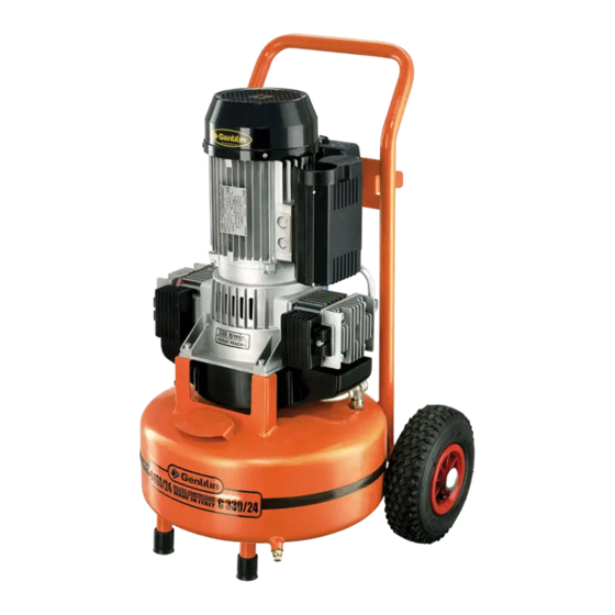
MAN_C330_A001 Rev. 01_05_2017 1. DENOMINAZIONE DEI COMPONENTI Valvola di non ritorno Filtro aspirazione aria Ruote Valvola di sicurezza (tarata a 10,5 bar) Valvola di scarico condensa Manometro pressione serbatoio Manometro pressione in uscita Pressostato Serbatoio aria Interruttore ON (I) - OFF (0) Motore elettrico Termico ripristinabile Regolatore di pressione in uscita... -
Page 5: Dati Tecnici
Il compressore può essere utilizzato in entrambi i sensi di rotazione 3. DICHIARAZIONE CE DI CONFORMITÀ Gentilin S.r.l. - Via delle Tezze, 20/22 36070 Trissino (VI) - Italy - P. IVA/Codice Fiscale: 01262520248 Dichiara che le seguenti macchine: COMPRESSORI C330/03 - C330/24 - C330/50... -
Page 6: Marcatura Ce
MAN_C330_A001 Rev. 01_05_2017 4. MARCATURA CE La marcatura CE attesta la conformità della macchina ai requisiti essenziali di sicurezza e di salute previsti dalla Direttiva Macchine 2006/42/CE. È costituita da una targhetta adesiva in poliestere, con stampa a trasferimento termico di colore nero ed è... -
Page 7: Stato "Macchina Spenta
Rev. 01_05_2017 MAN_C330_A001 GLI OPERATORI AUTORIZZATI PRIMA DI ESEGUIRE QUALSIASI INTERVENTO SULLA MACCHINA DEVONO ASSICURARSI DI ESSERE IN POSSESSO DELLE PIENE FACOLTÀ PSICO-FISICHE TALI DA GARANTIRE SEMPRE IL RISPETTO DELLE CONDIZIONI DI SICUREZZA. OPERATORE ADDETTO: È un operatore che ha compiuto il 18° anno di età (utente privato o lavorato- re) e che, conformemente a quanto previsto dalla legislazione vigente nel paese di utilizzazione in materia di sicurezza e salute nei luoghi di lavoro, sia in grado di eseguire esclusivamente l’accensione, l’utilizzo e lo spegnimento della macchina nel rispetto assoluto delle istruzioni qui riportate, dotato dei dispositivi di... -
Page 8: Garanzia
MAN_C330_A001 Rev. 01_05_2017 8. GARANZIA 1) DICHIARAZIONE DI GARANZIA: il fabbricante si impegna nei confronti dell’acquirente di sostituire, riparare o in- tervenire altrimenti sulla macchina, qualora essa presenti dei difetti di conformità che ne compromettano il corretto uso e funzionamento, esclusivamente se tali difetti sono riconducibili alla effettiva responsabilità del fabbricante. Il fabbricante si riserverà... -
Page 9: Uso Scorretto Ragionevolmente Prevedibile
Rev. 01_05_2017 MAN_C330_A001 USO PREVISTO Compressione dell’aria (senza olio) per l’utilizzo di utensili pneumatici idonei e conformi alle normative vigenti (esempio pistole per soffiaggio, gonfiaggio, lavaggio, verniciatura o sabbiatura, ecc.). OPERATORI ADDETTI ALL’UTILIZZO Un operatore autorizzato in possesso dei requisiti tecnico professionali descritti al paragrafo 6. 11. -
Page 10: Trasporto E Movimentazione Della Macchina
MAN_C330_A001 Rev. 01_05_2017 12. TRASPORTO E MOVIMENTAZIONE DELLA MACCHINA La macchina può essere trasportata manualmente da due operatori addetti impugnandola per il piedino (A) e per la maniglia (B) o movimentata manualmente da un operatore addetto tramite la maniglia (C) e le ruote (D) di cui è dotata. IL TRASPORTO DELLA MACCHINA DEVE ESSERE OBBLIGATORIAMENTE ESEGUITO DA DUE OPERATORI AD- DETTI NEL RISPETTO DELLE NORMATIVE SULLA “MOVIMENTAZIONE MANUALE DEI CARICHI”... -
Page 11: Collegamento Elettrico
Rev. 01_05_2017 MAN_C330_A001 17. COLLEGAMENTO ELETTRICO La macchina può essere collegata alla rete di alimentazione elettrica inserendo la spina del cavo di alimentazione elettrica nell’apposita presa. LA RETE DI ALIMENTAZIONE ELETTRICA A CUI VIENE COLLEGATA LA MACCHINA DEVE ESSERE CONFORME AI REQUISITI PREVISTI ALLA LEGISLAZIONE VIGENTE NEL PAESE DI UTILIZZAZIONE, SODDISFARE LE CA- RATTERISTICHE TECNICHE RIPORTATE NEL PARAGRAFO 2 ED ESSERE DOTATA DI UN IDONEO IMPIANTO DI “MESSA A TERRA”. -
Page 12: Dispositivi Di Sicurezza Adottati
MAN_C330_A001 Rev. 01_05_2017 19. DISPOSITIVI DI SICUREZZA ADOTTATI 1) VALVOLA DI SICUREZZA (4): è una valvola di sicurezza certifi- cata (tarata a 10,5 bar), installata sull’impianto pneumatico sotto al pressostato. Serve a scaricare la sovrappressione dell’impianto qualora il pressostato, per eventuali anomalie, non funzioni. L’intervento della valvola di sicurezza obbliga l’operatore a spegnere la macchina e richiedere l’intervento dei manutentori. -
Page 13: Segnaletica Di Sicurezza
Rev. 01_05_2017 MAN_C330_A001 20. SEGNALETICA DI SICUREZZA La segnaletica di sicurezza impiegata è costituita da una etichetta adesiva, applicata esternamente alla macchina. Significato dei segnali: Pericolo corrente elettrica. Pericolo avvio automatico. Pericolo temperatura elevata. Obbligo leggere istruzioni. Obbligo togliere tensione. Obbligo proteggere l’udito. -
Page 14: Rischi Residui
MAN_C330_A001 Rev. 01_05_2017 22. RISCHI RESIDUI Si informano gli operatori autorizzati che nonostante il fabbricante abbia adottato tutti gli accorgimenti tecnico costruttivi possibili per rendere la macchina sicura, permane un potenziale rischio residuo. RISCHIO RESIDUO Pericolo di scottature per contatto accidentale con gruppo pompante bici- lindrico e motore elettrico. -
Page 15: Controlli Prima Dell'accensione
Rev. 01_05_2017 MAN_C330_A001 25. CONTROLLI PRIMA DELL’ACCENSIONE PRIMA DI EFFETTUARE L’ACCENSIONE DELLA MACCHINA GLI OPERATORI AUTORIZZATI DEVONO OBBLI- GATORIAMENTE ESEGUIRE I CONTROLLI RIPORTATI DI SEGUITO. • Assicurarsi che non vi siano persone non autorizzate nelle vicinanze della macchina. • Assicurarsi che i dispositivi di sicurezza siano integri e correttamente installati e funzionanti (vedi parafrafo 19). • Assicurarsi che la macchina sia correttamente posizionata (vedi parafrafo 15). -
Page 16: Spegnimento Della Macchina
MAN_C330_A001 Rev. 01_05_2017 1) Collegare la macchina alla rete di alimentazio- ne elettrica (1) inserendo la spina del cavo di alimentazione elettrica nell’apposita presa. 2) Accendere la macchina tramite l’interruttore “ON-OFF” (3) in pos. “ON (I)” (la macchina funziona fino a raggiungere la pressione max. di esercizio di 10 bar dopodiché... -
Page 17: Reset Intervento Termico Ripristinabile
Rev. 01_05_2017 MAN_C330_A001 28. RESET INTERVENTO TERMICO RIPRISTINABILE Qualora si verifichi un sovraccarico di corrente e/o un cortocircuito nell’impianto elettrico della macchina, il termico ripristinabile interverrà arrestando il motore elettrico. Per effettuare il reset, procedere come segue: 1) Portare l’interruttore “ON-OFF” (3) in posizione “OFF” (0). 2) Premere il pulsante del termico ripristinabile (B). - Page 18 MAN_C330_A001 Rev. 01_05_2017 TABELLA MANUTENZIONE ORDINARIA FREQUENZA PUNTO DI INTERVENTO TIPO DI INTERVENTO OGNI GIORNO Dispositivi di sicurezza. Assicurarsi che siano integri, correttamente installati e funzio- nanti. Cavo e spina di alimentazione Controllo visivo dello stato di usura. elettrica. Serbatoio. Ad ogni fine ciclo di lavoro appoggiare la macchina a terra e scaricare la condensa dal serbatoio aprendo la valvola di scarico condensa (A).
-
Page 19: Manutenzione Straordinaria
Rev. 01_05_2017 MAN_C330_A001 32. MANUTENZIONE STRAORDINARIA È l’insieme delle attività svolte atte a mantenere le condizioni d’uso e funzionamento della macchina, attraverso vari tipi di intervento (regolazioni, sostituzioni ecc.) eseguiti esclusivamente dai tecnici del fabbricante alla frequenza stabilita o in caso di guasto od usura. PER QUALSIASI INTERVENTO DI MANUTENZIONE STRAORDINARIA RICHIEDERE OBBLIGATORIAMENTE L’ASSISTENZA TECNICA AL FABBRICANTE O AL RIVENDITORE AUTORIZZATO. - Page 20 MAN_C330_A001 Rev. 01_05_2017 ANOMALIE CAUSE RIMEDI La macchina si riavvia Perdite dal tubo aria, dall’u- • Controllare che l’impianto pneumatico non abbia subito più volte senza utilizza- tensile o dall’impianto danni. re l’utensile. pneumatico. • Controllare l’integrità e i collegamenti del tubo aria e dell’u- tensile.
- Page 21 C 330/03 - C 330/24 - C 330/50 ENGLISH GENTILIN SRL Via delle Tezze, 20/22 | 36070 Trissino (VI) ITALY Tel. +39 0445 962000 | info@gentilincompressors.com...
- Page 23 Rev. 01_05_2017 MAN_C330_A001 E N G L I S H INDEx 1 PARTS LIST ............................... 4 2 TECHNICAL SPECIFICATIONS ......................... 5 3 CE DECLARATION OF CONFORMITY ..................... 5 4 CE LABEL ..............................6 5 IMPORTANCE OF THE MANUAL ......................6 6 RECIPIENTS ..............................
- Page 24 MAN_C330_A001 Rev. 01_05_2017 1. PARTS LIST Non-return valve Air filter Wheel Safety valve (set to 10.5 bar) Condensate pump Tank pressure gauge Tank outlet gauge Pressure switch Air tank ON (I) – OFF (O) switch Electric motor Thermal restore Outlet pressure regulator Air outlet spigot Pump/Tank connection pipes Support feet...
- Page 25 The compressor can be used in both directions of rotation 3. CE DECLARATION OF CONFORMITY Gentilin S.r.l. - Via delle Tezze, 20/22 36070 Trissino (VI) - Italy - VAT N.: 01262520248 Declares that the following machine: COMPRESSOR C330/03 - C330/24 - C330/50...
- Page 26 MAN_C330_A001 Rev. 01_05_2017 4. CE LABEL The CE label serves as evidence of the appliance’s compliance with essential health and safety requirements as specified by the Machinery Directive 2006/42/CE. It takes the formof a polyester sticker, with a black thermal transfermould, which are applied on themotor frame. Back view Right side 5.
- Page 27 Rev. 01_05_2017 MAN_C330_A001 AUTHORISED OPERATORS MUST ONLY CARRY OUT OPERATIONS FOR WHICH THEY ARE QUALIFIED. BEFORE CARRYING OUT ANY OPERATIONS, AUTHORISED OPERATORS MUST POSSESS ADEQUATE PSHY- CHO-PHYSICAL CAPABILITES IN ORDER TO ALWAYS ENSURE SAFETY. ASSIGNED OPERATOR: An operator over the age of 18 (private user or employee) and, who, in com- pliance with current legislation on health and safety in the work place in force within the country of usage, is capable of exclusively activating, using and deactivating the appliance whilst completely complying with the instructions presently provided, whilst using the dedicated personal safety device items.
- Page 28 MAN_C330_A001 Rev. 01_05_2017 8. WARRANTY 1) WARRANTY DECLARATION: the Manufacturer guarantees the Acquirer, the replacement, repair and intervention relative to all appliances, where the aforementioned display conformity defects which comprise correct usage and operation, only where such defects are owing to the fault of the Manufacturer. The Manufacturer reserves the right to adopt the best solution in order to restore appliance conformity within a reasonable amount of time.
- Page 29 Rev. 01_05_2017 MAN_C330_A001 INTENDED USE Compressing air (no oil) to be used with suitable pneumatic utensils according to current legislation in force (E.g. blowing, pumping, washing, veneering and sandblasting, etc.). OPERATORS AUTHORISED USE An authorised operator with professional, technical skills as described in Paragraph 6. 11.
- Page 30 MAN_C330_A001 Rev. 01_05_2017 12. TRANSPORTATION AND MOVEMENT OF THE APPLIANCE The appliance may be manually transported by two qualified operators, gripping it by the foot (A) and the handle (B) or manually moved by a qualified operator using the handles (C) and the wheels (D) which feature as part of the appliance. TRANSPORTATION OF THE APPLIANCE MUST BE CARRIED OUT BY TWO QUALIFIED OPERATORS IN COM- PLIANCE WITH REGULATIOSNS OVERSEEING “MANUAL MOVEMENT OF LOADS”...
- Page 31 Rev. 01_05_2017 MAN_C330_A001 17. ELECTRICAL CONNECTION The machine can be connected to the mains electrical supply by plugging the power cable into the special socket. THE POWER SUPPLY NETWORK TO WHICH THE APPLIANCE IS CONNECTED MUST CONFORM TO THE LE- GISLATION CURRENTLY IN FORCE IN THE COUNTRY OF USAGE, CONFORM TO THE TECHNICAL SPECIFICA- TIONS PROVIDED IN PARAGRAPH 2 AND BE EQUIPPED WITH A SUITABLE “PLANT EARTHING”...
- Page 32 MAN_C330_A001 Rev. 01_05_2017 19. SAFETY DEVICES ADOPTED 1) SAFETY VALVE (4): a certified safety valve (set to 10.5 bar), installed to the pneumatic system, under the pressure switch. It tackles over-pressure in the instance where, owing to anomalies, the pressure switch does not function. Safety valve intervention ensures the operator switches off the appliance and requests the support of maintenance persons.
- Page 33 Rev. 01_05_2017 MAN_C330_A001 20. SAFETY SIGNS Safety signs used take the formof a sticky label, applied to the appliance exterior. Sign definitions: Warning – electrical power. Warning – automatic start-up. Warning – high temperature. Instructions must be read. Power must be disconnected. Protect your hearing.
- Page 34 MAN_C330_A001 Rev. 01_05_2017 22. RESIDUAL RISKS Although the Manufacturer has adopted all technical construction solutions in order to make the appliance as safe as possible, authorised operators please be aware that residual risks remain. RESIDUAL RISK Danger of burns upon accidental contact with the twin cylinder pump system and the electric motor.
- Page 35 Rev. 01_05_2017 MAN_C330_A001 25. PRE-START-UP CHECKS BEFORE STARTING UP THE APPLIANCE, AUTHORISED OPERATORS MUST CARRY OUT THE FOLLOWING CHECKS. • Ensure that no unauthorised persons are in close proximity of the appliance. • Ensure that safety devices are not damaged and that they are correctly installed and operational (see Paragraph 19). • Ensure that the appliance is correctly positioned (see Paragraph 15).
- Page 36 MAN_C330_A001 Rev. 01_05_2017 1) Connect the appliance to the power supply (1) by plugging it in. 2) Switch on the appliance using the “ON-OFF” switch (3) ensuring it is in the “ON (I)” position (the appliance is operational until it reaches a maximum operating pressure of 10 bar, after which, it switches off automatically.
- Page 37 Rev. 01_05_2017 MAN_C330_A001 28. RESET INTERVENTION – THERMAL RESTORE In the instance where current overload and/or a short circuit of the appliance electrical system is noted, the thermal restore intervenes, disabling the electric motor. To carry out the reset intervention, proceed as follows: 1) Turn the “ON-OFF”...
- Page 38 MAN_C330_A001 Rev. 01_05_2017 STANDARD MAINTENANCE TABLE FREQUENCY INTERVENTION AREA INTERVENTION TYPE ONCE A DAY Safety devices. Ensure they are intact, correctly installed and functioning. Electrical cable and plug. Visual check of usage status. Tank. Upon termination of each work cycle, rest the appliance on the ground and drain the tank condensate pump opening the condensate pump (A).
- Page 39 Rev. 01_05_2017 MAN_C330_A001 32. ExTRAORDINARY MAINTENANCE All activities carried out to ensure use and operation of the appliance, via various intervention types (regulation, valve checks, cleaning of air filters, etc.) executed by the Manufacturer’s technicians according to preestablished time intervals and in the instance of faults or wear and tear.
- Page 40 MAN_C330_A001 Rev. 01_05_2017 ABNORMALITIES CAUSE SOLUTION The appliance restarts Leakages from the air pipe, • Check that the pneumatic system is not damaged. numerous times even utensil or pneumatic sy- • Check that the air pipe and utensils are intact as well as the without a utensil.
Need help?
Do you have a question about the C 330/24 and is the answer not in the manual?
Questions and answers