Table of Contents
Advertisement
Advertisement
Table of Contents

Subscribe to Our Youtube Channel
Related Manuals for PR electronics 4510V101- UK


Summary of Contents for PR electronics 4510V101- UK
- Page 1 CO M M U N I C AT I O N I N T E R FA C E S M U LT I F U N C T I O N A L I S O L AT I O N D I S P L AY No. 4510V101- UK From serial no. : 2212070 01...
- Page 2 6 Product Pillars to meet your every need Individually outstanding, unrivalled in combination With our innovative, patented technologies, we make signal conditioning smarter and simpler. Our portfolio is composed of six product areas, where we offer a wide range of analog and digital devices covering over a thousand applications in industrial and factory automation.
-
Page 3: Table Of Contents
Display / programming front 4510 Contents Warning ....................Symbol identification . -
Page 4: Warning
If the equipment is used in a manner not specified by the manufacturer, the protection provided by the equipment may be impaired. Repair of the device must be done by PR electronics A/S only. Symbol identification Triangle with an exclamation mark: Read the manual before installation and commissioning of the device in order to avoid incidents that could lead to personal injury or mechanical damage. -
Page 5: Safety Instructions
When disconnected, the device may be cleaned with a cloth moistened with distilled water. Warranty PR electronics A/S offers a 5-year warranty on this product. Liability To the extent the instructions in this manual are not strictly observed, the customer cannot advance a demand against PR electronics A/S that would otherwise exist according to the concluded sales agreement. -
Page 6: Mounting / Demounting Of A Pr 4500 Communication Interface
Mounting / demounting of a PR 4500 communication interface Communication interfaces in the PR 4500 series are detachable displays that can be mounted on a PR 4590 Configmate or all system 4000 / 9000 fronts for programming and signal monitoring. Mounting 1: Insert the tabs of the PR 4500 into the holes at the top of the device. -
Page 7: Applications
Display / programming front 4510 • Programming display for all past and present 4000 / 9000 series devices, 3000 series devices where applicable, and all versions of ConfigMate 4590 • Monitor process value and status from the built-in display • Scrolling help text in 7 languages Applications •... -
Page 8: Order
Order Type Description 4510 Display / programming front 4590 ConfigMate interface Electrical specifications Environmental conditions: Operating temperature ....... . -20°C to +60°C Storage temperature . -
Page 9: Display Layout
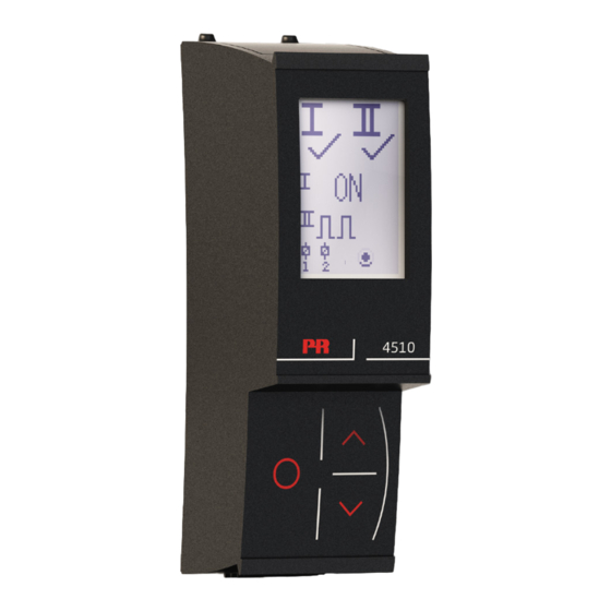
Display layout By default, the PR 4510 enters monitor mode for process surveillance. With the front keys, the 4510 can enter programming or simulation mode. Layout for 3000/4000 and 9000 series products (in monitor mode) PR 3000 / 4000 Line 1 shows the scaled process value. Line 2 shows the selected engineering unit. -
Page 10: Operating The Function Keys / Display
Operating the function keys / display In general When using the PR 4510 for configuration of a PR 4000 or PR 9000 device, you will be guided through all parameters and can choose the settings which fit the application. For each menu there is a scrolling help text which is automatically shown in line 3 on the display. - Page 11 4510 functions The PR 4510 gives access to a number of functions which can be reached by answering “Yes” to the menu point “ADV.SET” (see “4510 settings - routing diagram” on page 10). Display orientation The menu item “ORIEN” allows the user to rotate the display 180 degrees for correct operation with upside down mounting of the device.
-
Page 12: 4510 Settings - Routing Diagram
The gray shaded menus/texts are only shown for guidance, and are not part of the PR 4510 specific submenu. Refer to the individual product manual for each 4000/9000 device to see the product-specific menu structure. PR electronics A/S 4510_Local_Menu.xlsx 4510V101-UK... -
Page 13: Atex/Ukex Installation Drawing
ATEX/UKEX Installation drawing 4500QA01-V2R0 Ex Certificates DEKRA 13ATEX0098 X DEKRA 21UKEX0167X Standards: EN IEC 60079-0 EN 60079-7 Marking: II 3G Ex ec IIC T5 Temperature range -20°C ≤ Ta ≤ +60°C ATEX/UKEX Installation Instructions For safe installation of the 4500 series of products the following must be observed. - Page 14 General installation instructions Year of manufacture can be taken from the first two digits in the serial number. For safe Ex installation the following must be observed: The device must be installed by qualified personnel who are familiar with the national and international laws, directives and standards that apply to this area.
-
Page 15: Iecex Installation Drawing
IECEx Installation drawing 4500QI01-V2R0 Ex Certificates IECEx DEK 13.0026X Standards: IEC 60079-0 IEC 60079-7 Marking: Ex ec IIC T5 Gc Temperature range -20°C ≤ Ta ≤ +60°C IECEx Installation Instructions For safe installation of the 4500 series of products the following must be observed. - Page 16 General installation instructions Year of manufacture can be taken from the first two digits in the serial number. For safe Ex installation the following must be observed: The device must be installed by qualified personnel who are familiar with the national and international laws, directives and standards that apply to this area.
-
Page 17: Fm Installation Drawing
FM Installation drawing 4500QF01-V1R0 FM Certificates FM22US0014X FM22CA0009X Standards: See Certificate Marking: CL I Div 2 GP A,B,C,D T5 CL I Zone 2 AEx/Ex ec IIC T5 Gc Temperature range -20°C ≤ Ta ≤ +60°C AEx/Ex ec Installation Instructions For safe installation of the 4500 series of products the following must be observed. - Page 18 General installation instructions Year of manufacture can be taken from the first two digits in the serial number. For safe Ex installation the following must be observed: The device must be installed by qualified personnel who are familiar with the national and international laws, directives and standards that apply to this area.
-
Page 19: Document History
Document history The following list provides notes concerning revisions of this document. Rev. ID Date Notes 2215 Initial release of the product. 2414 ATEX and IECEx installation drawings updated - reference to PR 4000 devices removed. 4510V101-UK... - Page 20 We are near you, all over the world Our trusted red boxes are supported wherever you are All our devices are backed by expert service and a 5-year with a global reach. This means that we are always nearby warranty. With each product you purchase, you receive and know your local markets well.
- Page 21 Benefit today from PERFORMANCE MADE SMARTER PR electronics is the leading technology company specialized in making industrial process control safer, more reliable and more efficient. Since 1974, we have been dedicated to perfecting our core competence of innovating high precision technology with low power consumption.
Need help?
Do you have a question about the 4510V101- UK and is the answer not in the manual?
Questions and answers