Table of Contents
Advertisement
Quick Links
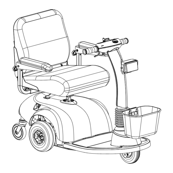
Owner's Operator and Maintenance Manual
HMV
Highly
™
Maneuverable Vehicle
300 and 400
DEALER: This manual MUST be given to
the user of the scooter.
USER: BEFORE using this scooter, read this
manual and save for future reference.
For more information regarding
Invacare products, parts, and services,
please visit www.invacare.com
Download from Www.Somanuals.com. All Manuals Search And Download.
Advertisement
Table of Contents
Troubleshooting

Related Manuals for Invacare HMV 300


Summary of Contents for Invacare HMV 300
- Page 1 DEALER: This manual MUST be given to the user of the scooter. USER: BEFORE using this scooter, read this manual and save for future reference. For more information regarding Invacare products, parts, and services, please visit www.invacare.com Download from Www.Somanuals.com. All Manuals Search And Download.
- Page 2 INVACARE TECHNICAL SUPPORT BEFORE ATTEMPTING TO SERVICE OR OPERATE THIS EQUIPMENT - OTHERWISE, INJURY OR DAMAGE MAY RESULT. NOTE: Updated versions of this manual are available on www.invacare.com. 300 and 400 Part No. 1118395 Download from Www.Somanuals.com. All Manuals Search And Download.
-
Page 3: Table Of Contents
TABLE OF CONTENTS TABLE OF CONTENTS REGISTER YOUR PRODUCT..............6 SPECIAL NOTES ................9 TYPICAL PRODUCT PARAMETERS ..........10 LABEL LOCATIONS ................. 11 On 300 ................................11 On 400 ................................12 SECTION 1—GENERAL GUIDELINES ..........13 Repair or Service Information .......................13 Operation Information ..........................13 Tire Pressure .............................15 Electrical ..............................15 Grounding Instructions........................16... - Page 4 TABLE OF CONTENTS TABLE OF CONTENTS Operating the Scooter ..........................30 Brake Release Lever..........................31 Resetting the Circuit Breaker........................32 Replacing the Fuse............................33 SECTION 7—SEAT ................34 Removing/Installing the Seat........................34 Removing ...............................34 Installing..............................34 Removing/Installing the Seat Post ......................35 Removing ...............................35 Installing..............................35 Adjusting Seat Height..........................36 Adjusting Seat Depth ..........................36 90°...
- Page 5 TABLE OF CONTENTS TABLE OF CONTENTS Removing/Installing the Caster Assemblies ..................48 Removing ...............................48 Installing..............................48 SECTION 12—BATTERIES ..............49 Recommended Battery Type .........................50 Removing/Installing the Batteries on 300....................50 Removing ...............................51 Installing..............................51 Removing/Installing the Batteries on 400....................53 Removing ...............................53 Installing..............................53 Connecting/Disconnecting the Battery Cables on the 400 ............55 Connecting ............................55 Disconnecting ............................56 Charging the Batteries..........................58...
-
Page 6: Register Your Product
3. Receive updates with product information, maintenance tips, and industry news. 4. Invacare can contact you or your provider, if servicing is needed on your product. 5. It will enable Invacare to improve product designs based on your input and needs. - Page 7 11. User's Year of birth: ______________________________________________________ If at any time you wish not to receive future mailings from us, please contact us at Invacare Corporation, CRM Department, 39400 Taylor Parkway, Elyria, OH 44035, or fax to 877-619-7996 and we will remove you from our mailing list.
- Page 8 Fold here Fold here Invacare Product Registration Form Please Seal with Tape Before Mailing Download from Www.Somanuals.com. All Manuals Search And Download.
-
Page 9: Special Notes
It is Invacare’s position that users of powered scooters should be transferred into appropriate seating in vehicles for transportation and use be made of the restraints made available by the auto industry. -
Page 10: Typical Product Parameters
TYPICAL PRODUCT PARAMETERS TYPICAL PRODUCT PARAMETERS OVERALL DIMENSIONS* BASE LENGTH: 44 inches 46 inches BASE WIDTH: 22.5 inches 24 inches STEP HEIGHT (Floor Pan to Ground): 3.5 inches 4.5 inches SEAT HEIGHT (Floor Pan to Seat Cushion): 17-19 inches 17-19 inches SEAT DIMENSIONS WIDTH: 16 inches... -
Page 11: Label Locations
LABEL LOCATIONS LABEL LOCATIONS ON 300 DO NOT operate the scooter unless the tiller is in the locked position. DO NOT lean against or pull forward on the tiller while mounting or dismounting the scooter. Otherwise, injury may occur. -------------------------------------------------------------------------------------------- DO NOT lift scooter up by the front or rear shroud. - Page 12 LABEL LOCATIONS ON 400 DO NOT operate the scooter unless the tiller is in the locked position. DO NOT lean against or pull forward on the tiller while mounting or NOTE: Warning Label 1125362 dismounting the scooter. Otherwise, injury may occur. -------------------------------------------------------------------------------------------- is located under the rear shroud.
-
Page 13: Section 1-General Guidelines
Set-up of the Electronic Control Unit is to be performed ONLY by individuals certified by Invacare. The final tuning adjustments of the controller may affect other activities of the powered scooter. Damage to the equipment could occur under these circumstances. If non-certified individuals perform any work on these units, the warranty is void. - Page 14 SECTION 1—GENERAL GUIDELINES DO NOT climb and/or go UP or DOWN ramps or traverse slopes greater than 8°. When negotiating ramps, if the throttle control lever is released while in the FORWARD motion, the powered scooter will roll back approximately one (1) foot before the brake engages.
-
Page 15: Tire Pressure
SECTION 1—GENERAL GUIDELINES Ensure that the seat is locked in the FORWARD position before and during the operation of the scooter. Otherwise, injury to the user and/or damage to the scooter may result. DO NOT adjust the seat position outside the specifications recommended by the manufacturer. -
Page 16: Grounding Instructions
BATTERIES The warranty and performance specifications contained in this manual are based on the use of deep cycle gel cell batteries. Invacare strongly recommends their use as the power source for this unit. Carefully read battery/battery charger information prior to installing, servicing or operating your powered scooter. -
Page 17: Weight Limitation
SECTION 1—GENERAL GUIDELINES WEIGHT LIMITATION The weight limitation for the 300 is 300 lbs. The weight limitation for the 400 is 400 lbs. If so equipped, the front basket is rated for a maximum loading capacity of 10 lbs. Part No. 1118395 300 and 400 Download from Www.Somanuals.com. -
Page 18: Section 2-Emi Information
SECTION 2—EMI INFORMATION SECTION 2—EMI INFORMATION WARNING CAUTION: IT IS VERY IMPORTANT THAT YOU READ THIS INFORMATION REGARDING THE POSSIBLE EFFECTS OF ELECTROMAGNETIC INTERFERENCE ON YOUR POWERED WHEELCHAIR. Electromagnetic Interference (EMI) From Radio Wave Sources Powered wheelchairs and motorized scooters (in this text, both will be referred to as powered wheelchairs) may be susceptible to electromagnetic interference (EMI), which is interfering electromagnetic energy (EM) emitted from sources such as radio stations, TV stations, amateur radio (HAM) transmitters, two way radios, and... - Page 19 2) This device has been tested to a radiated immunity level of 20 V/m. Modification of any kind to the electronics of this wheelchair as manufactured by Invacare may adversely affect the RFI immunity levels. Part No. 1118395 300 and 400...
-
Page 20: Section 3-Safety/Handling Of Powered Scooters
Individual users often develop skills to deal with daily living activities that may differ from those described in this manual. Invacare recognizes and encourages each individual to try what works best for him/her in overcoming obstacles that they may encounter;... -
Page 21: Stairways
MUST be removed and transported independently of the powered scooter. Extreme caution is advised when it is necessary to move an UNOCCUPIED powered scooter up or down the stairs. Invacare recommends disassembling the scooter and transporting the components (five [5] components on 300 and six [6] components on 400) independently UP or DOWN the stairs. -
Page 22: Section 4-Safety Inspection
SECTION 4—SAFETY INSPECTION SECTION 4—SAFETY INSPECTION NOTE: Every six (6) months take your powered scooter to a qualified technician for a thorough inspection and servicing. Regular cleaning will reveal loose or worn parts and enhance the smooth operation of your powered scooter. To operate properly and safely, your powered scooter must be cared for just like any other vehicle. -
Page 23: Inspect/Adjust Weekly
SECTION 4—SAFETY INSPECTION Tighten locknut if the front wheel wobbles noticeably or loosen locknut if the wheel binds to a stop. Ensure that the fork stem bearing set is tight. Ensure that wheel bearings are clean and free of moisture. Ensure that the bolts and fasteners on the caster assemblies are tight. -
Page 24: Inspect/Adjust Periodically
SECTION 4—SAFETY INSPECTION INSPECT/ADJUST PERIODICALLY Ensure that the powered scooter drives straight (no excessive drag or pull to one side). Check frame for damage and corrosion. Ensure that the brake is easy to engage/disengage. Inspect for no excessive side movement or binding when the drive wheels are raised or turned. -
Page 25: Section 5-Maintenance And Troubleshooting
SECTION 5—MAINTENANCE AND TROUBLESHOOTING SECTION 5—MAINTENANCE AND TROUBLESHOOTING WARNING After ANY adjustments, repair or service and BEFORE use, make sure that all attaching hardware is tightened securely - otherwise, injury or damage may occur. Before performing any maintenance, adjustment or service, turn power OFF and remove key from ignition. -
Page 26: Troubleshooting
SECTION 5—MAINTENANCE AND TROUBLESHOOTING FIGURE 5.1 - LUBRICATION POINTS TROUBLESHOOTING SYMPTOM PROBABLE CAUSE SOLUTION LIMITED DRIVING Battery not charged long enough. Charge batteries overnight or ensure eight DISTANCE. (8) hours of charge between use. Batteries weak, won’t hold Replace batteries. Refer to Removing/ charge. -
Page 27: Section 6-Operation Of The Powered Scooter
SECTION 6—OPERATION OF THE POWERED SCOOTER SECTION 6—OPERATION OF THE POWERED SCOOTER CONTROL PANEL NOTE: For the following information, refer to FIGURE 6.1 and FIGURE 6.2. 1. SPEED CONTROL KNOB - Located on the TOP face of the control panel. The Turtle icon represents the slowest speed and the Rabbit icon represents the fastest speed (FIGURE 6.1). - Page 28 SECTION 6—OPERATION OF THE POWERED SCOOTER DETAIL “A” - 300 DETAIL “B” - 400 Battery Charge Battery Charge Status Indicator LED Indicator LED Indicator LED Status Headlight On/Off Key On/Off Key Indicator LED Switch Switch Switch BATTERY LEVEL STATUS CHARGING Charging Charging Horn...
- Page 29 SECTION 6—OPERATION OF THE POWERED SCOOTER NUMBER FAULT IMPACT ON NOTES OF FLASHES SCOOTER Out of Neutral at Drive Inhibited Throttle is not in neutral position when turn- power up. ing the key switch on. Return the throttle to neutral, turn power off and back on again. Throttle may need to be re-calibrated.
-
Page 30: Operating The Scooter
SECTION 6—OPERATION OF THE POWERED SCOOTER OPERATING THE SCOOTER WARNING After ANY adjustments, repair or service and BEFORE use, make sure that all attaching hardware is tightened securely - otherwise injury or damage may result. DO NOT make sharp turns in the forward or reverse direction at excessive speed. Failure to observe the warning can cause the scooter to tip over and may result in injury to user and/ or damage to the product. -
Page 31: Brake Release Lever
SECTION 6—OPERATION OF THE POWERED SCOOTER NOTE: Throttle control levers operate such that moving one (1) will also move the opposite side throttle control lever. 7. To operate the scooter, depress the throttle control lever in the following manner: A. TO MOVE FORWARD - Push the RIGHT side throttle control lever FORWARD (away from user) or pull the LEFT side throttle control lever REARWARD (towards user). -
Page 32: Resetting The Circuit Breaker
SECTION 6—OPERATION OF THE POWERED SCOOTER Controller Tray Transaxle ENGAGED (PUSH LEVER IN) NOTE: Brake Release Lever on 300 shown. Brake DISENGAGED Release Lever on 400 Brake Release Lever (PULL LEVER operates the same way. OUT) FIGURE 6.3 - BRAKE RELEASE LEVER RESETTING THE CIRCUIT BREAKER WARNING NEVER defeat or bypass the circuit breaker. -
Page 33: Replacing The Fuse
SECTION 6—OPERATION OF THE POWERED SCOOTER REPLACING THE FUSE WARNING NEVER defeat or bypass any fuse. ONLY replace with a fuse of the same rating. NOTE: For this procedure, refer to FIGURE 6.5. 1. Remove seat. Refer to Removing/Installing the Seat on page 34. 2. -
Page 34: Section 7-Seat
SECTION 7—SEAT SECTION 7—SEAT WARNING After ANY adjustments, repair or service and BEFORE use, make sure that all attaching hardware is tightened securely - otherwise injury or damage may result. Before performing any maintenance, adjustment or service, turn power OFF and remove key from ignition. -
Page 35: Removing/Installing The Seat Post
SECTION 7—SEAT REMOVING/INSTALLING THE SEAT POST WARNING Ensure that the seat post mounting screw is properly engaged and locked. Other- wise, injury and/or damage may result. NOTE: Take note of position and orientation of the seat post and seat post mounting screw before removing. -
Page 36: Adjusting Seat Height
SECTION 7—SEAT ADJUSTING SEAT HEIGHT NOTE: For this procedure, refer to FIGURE 7.2. 1. Remove the seat. Refer to Removing/Installing the Seat on page 34. 2. Remove the mounting screw, two (2) washers and locknut securing the seat post to the frame post. -
Page 37: 90° Seat Swivel Adjustment
SECTION 7—SEAT Mounting Screws MOUNTING POSITIONS Seat Base Mounting Screws Back Assembly Seat Base Mounting Screws Back Assembly Seat Base Mounting Screws Mounting Holes Back Assembly Back Assembly Seat Base FIGURE 7.3 - ADJUSTING SEAT DEPTH 4. Adjust back assembly to one (1) of three (3) mounting positions (FIGURE 7.3). 5. -
Page 38: Removing/Installing Seat Positioning Strap
SECTION 7—SEAT NOTE: The seat locks in position at 90° intervals. The seat is locked when an audible “click” is heard. 3. Rotate the seat to the desired position. 4. Release seat lever to lock seat in desired position. NOTE: Ensure that the seat is locked in position before operating the scooter. TOP VIEW VIEW FROM BACK Seat... - Page 39 SECTION 7—SEAT Arm Frame Seat Positioning Strap Seat Positioning Strap Washer Mounting Screw Mounting Screw Washer FIGURE 7.5 - REMOVING/INSTALLING SEAT POSITIONING STRAP Part No. 1118395 300 and 400 Download from Www.Somanuals.com. All Manuals Search And Download.
-
Page 40: Section 8-Arms
SECTION 8—ARMS SECTION 8—ARMS WARNING After ANY adjustments, repair or service and BEFORE use, make sure all attaching hardware is tightened securely - otherwise injury or damage may result. Before performing any maintenance, adjustment or service, turn power OFF and remove key from ignition. -
Page 41: Adjusting Arm Angle
SECTION 8—ARMS CAUTION The arm can be adjusted to a maximum distance of 4½ inches from the inside of the arm to the top of the mounting shaft. If the arm is adjusted beyond the maximum 4½ inches, the arm will fall out. 2. -
Page 42: Replacing Armrest Pads
SECTION 8—ARMS 3. Reinstall the lock knob that secures the arm to the arm mounting tube and tighten securely. 4. Repeat STEPS 1-3 for opposite arm, if necessary. Lock Knob Arm Mounting Tube FIGURE 8.3 - ADJUSTING ARM HEIGHT REPLACING ARMREST PADS NOTE: For this procedure, refer to FIGURE 8.4. -
Page 43: Section 9-Tiller Adjustment
SECTION 9—TILLER ADJUSTMENT SECTION 9—TILLER ADJUSTMENT ADJUSTING THE TILLER ANGLE WARNING Before performing any maintenance, adjustment or service, turn power OFF and remove key from ignition. Ensure that tiller is properly adjusted before driving the scooter. After making ANY tiller angle adjustments and BEFORE use, the tiller MUST be securely locked into position. -
Page 44: Section 10-Rear Shroud
SECTION 10—REAR SHROUD SECTION 10—REAR SHROUD WARNING After ANY adjustments, repair or service and BEFORE use, make sure that all attaching hardware is tightened securely - otherwise injury or damage may result. Before performing any maintenance, adjustment or service, turn power OFF and remove key from ignition. -
Page 45: Section 11-Wheels And Casters
SECTION 11—WHEELS AND CASTERS SECTION 11—WHEELS AND CASTERS WARNING After ANY adjustments, repair or service and BEFORE use, make sure that all attaching hardware is tightened securely - otherwise injury or damage may result. Before performing any maintenance, adjustment or service, turn power OFF and remove key from ignition. - Page 46 SECTION 11—WHEELS AND CASTERS DETAIL “A” - 300 Keystock WARNING: PINCH POINT Cutout Washer Scooter Frame Drive Shaft Hex Nut Drive Wheel DETAIL “B” - 400 Swingarm Scooter Frame Keystock Washer Hex Nut Drive Shaft Drive Wheel FIGURE 11.1 - REMOVING/INSTALLING THE DRIVE WHEELS 300 and 400 Part No.
-
Page 47: Removing/Installing The Front Wheel
SECTION 11—WHEELS AND CASTERS REMOVING/INSTALLING THE FRONT WHEEL NOTE: Take note of position and orientation of wheel and mounting hardware before removing. NOTE: For this procedure, refer to FIGURE 11.2. REMOVING 1. Turn power OFF and remove the key from the ignition. 2. -
Page 48: Removing/Installing The Caster Assemblies
SECTION 11—WHEELS AND CASTERS REMOVING/INSTALLING THE CASTER ASSEMBLIES NOTE: For this procedure, refer to FIGURE 11.3. REMOVING 1. Apply a wrench to the hex nut on the caster assembly. 2. Turn the hex nut COUNTER-CLOCKWISE to loosen and remove the caster wheel. 3. -
Page 49: Section 12-Batteries
DO NOT tip the batteries. Keep the batteries in an upright position. Invacare strongly recommends that battery installation and battery replacement always be done by a qualified technician. All battery terminals caps (two [2] on the LEFT battery and two [2] on the RIGHT battery) MUST be installed prior to use. -
Page 50: Recommended Battery Type
RECOMMENDED BATTERY TYPE WARNING The warranty and performance specifications contained in this manual are based on the use of deep cycle gel cell batteries. Invacare strongly recommends their use as the power source for this unit. CAUTION Failure to use the correct battery size and/or voltage may cause damage to the powered scooter and give unsatisfactory performance. -
Page 51: Removing
SECTION 12—BATTERIES REMOVING NOTE: For this procedure, refer to FIGURE 12.2. 1. Place the powered scooter in a well ventilated area where work can be performed without risking damage to carpeting or floor covering. 2. Turn power OFF and remove the key from the ignition. 3. - Page 52 SECTION 12—BATTERIES 7. Connect the RED and BLACK battery connector to the wiring harness assembly. Tighten securely. 8. Secure batteries in the battery tray using the battery strap (Detail “A” of FIGURE 12.2). 9. Reinstall the rear shroud. Refer to Removing/Installing the Rear Shroud on page 44. 10.
-
Page 53: Removing/Installing The Batteries On 400
SECTION 12—BATTERIES REMOVING/INSTALLING THE BATTERIES ON NOTE: For this procedure, refer to FIGURE 12.2. REMOVING 1. Place the powered scooter in a well ventilated area where work can be performed without risking damage to carpeting or floor covering. 2. Turn power OFF and remove the key from the ignition. 3. - Page 54 SECTION 12—BATTERIES DETAIL “A” - BATTERY LIFTING STRAPS DETAIL “B” - BUILT-IN LIFTING STRAPS Built-in Lifting Battery Lifting Straps Straps DETAIL “C” - BATTERY WIRING HARNESS Wiring Harness Connectors BLACK Battery BLACK Battery Connector Connector LEFT Battery RIGHT Battery POSITIVE (+) RED NEGATIVE (-) BLACK NEGATIVE (-) BLACK POSITIVE (+) RED...
-
Page 55: Connecting/Disconnecting The Battery Cables On The 400
SECTION 12—BATTERIES CONNECTING/DISCONNECTING THE BATTERY CABLES ON THE 400 WARNING On 400 only - Battery terminal configuration shown below MUST be used. Batteries that have the reversed terminal configuration MUST NOT be used - otherwise serious injury or damage may occur. DO NOT USE POSITIVE (+) Battery... -
Page 56: Disconnecting
SECTION 12—BATTERIES WARNING When connecting the battery cables to the batteries, the battery cables MUST be connected to the battery terminals/posts as shown in FIGURE 12.5, otherwise dam- age to the battery cable may result when installing battery terminal caps. 2. - Page 57 SECTION 12—BATTERIES 5. Slide terminal cap(s) UP on the battery cable(s). 6. Disconnect battery cable(s) from battery(ies) terminal(s)/post(s): A. POSITIVE (+) RED battery cable from the POSITIVE (+) battery terminal/post. B. NEGATIVE (-) BLACK battery cable from NEGATIVE (-) battery terminal/post. TO BLACK BATTERY CONNECTOR DETAIL “A”...
-
Page 58: Charging The Batteries
SECTION 12—BATTERIES CHARGING THE BATTERIES WARNING NEVER attempt to recharge the batteries by attaching cables directly to the battery terminals or clamps. DO NOT attempt to recharge the batteries and operate the powered scooter at the same time. CAUTION New batteries MUST be fully charged prior to initial use of the powered scooter. Always charge new batteries before initial use or battery life will be reduced. -
Page 59: Battery Charger Operation - Charger Indicator Light On Tiller
SECTION 12—BATTERIES AC Power Cord Rear Shroud Rear Shroud Charger Port NOTE: Charger port on 300 shown. Charger port on 400 is similar. FIGURE 12.6 - CHARGING THE BATTERIES BATTERY CHARGER OPERATION - CHARGER INDICATOR LIGHT ON TILLER NOTE: If the scooter is turned on while charging, the battery charge indicator will show the batteries at FULL charge. -
Page 60: Section 13-Transporting
SECTION 13—TRANSPORTING SECTION 13—TRANSPORTING WARNING After ANY adjustments, repair or service and BEFORE use, make sure that all attaching hardware is tightened securely - otherwise injury or damage may result. Before performing any maintenance, adjustment or service, turn power OFF and remove key from ignition. -
Page 61: Disassembling
SECTION 13—TRANSPORTING Refer to Removing/Installing the Seat on page 34 Refer to Removing/Installing the Rear Shroud on page 44 Refer to Removing/Installing the Front Basket on page 64 Refer to Removing/Installing the Batteries on 300 on page 50 Refer to Adjusting the Tiller Angle on page 43 FIGURE 13.1 - TRANSPORTING THE SCOOTER - 300 NOTE: For this procedure, refer to FIGURE 13.2. -
Page 62: Assembling
SECTION 13—TRANSPORTING A. Use the one hand to firmly hold the tiller handle. B. Using the other hand, firmly hold the YELLOW frame lock lever [located under marker label # 2]and pull UP to the Unlocked position as shown in Detail “C” of FIGURE 13.2. - Page 63 SECTION 13—TRANSPORTING DETAIL “A” - ASSEMBLE/DISASSEMBLE 400 DETAIL “B” - DISCONNECT MOTOR AND BATTERY CONNECTORS Motor Connector Motor Connector Refer to Removing/Installing the Seat on page 34 Controller Refer to Removing/Installing the Rear Shroud on page 44 Refer to Removing/ Installing the Batteries on 400 on page 53 Refer to Removing/...
-
Page 64: Section 14-Scooter Accessories
SECTION 14—SCOOTER ACCESSORIES SECTION 14—SCOOTER ACCESSORIES WARNING After ANY adjustments, repair or service and BEFORE use, make sure that all attaching hardware is tightened securely - otherwise injury or damage may result. Before performing any maintenance, adjustment or service, turn power OFF and remove key from ignition. -
Page 65: Installing/Removing The Crutch/Cane Holder
SECTION 14—SCOOTER ACCESSORIES INSTALLING/REMOVING THE CRUTCH/CANE HOLDER NOTE: The Crutch/Cane Holder, Safety Flag and Oxygen Holder all install into the accessory tube; ONLY one (1) of these may be installed at a time. WARNING The installation of the crutch/cane holder onto the back of the scooter seat signifi- cantly increases the length of the scooter. -
Page 66: Installing/Removing The Safety Flag
SECTION 14—SCOOTER ACCESSORIES INSTALLING/REMOVING THE SAFETY FLAG NOTE: For this procedure, refer to FIGURE 14.3. WARNING The installation of the safety flag onto the back of the scooter seat significantly increases the length of the scooter. When turning the scooter or swiveling the scooter seat, it is important to take note of this increased length - otherwise, injury and/or damage to the surrounding property may result. -
Page 67: Installing/Removing The Walker Holder
SECTION 14—SCOOTER ACCESSORIES INSTALLING/REMOVING THE WALKER HOLDER NOTE: Reverse this procedure to remove the walker holder. NOTE: For this procedure, refer to FIGURE 14.4. 1. If necessary, loosen but do not remove Mounting the mounting knob. Knob Seat 2. Install the walker holder into the accessory tube. - Page 68 SECTION 14—SCOOTER ACCESSORIES INSTALLING/REMOVING THE REAR MOUNTED BASKET NOTE: For this procedure, refer to FIGURE 14.6. WARNING The rear mounted basket is rated for a maximum capacity of ten (10) lbs. After ANY adjustments, repair or service and BEFORE use, make sure that all attaching hardware is tightened securely.
- Page 69 NOTES Part No. 1118395 300 and 400 Download from Www.Somanuals.com. All Manuals Search And Download.
- Page 70 NOTES 300 and 400 Part No. 1118395 Download from Www.Somanuals.com. All Manuals Search And Download.
- Page 71 In the event you do not receive satisfactory warranty service, please write directly to Invacare at the address on the bottom of the back cover. Provide dealer's name address, date of purchase, indicate nature of the defect and, if the product is serialized, indicate the serial number.
- Page 72 Invacare Corporation Canada One Invacare Way 570 Matheson Blvd E Unit 8 Invacare is a registered trademark of Elyria, Ohio USA Mississaugua Ontario Invacare Corporation. 44036-2125 L4Z 4G4 Canada Teflon is a registered trademark of E.I. 800-333-6900 800-668-5324 DuPont Nemours and Company.
- Page 73 Free Manuals Download Website h p://myh66.com h p://usermanuals.us h p://www.somanuals.com h p://www.4manuals.cc h p://www.manual-lib.com h p://www.404manual.com h p://www.luxmanual.com h p://aubethermostatmanual.com Golf course search by state h p://golfingnear.com Email search by domain h p://emailbydomain.com Auto manuals search h p://auto.somanuals.com TV manuals search h p://tv.somanuals.com...
Need help?
Do you have a question about the HMV 300 and is the answer not in the manual?
Questions and answers