Table of Contents
Advertisement
Installation, operation
and maintenance manual
Magforce
STD/STG/STW/SKD/SKS/STN
Linear Actuators
Read this manual before installing, operating
or maintaining this actuator. Failure to follow
safety precautions and instructions could
cause actuator failure and result in serious
injury, death or property damage.
Advertisement
Table of Contents

Related Manuals for SKF Magforce STD 10007 series


Summary of Contents for SKF Magforce STD 10007 series
- Page 1 Installation, operation and maintenance manual Magforce STD/STG/STW/SKD/SKS/STN Linear Actuators Read this manual before installing, operating or maintaining this actuator. Failure to follow safety precautions and instructions could cause actuator failure and result in serious injury, death or property damage.
- Page 2 Operating instructions Linear drives MAGFORCE - STD - STG - STW - - SKD - SKG - SKW - - STN - ©1996 by Magnetic GmbH, Copying and passing on to third parties is only permitted with Magnetic’s approval. 531E,0001/2.99...
-
Page 3: Table Of Contents
Operating instructions Table of Contents Page Table of Contents 1. Overview of linear drives STD...(three phase current),STG... (direct current), STW...(alternating current), SKD... (three phase current), SKG...(direct current), SKW...(alternating current), STN...(three phase current) 2. Safety 2.1 General safety instructions 2.2 Use in accordance with the regulations 2.3 Identification of dangers 2.4 Safety at work 2.5 Technical progress... -
Page 4: Overview Of Linear Drives
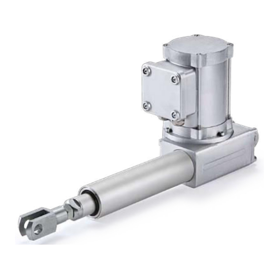
Operating instructions Overview linear drives STD... (three phase current), STG... (direct current), STW... (alternating current), SKD... (three phase current), SKG... (direct current), SKW... (alternating current), STN... (three phase current) 549x000120 Fig. 1 Overview linear drive MAGFORCE 1. Motor unit MAGFORCE STW/STD/SKD (alternating current / three phase current) 2. -
Page 5: Safety
Operating instructions Safety General safety instructions MAGFORCE linear drives have been designed, built and inspected for safe operation in accordance with state-of-the-art technology the standards (Machine Directive 89/392 EWG, Low Voltage Directive 73/23 EWG and EMV Directive 897 336 EWG) and have left the factory in a perfect and safe state. -
Page 6: Safety At Work
Operating instructions Safety at work • Depending on the location of where the linear drive will be used, pro tective devices must be installed which protect persons from crush injuries. Please read the relevant insurance liability and product specific regulations. The instructions regarding safety at work •... -
Page 7: Assembly And Installation
Operating instructions Assembly and installation Assembling the linear drive The linear drive is fitted to the rear trunion and the fork head (see Fig. 2). We recom- WARNING! mend that an adapter piece and fork head are used to fix to the push tube. Rotation of The load to be moved must always act the push tube during operation is not permitted. -
Page 8: Electrical Connections
Operating instructions Electrical connection Electrical connections for linear drives The motors must be connected in accordance with Fig. 4. The direction of rotation is WARNING! reversed by polarity reversal via relays or push buttons. The installation must be performed by Direct polarity reversal must be avoided due to the inertia force and to protect the swit- trained electricians. -
Page 9: Electrical Connection Of Linear Drives With Stroke Limit Switching
Operating instructions 4.2 Electrical connection of linear drives with stroke limit switching If the linear drive is equipped with end stroke limit switches, the drive must be connected in accordance with Fig. 5. WARNING After the electrical connections have been made, it is necessary to see whether the The installation must be performed by direction of rotation (polarity, phase) of the motor is correct by briefly switching the trained electricians. -
Page 10: Electrical Connection Of Potentiometer
Operating instructions Electrical connection of potentiometer If the linear drive is equipped with a potentiometer, the potentiometer must be connected in accordance with Fig. 6. The motor is connected according to voltage rating as described in Chapter 4.1. customer evaluate Fig. -
Page 11: Setting The Potentiometer (Optional)
Operating instructions Setting the potentiometer (optional) The optional potentiometer is fitted to the drive casing (see Fig. 2). The electrical connections are described in Chapter 4.3. The data for the potentiometer are as follows: Resistance: max. 1 kOhm ± 5%, linear characteristic curve ATTENTION! nominal load capacity 3 W at 40°C, 2 W at 70°C If the potentiometer was installed at the... -
Page 12: Technical Data
Operating instructions Technical data Mechanical and electrical data Type STD (Three-phase current) STD 10007-... STD 12010-... STD 15020-... STD 15040-... Pressure / tensile strength [kN] Automatic locking device Static load [kN] Thrust speed [mm/sec] Stroke length [mm] max. 700 mm Mains supply [V/50 Hz] 3 x 400... - Page 13 Operating instructions Typ STG (Direct current) STG10007-... STG 12010-... STG 15020-... STG 15040-... Pressure / tensile strength [kN] Automatic locking device Static load [kN] Thrust speed [mm/sec] Stroke length [mm] max. 700 mm Mains supply [V DC] Power consumption Current consumption Operating time (S3 10 min.) Ambient temperature [°C]...
- Page 14 Operating instructions Type STW (Alternating current) STW 5007-... STW7010-... STW 10020-... STW 15040-... Pressure / tensile strength [kN] Automatic locking device Static load [kN] Thrust speed [mm/sec] Stroke length [mm] max. 700 mm Mains supply [V/50 Hz] 1 x 230 1 x 230 1 x 230 1 x 230...
- Page 15 Operating instructions Type SKD (Three-phase current) SKD 10007-... SKD 12010-... SKD 15020-... SKD 15040-... Pressure / tensile strength [kN] Automatic locking device Static load [kN] Thrust speed [mm/sec] 24,5 20,6 10,6 Stroke length [mm] max. 700 mm Mains supply [V/50 Hz] 3 x 400 3 x 400 3 x 400...
- Page 16 Operating instructions Type SKG (Direct current) SKG 6005-... SKG 10010-... SKG 13020-... SKG 15040-... Pressure / tensile strength [kN] Automatic locking device Static load [kN] Thrust speed [mm/sec] Stroke length [mm] max. 700 mm Mains supply Power consumption Current consumption Operating time (S3 10 min.) Ambient temperature [°C]...
- Page 17 Operating instructions Type SKW (Alternating current) SKW 4005-... SKW 7010-... SKW 10020-... SKW 13040-... Pressure / tensile strength [kN] Automatic locking device Static load [kN] Thrust speed [mm/sec] Stroke length [mm] max. 700 mm Mains supply [V/50 Hz] 1 x 230 1 x 230 1 x 230 1 x 230...
- Page 18 Operating instructions Type STN (Three-phase current) STN 5007-... STN 10007-... STN 10010-... Pressure / tensile strength [kN] Automatic locking device Static load [kN] Thrust speed [mm/sec] 26,5 Stroke length [mm] max. 700 mm Mains supply [V/50 Hz] 3 x 400 3 x 400 1 x 230 Power consumption...
-
Page 19: Care And Maintenance
Operating instructions stroke stroke + 290 SW 30 Fig.9 549e000114 To scale drawing of adapter SW 27 SW 30 stroke stroke + 377 Fig.10 stroke + 419 549e000113 To scale drawing of fork head Maintenance and care The linear drive is equipped with a special nut and sufficient lubrication reserve and therefore requires no maintenance. -
Page 20: Technical Support
Operating instructions Technical support If faults occur during the operation or guarantee period which cannot be rectified by trained electricians, please contact our internal experts. 10. Replacement parts and accessories Accessory Article number Stroke limit switch-end device 0 ...300 mm stroke 1043,0268 Stroke limit switch-end device 100 ...
Need help?
Do you have a question about the Magforce STD 10007 series and is the answer not in the manual?
Questions and answers