Table of Contents
Advertisement
Quick Links
Advertisement
Table of Contents

Subscribe to Our Youtube Channel
Related Manuals for SKF ST-102P Series


Summary of Contents for SKF ST-102P Series
- Page 1 SKF ST-102P-XX-XX CONTROLLER (Original Operating and Service Manual according to EU Directive 2014/30) Date: 23.8.2022 Document no: ST-102P-xx-xx Version: 1G Read this manual before installing or commissioning the product and keep it at hand for later reference.
- Page 2 Technical documentation has been drawn up in accordance with Part B of Annex VII. The manufacturer undertakes to deliver the technical documentation to national authorities in electronic format when so requested. The company authorised to compile the technical documents is SKF (U.K.) Limited, 2 Canada Close, Banbury, Oxfordshire, OX16 2RT, GBR. Description:...
-
Page 3: Masthead
The instructions contain no statements regarding the warranty or liability for defects. That information can be found in our General Terms of Payment and Delivery. Training We conduct detailed training in order to enable maximum safety and efficiency. We recommend taking advantage of this training. For further information, contact your authorised SKF dealer or the manufacturer. -
Page 4: Table Of Contents
Table of contents Masthead ......................................3 Table of contents..................................... 4 Safety alerts, visual presentation, and layout ..........................5 1. Safety instructions ..................................6 General safety instructions..............................6 General electrical safety instructions .............................6 General behaviour when handling the product........................6 Intended use ..................................6 Persons authorised to use the product ..........................7 Foreseeable misuse ................................7 Referenced documents ................................7... -
Page 5: Safety Alerts, Visual Presentation, And Layout
Safety alerts, visual presentation, and layout While reading these instructions, you will encounter various symbols, illustrations, and text layouts intended to help you navigate and understand the instructions. Their meaning is explained below. Safety alerts: Activities that present specific hazards (to life and limb or possible damage to property) are indicated with safety alerts. Always be sure to follow the instructions given in the safety alerts. -
Page 6: Safety Instructions
" Unauthorised changes may have unexpected effects on the safety and performance of the product, which is why making such changes is prohibited. Only original SKF spare parts and SKF accessories may be used. " Any unclear points regarding proper condition or correct assembly/operation must be clarified. Operation is prohibited until issues have been clarified. -
Page 7: Persons Authorised To Use The Product
Persons authorised to use the product Operator A person who is qualified by training, knowledge, and experience to carry out the functions and activities related to normal operation. This includes avoiding possible hazards that may arise during operation. Mechanical specialist Person with appropriate professional education, knowledge, and experience to detect and avoid the hazards that may arise during transport, installation, start-up, operation, maintenance, repair and disassembly. -
Page 8: Notes On The Type Plate
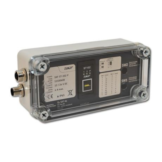
Notes on the type plate The type plate provides important data such as the type designation, order number, and sometimes regulatory characteristics. To avoid loss of this data in case the type plate becomes illegible, it should be entered in the manual. Figure 1. -
Page 9: Assembly, Maintenance, Fault, Repair
Assembly, maintenance, fault, repair Prior to the start of this work, all relevant persons must be notified of it. At a minimum, the following safety measures must be taken before any work is done: " Unauthorised persons must be kept away "... -
Page 10: Return Consignments
Order no. XXX Marking of return consignments Storage SKF products are subject to the following storage conditions: " Storage indoors in a dry, vibration-free environment with a low level of dust and ambient temperate of a room temperature. " No corrosive, aggressive substances or factors permitted in the storage space (e.g., UV radiation, ozone) "... -
Page 11: Controller St-102P-Ps / St-102P-Ps-Mm
Read and follow the safety precautions and general instructions in this manual and in the SKF manual "Safety and general instructions for lubrication systems." Failure to follow these instructions may result in a serious injury or damage to the lubrication system or the lubricated equipment. -
Page 12: Indicators Above The Function Button
4.1.1 Indicators above the function button Status Meaning Lubrication interval 3 line 1 was pressurised last Indicator 1 is lit Lubrication interval 3 line 2 was pressurised last Indicator 2 is lit Indicators 1 and P are lit Line 1 is being pressurised Indicators 2 and P are lit Line 2 is being pressurised Indicators 1 and 2 are lit... -
Page 13: Function Button Functions
4.1.2 Function button functions Pressing the function button when the lubrication program is calculating the lubrication interval will immediately initiate an extra lubrication cycle, bypassing the pre-set lubrication interval value. In DuoFlex systems, the two lines will be lubricated successively. The lubrication cycle following the extra lubrication will be initiated after the pre-set lubrication interval is complete. -
Page 14: St-102P-Ps / St-102P-Ps-Mm Controller Components
ST-102P-PS / ST-102P-PS-MM controller components ST-102P-PS / ST-102P-PS-MM controller components Symbol Component Function Connector Function button connector Selector switch Program selector switch Selector switch Program selector switch Selector switch Program selector switch Selector switch Programme selector switch Rotary switch Lubrication interval setting Rotary switch Pressurisation time setting LED indicator... -
Page 15: Changing Lubrication System Settings From The Circuit Board
It is recommended to change the settings when the controller is unplugged, which means that the changes will take effect when the controller is plugged back in. Selector switch J4A, lubrication system selection 4.3.1 11500608 ST-102P-PS Selector switch J4A Meaning Closed SKF MonoFlex, single-line operation Selector switches J4B, J4C and J4D: Meaning Closed Open Open Electric pump. -
Page 16: 11500600 St-102P-Ps-Mm
4.3.2 11500600 ST-102P-PS-MM Selector switch J4A Meaning Closed SKF MonoFlex, single-line operation Open SKF DuoFlex, a dual-line system Selector switches J4B, J4C and J4D: Meaning Closed Open Open Multilube/Minilube pump control. The main line is maintained pressurised throughout the entire pressurisation time. The pump will stop when the pressure switch acknowledges. -
Page 17: Changing Lubrication Parameter Settings Using Rotary Switches 3 1150608 St-102P-Ps
Factory settings: J4:A (Single-line Closed operation) J4:B (Pressure Closed maintenance Multilube / Minilube) J4:C (Pressure Open maintenance Multilube / Minilube) J4:D (Pressure Open maintenance Multilube / Minilube) J4:E (Multilube / Closed Minilube operation) J9 (Settings with the Closed function button) SW1 (Not in use) Position 0 SW2 (Not in use) -
Page 18: Maximum Pressurization Time (Sw 2)
(min) 4.4.3 Controller setting example SKF MonoFlex, single-line system with pneumatic pump: " J4A and J4C on, other selection switches off " Lubrication interval 15 min = SW 1 position 2 " Maximum pressurization time 4 min = SW 2 position 3 In the example, lubrication time max. -
Page 19: Changing Lubrication Parameter Settings Using The Function Button 3 1150600 St-102P-Ps-Mm
Changing lubrication parameter settings using the function button 3 1150600 ST- 102P-PS-MM The function button allows users to set the lubrication interval, maximum pressurisation time and, in progressive systems, the required number of lubrication pulses. 4.5.1 Lubrication cycle setting Lubrication cycle refers to the time in which all lubrication points get lubricated. Press the function button for approximately 5 seconds. -
Page 20: Setting The Maximum Pressurisation Time
4.5.2 Setting the maximum pressurisation time Set the system's maximum pressurisation time to match the minimum time required for increasing the entire system's pressure to the pressure switch acknowledgment level. Press the function button until indicator 2 starts flashing rapidly (approximately 10 seconds). Now the maximum pressurisation time can be set. -
Page 21: Electrical Connections
Electrical connections 4.6.1 11500608 ST-102P-PS operating voltage connection and 40PGxx lubrication pump connection Connection M12 F (female) - Lubrication pump unit connection. Cable M12 connector 4x0.34 10m Connection M12 M (male) 3 ST-102P-PS operating voltage connection. 2 x 0.75 cable. The wire colours and the operating voltage polarity can be checked from the table below in line with the cable delivered with the controller. -
Page 22: 11500600 St-102P-Ps-Mm Operating Voltage Connection And Minilube Lubrication Pump Connection
4.6.2 11500600 ST-102P-PS-MM operating voltage connection and Minilube lubrication pump connection The 11500002 CABLE SET MINI ST102PMM L=10m cable is used for the connection. On the side of the pump, the cable has open wires for connection to the pump9s terminal block. The controller side is equipped with a Bulgin male connector. -
Page 23: 11500600 St-102P-Ps-Mm Operating Voltage Connection And Multilube Lubrication Pump Connection
4.6.3 11500600 ST-102P-PS-MM operating voltage connection and Multilube lubrication pump connection The 11500001 CABLE SET MLP-ST102PMM L=10m cable is used for the connection. On the side of the pump, the cable is equipped with a Bulgin female connector for connection to the pump9s Bulgin male connector. -
Page 24: Technical Specifications
Technical specifications Value Operating temperature -30&+80°C range Protection class IP66 Dimensions (W x H x D) 67 x 80 x 170 mm (W x H x D) Weight 350 g Operating voltage 12 or 24 VDC (10.5V & 32VDC) Power consumption Depends on the lubrication system being controlled, 0...4 A Fuse Self-resetting fuse, 4 A, on the circuit board... -
Page 25: Troubleshooting Table
Troubleshooting table Description of malfunction Cause of malfunction Solution User interface indicators do not The controller does not receive Check the operating voltage. light up. operating voltage. Replace the function button. Keyboard LED indicators have Turn off the power for a while and gone. -
Page 26: Appendices
5. Appendices China RoHS Table...
Need help?
Do you have a question about the ST-102P Series and is the answer not in the manual?
Questions and answers