Table of Contents
Advertisement
Available languages
Available languages
Quick Links
Advertisement
Chapters
Table of Contents

Related Manuals for Fronius ROB I/O


Summary of Contents for Fronius ROB I/O
- Page 1 / Battery Charging Systems / Welding Technology / Solar Electronics Bedienungsanleitung ROB I/O MIG/MAG-Systemerweiterung Operating Instructions MIG/MAG system extension Mode d’emploi Extension système MIG/MAG 42,0410,1048 002-11042012...
-
Page 3: Table Of Contents
Allgemeine Grundlagen ..........................8 Gerätekonzept ............................8 Montage ROB I/O ............................9 Sicherheit ..............................9 ROB I/O durch Montage-Bohrungen befestigen ..................9 ROB I/O an Hutschiene befestigen ......................9 Technische Daten ............................11 Versorgung (über das Local-Net) ......................11 Digitale Eingänge ............................ 11 Digitale Ausgänge ........................... -
Page 4: Kurzbeschreibung
Gegenüber dem LocalNet und dem Schweißpotential Für einen maximalen Spannungsunterschied von 100 V Prozeßdatenbrei- ROB I/O erhöht die Prozeßdaten-Breite des Interbus 2 MB von 96 Bit auf 112 Bit. Auf- grund der erweiterten Prozeßdatenbreite, sind am Interbus 2 MB zusätzliche Eingangs- und Ausgangssignale verfügbar. - Page 5 Eingangssignale Eingang Stromquelle Kommentar Bereich Aktivität vom Roboter zur Schweißen ein High Stromquelle Roboter bereit High Betriebsarten Bit 0 High Betriebsarten Bit 1 High Betriebsarten Bit 2 High Unused Unused Unused Gas Test High Drahtvorlauf High Drahtrücklauf High Quellenstörung quittieren High Positionssuchen High...
- Page 6 Ausgangssignale Eingang Stromquelle Kommentar Bereich Aktivität vom Roboter zur Stromflußsignal High Stromquelle (Lichtbogen aktiv) Limitsignal (nur RCU 5000i) Prozeß aktiv High Hauptstromsignal High Kollisionsschutz High Schweißbrenner Stromquelle bereit High Kommunikation bereit High Reserve Error-Nummer Bit 0 (Wert 1) High Error-Nummer Bit 1 (Wert 2) High Error-Nummer Bit 2 (Wert 4) High...
-
Page 7: Rob I/O Konfigurieren
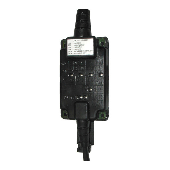
Es erscheint das Dialogfenster „Configuration Fieldbus“ Auf den Ordner „System Settings“ klicken Im rechten Anzeigefenster „Configura- tion Fieldbus“ den Eintrag ROB I/O = „NOT CONNECT“ öffnen Es erscheint „Connect“ Das Kontrollfeld neben „Connect“ ankreu- Der Eintrag ROB I/O = „NOT CON- NECT“... - Page 8 (1) (9) (10) (12) (11) Abb.1 Anzeigen und Anschlüsse an der Feldbus-Systemerweiterung ROB I/O (1) Anzeige DATA OK ... leuchtet, wenn ROB I/O am LocalNet angeschlossen und die Feldbus-Steuerung versorgt ist (6) Digitale Eingänge (HI), an Klemme 1, mit externer 24 V - Ansteuerung Wichtig! Anstelle der Eingänge (6) können auch die potentialfreien Eingänge (7) ver-...
-
Page 9: Gerätespezifische Merkmale
(Klemme 1/10) GND uP (Klemme 1/11) GND input GND input Klemme 1/10 ..LO Input 2 Klemme 1/11 ..GND Input 2 Abb.2 Eingangssignale Feldbus-Erweiterung ROB I/O Stromquelle Automat + 24 V von der Automatensteuerung + 24 V von der Automatensteuerung max. -
Page 10: Allgemeines
Grundlagen 1.00.16 (Bussteuerung) unterstützt. Bei älteren Software-Versionen ist ein Update erforderlich. Gerätekonzept ROB I/O ist für den Einbau in einen Schaltschrank geeignet, kann aber praktisch an beliebiger Position montiert werden. Vorteile: Verbindung zur Feldbus-Steuerung über standardisierte LocalNet-Schnittstelle Kein Umbau der Feldbus-Steuerung notwendig... -
Page 11: Montage Rob I/O
Warnung! Fehlerhaft durchgeführte Arbeiten können schwerwiegende Personen- und Sachschäden verursachen. Nachfolgend beschriebene Tätigkeiten dürfen nur von geschultem Fachpersonal durchgeführt werden! Beachten Sie die Sicher- heitsvorschriften. ROB I/O durch Wichtig! Bei Montage des ROB I/O durch Montage-Bohrun- die Montage-Bohrungen (1) Folgendes gen befestigen beachten: Nur geeignete Schrauben verwenden (Bohrungsdurchmesser Ø... -
Page 12: Rob I/O An Hutschiene Befestigen
ROB I/O an Fixiernasen (4) der Hutschienenauf- Hutschiene nahme an der Hutschiene (5) einha- befestigen (Fortsetzung) Abb.6 ROB I/O an Hutschiene befestigen ROB I/O an der Unterseite gegen die Hutschiene (5) drücken Arretierung rastet ein andrücken Abb.7 Vorderansicht ROB I/O an Hutschiene... -
Page 13: Technische Daten
Technische Daten Versorgung (über Bedingung minimal typisch maximal das Local-Net) Versorgungsspannung Dauerbetrieb 15 V 24 V 30 V Stromaufnahme Versorgungsspannung = 24 V 50 mA 100 mA 300 mA Stromaufnahme Standby Versorgungsspannung = 24 V 50 mA 60 mA 80 mA Digitale Eingänge Bedingung Potentialfrei (LO) - Page 15 Mounting ROB I/O ............................9 Safety ............................... 9 Fasten ROB I/O via mounting bores ......................9 Fastening the ROB I/O to the top-hat rail ....................9 Technical data .............................. 11 Power supply (via the Local-Net) ......................11 Digital inputs ............................11 Digital outputs ............................
-
Page 16: Brief Description
100 V Process data The ROB I/O module enables the 2 MB Interbus to transfer 112 bit wide instead of 96 bit width wide process data. As a result, additional input and output signals are available on the 2 MB Interbus. - Page 17 Input signals Power source input Commentary Range Activity from the robot to Welding on High the power source Robot ready High Operating modes Bit 0 High Operating modes Bit 1 High Operating modes Bit 2 High Unused Unused Unused Gaz test High Wire feeding High...
- Page 18 Output signals Power source input Commentary Range Activity from the robot to Current-flow signal High the power source (with active welding arc) Limit signal (nur RCU 5000i) Process active High Main current signal High Welding torch anti-collision High sensing Power source ready High Communication ready High...
-
Page 19: How To Configure Rob I/O
In the right-hand Configuration Field- bus display window, open entry ROB I/O = „NOT CONNECT“ “Connect“ appears. Check the checkbox beside „Connect“ The entry ROB I/O = „NOT CON- NECT“ changes to ROB I/O = „CON- NECT“ Double-click the entry ROB I/O = „CONNECT“... -
Page 20: Machine-Specific Features
Fig.1 Indicators and connections of the ROB I/O fieldbus system extend (1) DATA OK indicator ... lights up when the ROB I/O is connected to the LocalNet and the field-bus control is switched on (6) Digital inputs (HI), on Terminal 1, with external 24 V activation Important! Instead of the inputs (6), it is also possible to use the potential-free inputs (7). - Page 21 GND input GND input Terminal 1/10 ..LO Input 2 Terminal 1/11 ..GND Input 2 Fig.2 Input signals of the ROB I/O fieldbus system extend Power source Automatic-welder + 24 V from the automatic- welder control system + 24 V from the automatic-welder max.
-
Page 22: General Remarks
1.00.16 or higher. Older software versions will need to be updated. Machine concept The ROB I/O is designed to be installed in a control cubicle, although it can also be mounted in practically any desired position. Advantages:... -
Page 23: Mounting Rob I/O
Warning! Work that is not carried out correctly can cause serious injury and damage. The actions described below may ONLY be carried out by skilled, Fronius-trained technicians! Read and follow the section headed “Safety rules”. Fasten ROB I/O Important! When mounting ROB I/O via... - Page 24 (5) top-hat rail (continued) Fig.6 Fasten ROB I/O to top-hat rail Press the bottom of the ROB I/O up against the top-hat rail (5) The retainer snaps into place Press up Fig.7 Front view of ROB I/O to top-hat rail...
-
Page 25: Technical Data
Technical data Power supply Condition minimum typical maximum (via the Local- Supply voltage Continous operation 15 V 24 V 30 V Net) Power consumption Supply voltage = 24 V 50 mA 100 mA 300 mA Standby power consumtion Supply voltage = 24 V 50 mA 60 mA 80 mA... - Page 27 Conception de l‘appareil ........................... 8 Montage de ROB I/O ............................. 9 Sécurité ..............................9 Fixer ROB I/O à l´aide des trous de montage ..................9 Fixer le ROB I/O sur le profilé chapeau ....................9 Caractéristiques techniques ......................... 11 Alimentation (par le Local-Net) ........................ 11 Entrées numériques ..........................
-
Page 28: Description Succincte
écart de tension de max. 100 V Largeur des ROB I/O permet d‘étendre de 96 bit à 112 bit la largeur des données du processus de données du l‘Interbus 2 MB. Donc un nombre additionnel de signaux d‘entrée et de sortie est dispo- processus nible à... - Page 29 Signaux d‘entrée Entrée source de courant Commentaire Gamme Activité du robot à la Soudure Marche Haut source de cou- rant Robot prêt Haut Modes de service Bit 0 Haut Modes de service Bit 1 Haut Modes de service Bit 2 Haut Sans usage Sans usage...
- Page 30 Signaux de sortie Entrée source de courant Commentaire Gamme Activité du robot à la Signal conduction de courant Haut source de cou- (arc de soudage actif) rant Signal limite (seulement RCU 5000i) Processus actif Haut Signal courant principal Haut Anti-collision Haut Torche de soudage Source de courant prête...
-
Page 31: Configurer Rob I/O
CONNECT“ L’élément «Connect» s’affiche. Cocher la case à côté de «Connect» L’élément ROB I/O = „NOT CON- NECT“ se transforme en ROB I/O = „CONNECT“ Cliquer deux fois sur l’élément ROB I/ O = „CONNECT“ Cliquer deux fois sur «Filter time»... -
Page 32: Caractéristiques Spécifiques À L'appareil
Fig.1 Indications et connexions sur le module d‘extension de systeme bus de terrain ROB I/O (1) Voyant DATA OK ... s’allume lorsque le ROB I/O est connecté au LocalNet et que la commande de bus de terrain est en circuit (6) Entrées numériques (HI), à... - Page 33 + 24 V de la commande l‘automate de l‘automate max. 100 V (Borne 2/15) + 24 V / 20 mA (Borne 2/16) Borne 2/16 ..Alimentationsortie 1 Borne 2/15 ..Sortie 1 Fig.3 Signaux de sortie module d‘extension bus de terrain ROB I/O...
-
Page 34: Généralités
(commande bus) de version 1.00.16 et plus. Une mise à jour des versions de logiciel plus anciennes est nécessaire. Conception de Le ROB I/O est conçu pour l’installation dans une armoire de commande, mais peut se l‘appareil monter à n’importe quelle position. -
Page 35: Montage De Rob I/O
Les opérations décrites ci-après ne doivent être effectuées que par un membre du personnel formé. Observez les indications du chapitre ‘’Consignes de sécurité’’. Fixer ROB I/O à Important! Lors du montage de ROB I/O l´aide des trous à l´aide des trous de montage (1) re- de montage spectez les consignes suivantes: n´utiliser que des vis appropriées... - Page 36 (5) chapeau (suite) Fig.6 Fixer le ROB I/O sur le profilé chapeau Presser la face inférieure du ROB I/O contre le profilé chapeau (5) Le dispositif de fixation s’encliquette presser Fig.7 Vue avant du ROB I/O sur le profilé...
-
Page 37: Caractéristiques Techniques
Caractéristiques techniques Alimentation (par Condition min. typ. max. le Local-Net) Tension d‘alimentation Régime permanent 15 V 24 V 30 V Consommation Tension d‘alimentation = 24 V 50 mA 100 mA 300 mA Consommation en veille Tension d‘alimentation = 24 V 50 mA 60 mA 80 mA... - Page 38 FRONIUS INTERNATIONAL GMBH Froniusplatz 1, A-4600 Wels, Austria Tel: +43 (0)7242 241-0, Fax: +43 (0)7242 241-3940 E-Mail: sales@fronius.com www.fronius.com www.fronius.com/addresses Under http://www.fronius.com/addresses you will find all addresses of our Sales & service partners and Locations. ud_fr_st_so_00082 012011...
Need help?
Do you have a question about the ROB I/O and is the answer not in the manual?
Questions and answers